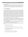
1
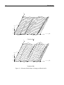
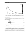
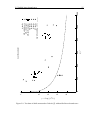
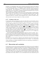
3.5 VEGA - Europe’s small launcher
49
1.5
measured data
1
w̄C , [mm]
0.5
0
-0.5
-1
-1.5
0
20
40
60
80
100
120
140
160
180
200
scan number
Figure 3.13: Measured data of end ring
Also no extra waves appear in the data. If one calculates the magnification of the waves
due to the roller mounting for each wave separately, it is observed that some wave numbers are amplified whereas others are reduced. In Table 3.2 the magnification factors for
the global imperfections are shown for all the larger wave numbers. Notice further the
table starts with m = 2, as the m = 1 term is caused by the offset between the centre
of the shell and the rotation point of the test setup. This offset will be eliminated in the
best-fit step in the next section.
wave number magnification factor
2
-0.88179
3
-1.8257
4
-2.3357
5
-2.1439
6
-1.3510
7
-0.37371
8
0.27454
Table 3.2: Magnification factor of the Fourier coefficients of the end ring imperfections
Applying the scale factors on the Fourier coefficients of the measured data yields the
actual imperfection on the end ring. The results of the calculations are shown in Figure 3.16. The continuous line are the points measured by the LVDT, whereas the dashed
line is the actual imperfection of the end ring. The small waves due to the play of the
setup have been subtracted from the original measured data, and the long waves have