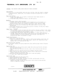
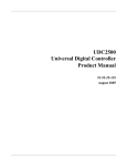
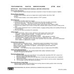
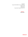
1
EIO0000000107 10/2008
Sherpa Predictive Control
Library V3.0
for Unity Pro and Concept
EIO0000000107.00
10/2008
www.schneider-electric.com
© 2008 Schneider Electric. All rights reserved.
2
EIO0000000107 10/2008
Table of Contents
Safety Information . . . . . . . . . . . . . . . . . . . . . . . . . . . . .
About the Book . . . . . . . . . . . . . . . . . . . . . . . . . . . . . . . .
5
7
Part I General Information . . . . . . . . . . . . . . . . . . . . . . . .
9
Chapter 1 Using the Sherpa Predictive Control Library with
Unity Pro or Concept . . . . . . . . . . . . . . . . . . . . . . . . . . .
11
Using the Sherpa Predictive Control Library with Unity Pro or Concept
Unity Pro: Block Availability on the Various Hardware Platforms . . . . .
Concept: Block Availability on the Various Hardware Platforms . . . . . .
12
13
14
Chapter 2 Predictive Control. . . . . . . . . . . . . . . . . . . . . . . . . . . . . .
15
General Principles of Model Based Predictive Control . . . . . . . . . . . . .
Sherpa Predictive Control Description . . . . . . . . . . . . . . . . . . . . . . . . .
16
19
Part II EFB Descriptions . . . . . . . . . . . . . . . . . . . . . . . . .
21
Chapter 3 PCR_SF1: Simple Predictive Controller for First Order
Process . . . . . . . . . . . . . . . . . . . . . . . . . . . . . . . . . . . . . .
23
Brief Description . . . . . . . . . . . . . . . . . . . . . . . . . . . . . . . . . . . . . . . . . .
Detailed Description . . . . . . . . . . . . . . . . . . . . . . . . . . . . . . . . . . . . . . .
24
28
Chapter 4 PCR_EF1: Enhanced Controller: First Order with
Feed-Forward, Cascade, Split Range, Self
Compensation. . . . . . . . . . . . . . . . . . . . . . . . . . . . . . . . .
29
Brief Description . . . . . . . . . . . . . . . . . . . . . . . . . . . . . . . . . . . . . . . . . .
Detailed Description . . . . . . . . . . . . . . . . . . . . . . . . . . . . . . . . . . . . . . .
30
35
Chapter 5 PCR_IF1: Controller for Integrative First Order
Process . . . . . . . . . . . . . . . . . . . . . . . . . . . . . . . . . . . . . .
37
Brief Description . . . . . . . . . . . . . . . . . . . . . . . . . . . . . . . . . . . . . . . . . .
37
Chapter 6 PCR_EIF1: Enhanced Controller: Integrative First
Order Process with Feed-Forward, Cascade, Ramp
Set Point . . . . . . . . . . . . . . . . . . . . . . . . . . . . . . . . . . . . .
41
Brief Description . . . . . . . . . . . . . . . . . . . . . . . . . . . . . . . . . . . . . . . . . .
Detailed Description . . . . . . . . . . . . . . . . . . . . . . . . . . . . . . . . . . . . . . .
42
46
EIO0000000107 10/2008
3
Chapter 7 PCR_RD1: Ramp and Docking Set Point Controller for
First Order Process . . . . . . . . . . . . . . . . . . . . . . . . . . . .
48
53
Chapter 8 PCR_DC3: Dedicated Controller for Third Order
Process . . . . . . . . . . . . . . . . . . . . . . . . . . . . . . . . . . . . . .
55
Brief Description. . . . . . . . . . . . . . . . . . . . . . . . . . . . . . . . . . . . . . . . . .
55
Chapter 9 PCR_ZTR: Zone Control with Non-Linear Time
Response . . . . . . . . . . . . . . . . . . . . . . . . . . . . . . . . . . . .
59
Brief Description. . . . . . . . . . . . . . . . . . . . . . . . . . . . . . . . . . . . . . . . . .
Detailed Description. . . . . . . . . . . . . . . . . . . . . . . . . . . . . . . . . . . . . . .
60
62
Chapter 10 PCR_FIL: Rate Limiter Filter . . . . . . . . . . . . . . . . . . . . .
65
Brief Description. . . . . . . . . . . . . . . . . . . . . . . . . . . . . . . . . . . . . . . . . .
Detailed Description. . . . . . . . . . . . . . . . . . . . . . . . . . . . . . . . . . . . . . .
66
68
Chapter 11 PCR_RSP: Ramp and Docking Set Point Generator .
71
Brief Description. . . . . . . . . . . . . . . . . . . . . . . . . . . . . . . . . . . . . . . . . .
71
Chapter 12 PCR_FF1: Model for First Order Feed-Forward
Compensation . . . . . . . . . . . . . . . . . . . . . . . . . . . . . . . .
77
Brief Description. . . . . . . . . . . . . . . . . . . . . . . . . . . . . . . . . . . . . . . . . .
Detailed Description. . . . . . . . . . . . . . . . . . . . . . . . . . . . . . . . . . . . . . .
78
81
Chapter 13 PCR_IFF1: Model for Feed-Forward Compensation
Used with Integrative First Order System . . . . . . . . . .
83
Brief Description. . . . . . . . . . . . . . . . . . . . . . . . . . . . . . . . . . . . . . . . . .
Detailed Description. . . . . . . . . . . . . . . . . . . . . . . . . . . . . . . . . . . . . . .
84
87
Chapter 14 PCR_SR1: Supervisor for 2 Controllers in Split Range
Configuration . . . . . . . . . . . . . . . . . . . . . . . . . . . . . . . . .
4
47
Brief Description. . . . . . . . . . . . . . . . . . . . . . . . . . . . . . . . . . . . . . . . . .
Detailed Description. . . . . . . . . . . . . . . . . . . . . . . . . . . . . . . . . . . . . . .
89
Brief Description. . . . . . . . . . . . . . . . . . . . . . . . . . . . . . . . . . . . . . . . . .
Detailed Description. . . . . . . . . . . . . . . . . . . . . . . . . . . . . . . . . . . . . . .
90
92
Chapter 15 PCR_ESR1: Enhanced Split Range Supervisor with
Min Constraints Different from Zero . . . . . . . . . . . . . .
95
Brief Description. . . . . . . . . . . . . . . . . . . . . . . . . . . . . . . . . . . . . . . . . .
Detailed Description. . . . . . . . . . . . . . . . . . . . . . . . . . . . . . . . . . . . . . .
96
100
Index . . . . . . . . . . . . . . . . . . . . . . . . . . . . . . . . . . . . . . . . .
101
EIO0000000107 10/2008
Safety Information
§
Important Information
NOTICE
Read these instructions carefully, and look at the equipment to become familiar with
the device before trying to install, operate, or maintain it. The following special
messages may appear throughout this documentation or on the equipment to warn
of potential hazards or to call attention to information that clarifies or simplifies a
procedure.
EIO0000000107 10/2008
5
PLEASE NOTE
Electrical equipment should be installed, operated, serviced, and maintained only by
qualified personnel. No responsibility is assumed by Schneider Electric for any
consequences arising out of the use of this material.
6
EIO0000000107 10/2008
About the Book
At a Glance
Document Scope
This document describes the function blocks of the Sherpa Predictive Control
library.
This document is valid for the Sherpa Predictive Control library version 3.0.
Validity Note
This documentation applies to Unity Pro 2.3 and later and to Concept 2.5 and later.
The data and illustrations found in this document are not binding. We reserve the
right to modify our products in line with our policy of continuous product
development. The information in this document is subject to change without notice
and should not be construed as a commitment by Schneider Electric.
Related Documents
Title of Documentation
Reference Number
Unity Pro, Program Languages and Structure, Reference Manual
-
Concept User Manual
33002204
You can download these technical publications and other technical information from
our website at www.schneider-electric.com.
Product Related Information
Schneider Electric assumes no responsibility for any errors that may appear in this
document. If you have any suggestions for improvements or amendments or have
found errors in this publication, please notify us.
No part of this document may be reproduced in any form or by any means, electronic
or mechanical, including photocopying, without express written permission of
Schneider Electric.
EIO0000000107 10/2008
7
All pertinent state, regional, and local safety regulations must be observed when
installing and using this product. For reasons of safety and to ensure compliance
with documented system data, only the manufacturer should perform repairs to
components.
When controllers are used for applications with technical safety requirements,
please follow the relevant instructions.
Failure to use Schneider Electric software or approved software with our hardware
products may result in injury, harm, or improper operating results.
Failure to observe this product related warning can result in injury or equipment
damage.
User Comments
We welcome your comments about this document. You can reach us by e-mail at
[email protected].
8
EIO0000000107 10/2008
General Information
EIO0000000107 10/2008
General Information
I
Introduction
This part contains general information about the Sherpa Predictive Control library.
What's in this Part?
This part contains the following chapters:
Chapter
EIO0000000107 10/2008
Chapter Name
Page
1
Using the Sherpa Predictive Control Library with Unity Pro or
Concept
11
2
Predictive Control
15
9
General Information
10
EIO0000000107 10/2008
Using Sherpa Predictive Control Library with Unity Pro or Concept
EIO0000000107 10/2008
Using the Sherpa Predictive
Control Library with Unity Pro or
Concept
1
Introduction
You can use the Sherpa Predictive Control library with Unity Pro or with Concept.
What's in this Chapter?
This chapter contains the following topics:
Topic
EIO0000000107 10/2008
Page
Using the Sherpa Predictive Control Library with Unity Pro or Concept
12
Unity Pro: Block Availability on the Various Hardware Platforms
13
Concept: Block Availability on the Various Hardware Platforms
14
11
Using Sherpa Predictive Control Library with Unity Pro or Concept
Using the Sherpa Predictive Control Library with Unity Pro or Concept
Introduction
You can use the Sherpa Predictive Control library with Unity Pro or with Concept.
Related Documents
For further details on how to use EFBs with Unity Pro or Concept (for example EN
and ENO), please refer to the respective documentation.
z For Unity Pro please refer to Unity Pro, Program Languages and Structure,
Reference Manual.
z For Concept please refer to Concept User Manual.
12
EIO0000000107 10/2008
Using Sherpa Predictive Control Library with Unity Pro or Concept
Unity Pro: Block Availability on the Various Hardware Platforms
Introduction
Block availability by hardware platform can be found in the following table.
Block Availability
Group
Block Name
Block Type
M340
Premium
Quantum
Controller
PCR_SF1
EFB
+
+
+
PCR_EF1
EFB
+
+
+
PCR_IF1
EFB
+
+
+
Generator
Model
Supervisor
PCR_EIF1
EFB
+
+
+
PCR_RD1
EFB
+
+
+
PCR_DC3
EFB
+
+
+
PCR_ZTR
EFB
+
+
+
PCR_FIL
EFB
+
+
+
PCR_RSP
EFB
+
+
+
PCR_FF1
EFB
+
+
+
PCR_IFF1
EFB
+
+
+
PCR_SR1
EFB
+
+
+
PCR_ESR1
EFB
+
+
+
Legend:
EIO0000000107 10/2008
+
yes
-
no
13
Using Sherpa Predictive Control Library with Unity Pro or Concept
Concept: Block Availability on the Various Hardware Platforms
Introduction
Block availability by hardware platform can be found in the following table.
Block Availability
Group
Block Name
Block Type
Atrium
Quantum Momentum
Compact
Controller
PCR_SF1
EFB
+
+
+
+
PCR_EF1
EFB
+
+
+
+
PCR_IF1
EFB
+
+
+
+
PCR_EIF1
EFB
+
+
+
+
PCR_RD1
EFB
+
+
+
+
Generator
Model
Supervisor
PCR_DC3
EFB
+
+
+
+
PCR_ZTR
EFB
+
+
+
+
PCR_FIL
EFB
+
+
+
+
PCR_RSP
EFB
+
+
+
+
PCR_FF1
EFB
+
+
+
+
PCR_IFF1
EFB
+
+
+
+
PCR_SR1
EFB
+
+
+
+
PCR_ESR1
EFB
+
+
+
+
Legend:
14
+
yes
-
no
EIO0000000107 10/2008
Predictive Control
EIO0000000107 10/2008
Predictive Control
2
Introduction
This chapter provides information about the general principles of predictive control
and general information about Sherpa Predictive Control.
What's in this Chapter?
This chapter contains the following topics:
Topic
EIO0000000107 10/2008
Page
General Principles of Model Based Predictive Control
16
Sherpa Predictive Control Description
19
15
Predictive Control
General Principles of Model Based Predictive Control
Introduction
A model based predictive controller is a controller that uses a model in real time for
the computation of the control action to be applied. The main aspects of this
controller are given below.
Model
The model which is embedded in the controller is a mathematical equation that
computes a 'model' output which is comparable to the process output PV (Process
Variable).
The model represents the relationship linking the process input(s) to the process
output.
This model must be identified: the parameters of the model are to be estimated from
recorded plant tests.
The model is used to predict the process output and to compute the control action
in order to satisfy a given target specified on the PV.
16
EIO0000000107 10/2008
Predictive Control
Future Desired Trajectory
At present time (n), the process output is PV(n) and the set point value is SP(n).
The future desired trajectory (so-called reference trajectory) is the desired behavior
of the process output to move from its present value PV(n) to SP(n) in the future.
The reference trajectory is computed by a first order system (see above) and the
response time of this trajectory is the closed loop response time: the PV will respond
to a set point step change with the response time given by the user.
The closed loop response time (TRBF) is a specification which defines the strength
or the smoothness of the controller. There is a trade-off between dynamic
performance and robustness. The controller is more robust when the specified
TRBF is longer.
An intermediate target is selected along that trajectory at a future time(n+H), where
H is called the coincidence point. A simple rule for the coincidence point is to set it
to the third of the 95% response time: H=TRBF/3.
Solver
The solver is the part of the controller which computes the control action to be
applied in such a way the predicted output at time (n+H) is equal to the reference
trajectory at the same future instant.
The computed control action takes into account the constraints which limit the input
moves (high and low limits and rate of change).
EIO0000000107 10/2008
17
Predictive Control
Self Compensation
Some non measured variables may disturb the process.
With unmeasured ramp-type disturbance, a bias between PV (Process Variable)
and SP (Set Point) may appear.
The aim of the self-compensator is to reject this kind of disturbance, and to avoid
such a bias.
18
EIO0000000107 10/2008
Predictive Control
Sherpa Predictive Control Description
Introduction
Sherpa Predictive Control belongs to the Model Based Predictive Control
technology and is dedicated to SISO (Single Input Single Output) processes,
including feed forwarding facilities.
Sherpa Predictive Control Design
Sherpa Predictive Control was initially designed to cope with the control issues met
on chemical reactors (batch or continuous).
Therefore, that led to some physical modelling of the typical architectures of heat
exchanges used on such chemical plants.
The obtained relationships can be represented by non linear first order systems and
model based predictive controllers were designed to cope with these targets.
Several complementary functions were developed as complements to these
controllers to match the specific requirements of reactor temperature control, such
as an efficient SPLIT RANGE module and a smart temperature profile builder linked
with a predictive functional controller, which together perform a close tracking of
such profiles without overshoots.
Since non linear first order controllers were developed, they can be used profitably
on any other kind of SISO process.
EFBs
Each Sherpa Predictive Control EFB (Elementary Function Block) is a program
which is represented as a block with inputs and outputs.
When a control structure is to be integrated, in case of PLCs the blocks can be
graphically linked (according to the IEC 1131-3 norm).
EIO0000000107 10/2008
19
Predictive Control
Groups
Group
EFB
Description
Controller
PCR_SF1
simple predictive controller for first order process
PCR_EF1
enhanced controller for first order process with feed-forward, cascade with MV constraint transfer, split range,
self compensation
PCR_IF1
controller for integrative first order process
PCR_EIF1
enhanced controller for Integrative first order process
with feed-forward, cascade with MV constraint transfer
PCR_RD1
ramp and docking set point controller for first order process
PCR_DC3
dedicated controller for third order process
Generator
Model
Supervisor
20
PCR_ZTR
zone control with non-linear time response
PCR_FIL
rate limiter filter
PCR_RSP
ramp and docking set point generator
PCR_FF1
model for first order feed-forward compensation
PCR_IFF1
model for feed-forward compensation used with integrative first order system
PCR_SR1
supervisor for 2 controllers in split range configuration
PCR_ESR1
enhanced supervisor for 2 controllers in split range configuration with min constraints different from zero
EIO0000000107 10/2008
EFB Descriptions
EIO0000000107 10/2008
EFB Descriptions
II
Introduction
The EFB descriptions are documented according to the EFB groups (see page 20).
What's in this Part?
This part contains the following chapters:
Chapter
EIO0000000107 10/2008
Chapter Name
Page
3
PCR_SF1: Simple Predictive Controller for First Order Process
23
4
PCR_EF1: Enhanced Controller: First Order with Feed-Forward, Cascade, Split Range, Self Compensation
29
5
PCR_IF1: Controller for Integrative First Order Process
37
6
PCR_EIF1: Enhanced Controller: Integrative First Order Process with Feed-Forward, Cascade, Ramp Set Point
41
7
PCR_RD1: Ramp and Docking Set Point Controller for First
Order Process
47
8
PCR_DC3: Dedicated Controller for Third Order Process
55
9
PCR_ZTR: Zone Control with Non-Linear Time Response
59
10
PCR_FIL: Rate Limiter Filter
65
11
PCR_RSP: Ramp and Docking Set Point Generator
71
12
PCR_FF1: Model for First Order Feed-Forward Compensation
77
13
PCR_IFF1: Model for Feed-Forward Compensation Used with
Integrative First Order System
83
14
PCR_SR1: Supervisor for 2 Controllers in Split Range Configuration
89
15
PCR_ESR1: Enhanced Split Range Supervisor with Min Constraints Different from Zero
95
21
EFB Descriptions
22
EIO0000000107 10/2008
PCR_SF1: Simple Predictive Controller for First Order Process
EIO0000000107 10/2008
PCR_SF1: Simple Predictive
Controller for First Order Process
3
Introduction
This chapter describes the PCR_SF1 EFB.
What's in this Chapter?
This chapter contains the following topics:
Topic
EIO0000000107 10/2008
Page
Brief Description
24
Detailed Description
28
23
PCR_SF1: Simple Predictive Controller for First Order Process
Brief Description
Function Description
PCR_SF1 is an EFB for simple control of first order process with pure time delay.
PCR_SF1 algorithm is based on predictive control principles:
An internal model of process is used to predict the future behavior of the system.
The model is composed of 3 parameters (see figure below):
z KM: static gain
z TM: time constant
z DM: pure time delay
z
z
The following constraints on the manipulated variable (Y) can be taken into
account:
z YMIN: minimum value for Y
z YMAX: maximum value for Y
z YRATE maximum variation for Y
Additional parameters EN and ENO can be projected.
EN should be enabled at the control sampling time TS.
24
EIO0000000107 10/2008
PCR_SF1: Simple Predictive Controller for First Order Process
Transfer Function
The continuous transfer function of the internal model is:
Representation
Parameter Description
Inputs
EIO0000000107 10/2008
Parameter
Data Type
Meaning
INIT
BOOL
command for model INITialization if TRUE
PV
REAL
Process Variable
SP
REAL
Set Point value
RCPY
REAL
ReCoPY of applied Y value
IMP
PARA_PCR_IMP
Internal Model Parameters
TUNE
PARA_PCR_TUNE
Predictive control TUNing parameters
LIM
PARA_PCR_LIM
LIMitations on manipulated variable Y
MAN
BOOL
TRUE = MANual mode
YMAN
REAL
MANual manipulated variable
25
PCR_SF1: Simple Predictive Controller for First Order Process
Outputs
Parameter
Data Type
Meaning
Y
REAL
manipulated variable
IMV
REAL
Internal Model Value
process value estimated by model
ERR
DINT
ERRor code
Type Description
PARA_PCR_IMP: Internal Model Parameters
Parameter
Data Type
Meaning
KM
REAL
static gain
TM
TIME
time constant
DM
TIME
pure time delay
PARA_PCR_TUNE: Predictive control TUNing parameters
Parameter
Data Type
Meaning
TS
TIME
sampling time
H
TIME
coincidence point
TRBF
TIME
95% closed-loop response time
PARA_PCR_LIM: LIMitations on manipulated variable Y
Parameter
26
Data Type
Meaning
YMIN
REAL
minimum value for Y
YMAX
REAL
maximum value for Y
YRATE
REAL
maximum variation for Y (in unit per second)
EIO0000000107 10/2008
PCR_SF1: Simple Predictive Controller for First Order Process
Runtime Errors
ERR Bit
Meaning
BIT 0 = 1
TS = 0
Behavior
TS is forced to 1
BIT 1 = 1
ABS(KM) < 1.0 e
BIT 2 = 1
DM < 0
BIT 3 = 1
DM > 127 * TS
DM is forced to 127 * TS
BIT 4 = 1
YRATE < 0
YRATE is forced to 0
-6
KM is forced to +/- 1.0 e-6
DM is forced to 0
BIT 5 = 1
YMAX < YMIN
YMIN <-> YMAX and YRATE is forced to 0
BIT 6 = 1
TRBF < 0
TRBF is forced to 0
BIT 7 = 1
H < TS
H is forced to TS
The runtime error system uses binary type outputs (power of 2). So you can detect
several runtime errors occurring at the same time. The output number is the sum of
all ERR bits.
EIO0000000107 10/2008
27
PCR_SF1: Simple Predictive Controller for First Order Process
Detailed Description
Initialization Mode
The INIT flag is used to initialize the current and past states of the internal model.
It is needed when the controller inputs (PV, actuator ) are not representative of the
process.
For instance: temperature measurement of an empty reactor or opened valve
without real action on the process.
Depending on the type of process on which the controller is applied (continuous or
batch), the initialisation has to be performed once or at the beginning of each
production.
INIT has to be done when the process is stabilized, as follows:
Manual Mode
The manual mode is applied if the input MAN is TRUE.
Then, the output of the control block (Y) takes the value of manual manipulated
variable YMAN.
28
EIO0000000107 10/2008
PCR_EF1: Enhanced Controller: First Order with Feed-Forward, Cascade, Split Range, Self Compensation
EIO0000000107 10/2008
PCR_EF1: Enhanced Controller:
First Order with Feed-Forward,
Cascade, Split Range, Self
Compensation
4
Introduction
This chapter describes the PCR_EF1 EFB.
What's in this Chapter?
This chapter contains the following topics:
Topic
EIO0000000107 10/2008
Page
Brief Description
30
Detailed Description
35
29
PCR_EF1: Enhanced Controller: First Order with Feed-Forward, Cascade, Split Range, Self Compensation
Brief Description
Function Description
PCR_EF1 is an EFB for enhanced control of first order process with pure time delay.
PCR_EF1 algorithm is based on predictive control principles:
An internal model of process is used to predict the future behavior of the system.
The model is composed of 3 parameters:
z KM: static gain
z TM: time constant
z DM: pure time delay
z
z
The following constraints on the manipulated variable (Y) can be taken into
account:
z YMIN: minimum value for Y
z YMAX: maximum value for Y
z YRATE: maximum variation for Y
Additional parameters EN and ENO can be projected.
EN should be enabled at the control sampling time TS.
Additional Functions
Compared to PCR_SF1, PCR_EF1 provides the following additional functions:
z FEED FORWARD COMPENSATION:
to take in account a disturbance variable (issued from a disturbance modelling,
see PCR_FF1, or from an other controller)
z SPLIT RANGE COMPENSATION:
to optimize the association of controllers, see PCR_SR1
z SELF COMPENSATOR:
to reject unmeasured ramp type disturbances
30
EIO0000000107 10/2008
PCR_EF1: Enhanced Controller: First Order with Feed-Forward,
Representation
EIO0000000107 10/2008
31
PCR_EF1: Enhanced Controller: First Order with Feed-Forward, Cascade, Split Range, Self Compensation
Parameter Description
Inputs
Parameter
Data Type
Meaning
INIT
BOOL
command for model INITialization if TRUE
PV
REAL
Process Variable
SP
REAL
Set Point value
RCPY
REAL
ReCoPY of applied Y value
FF
REAL
Feed-Forward compensation
IMP
PARA_PCR_IMP
Internal Model Parameters
TUNE
PARA_PCR_TUNE
predictive control TUNing parameters
LIM
PARA_PCR_LIM
LIMitations on manipulated variable Y
SELF_CMP
PARA_PCR_SC
SELF CoMPensator parameters
SPLR_VAL
BOOL
TRUE = SPLit-Range VALidation
SPLR_IMP
PARA_PCR_IMP
Internal Model Parameters from associated
controller
SPLR_TUNE
PARA_PCR_TUNE
Predictive ContRol TUNing parameters from
associated controller
MAN
BOOL
TRUE = MANual mode
YMAN
REAL
MANual manipulated variable
Data Type
Meaning
Outputs
Parameter
32
Y
REAL
manipulated variable
IMV
REAL
Internal Model Value
process value estimated by model
SP_CSTR
REAL
Set Point transferred to upper level
SPLR_FL
REAL
feed back value for associated controller
ERR
DINT
ERRor code
EIO0000000107 10/2008
PCR_EF1: Enhanced Controller: First Order with Feed-Forward,
Type Description
PARA_PCR_IMP: Internal Model Parameters
Parameter
Data Type
Meaning
KM
REAL
static gain
TM
TIME
time constant
DM
TIME
pure time delay
PARA_PCR_TUNE: Predictive ContRol TUNing parameters
TS
TIME
sampling time
H
TIME
coincidence point
TRBF
TIME
95% closed-loop response time
PARA_PCR_LIM: LIMitations on manipulated variable Y
Parameter
Data Type
Meaning
YMIN
REAL
MINimum value for Y
YMAX
REAL
MAXimum value for Y
YRATE
REAL
Maximum variation for Y (in unit per second)
PARA_PCR_SC: Self Compensator parameters
Parameter
Data Type
Meaning
KSC
REAL
static gain
TSC
TIME
time constant
ERR Bit
Meaning
Behavior
BIT 0 = 1
TS = 0
Runtime Errors
EIO0000000107 10/2008
TS is forced to 1
BIT 1 = 1
ABS(KM) < 1.0 e
BIT 2 = 1
DM < 0
BIT 3 = 1
DM > 127 * TS
DM is forced to 127 * TS
BIT 4 = 1
YRATE < 0
YRATE is forced to 0
-6
KM is forced to +/- 1.0 e-6
DM is forced to 0
BIT 5 = 1
YMAX < YMIN
YMIN <-> YMAX and YRATE is forced to 0
BIT 6 = 1
TRBF < 0
TRBF is forced to 0
BIT 7 = 1
H < TS
H is forced to TS
33
PCR_EF1: Enhanced Controller: First Order with Feed-Forward, Cascade, Split Range, Self Compensation
Invalid setting in Split Range parameters
ERR Bit
Meaning
Behavior
BIT 8 = 1
DM < 0
DM is forced to 0
BIT 9 = 1
DM > 127 * TS
DM is forced to 127 * TS
BIT 10 = 1
TRBF < 0
TRBF is forced to 0
BIT 11 = 1
H < TS
H is forced to TS
Invalid setting in Self Compensator parameters
ERR Bit
Meaning
Behavior
BIT 14 = 1
TSC < 0
TSC is forced to 0
BIT 15 = 1
KSC < 0
KSC is forced to 0
BIT 16 = 1
KSC >KSC_MAX
KSC is forced to KSC_MAX (2.0)
The runtime error system uses binary type outputs (power of 2). So you can detect
several runtime errors occurring at the same time. The output number is the sum of
all ERR bits.
34
EIO0000000107 10/2008
PCR_EF1: Enhanced Controller: First Order with Feed-Forward,
Detailed Description
Cascade Configuration
When an PCR_EF1 controller is used as a SLAVE controller in a cascaded
architecture, it receives a set point from the MASTER controller.
If the output Y, computed by the SLAVE controller, is constrained, the MASTER
Controller must know the value of the set point that can be satisfied by the SLAVE
controller.
That value is computed by the SLAVE controller (SP_CSTR) and sent back to the
master controller.
Example of cascade configuration, using PCR_EF1 blocks
EIO0000000107 10/2008
35
PCR_EF1: Enhanced Controller: First Order with Feed-Forward, Cascade, Split Range, Self Compensation
Tuning of the Self Compensator Parameters
Some non measured variables may disturb the process.
With unmeasured ramp-type disturbance, a bias between PV and SP may appear.
The aim of the self-compensator is to reject this kind of disturbance.
The gain KSC and the time constant TSC are the parameters of the PARA_PCR_SC
structure used with the SELF_CMP input.
For stability sake, usual values are:
0 ≤ KSC ≤ 1(KSC=0 means no self compensation)
z TSC ≥ max(30*TS, 3*TM, TRBF)
z
36
EIO0000000107 10/2008
PCR_IF1: Controller for Integrative First Order Process
EIO0000000107 10/2008
PCR_IF1: Controller for
Integrative First Order Process
5
Brief Description
Function Description
PCR_IF1 is an EFB for control of integrative first order process with pure time delay.
The algorithm is based on predictive control principles:
z An internal model of process is used to predict the future behavior of the
integrative system with delay.
The model is composed of 3 parameters (see figure below):
z KM: static gain
z TM: time constant
z DM: pure time delay
z
z
The integrative part is decomposed. This is tuned by DECOMP input.
For stability sake, it is better to set this input at the maximum value among:
30*TS, 3*TM, TRBF
The following constraints on the manipulated variable (Y) can be taken into
account:
z YMIN: minimum value for Y
z YMAX: maximum value for Y
z YRATE: maximum variation for Y
Additional parameters EN and ENO can be projected.
EN should be enabled at the control sampling time TS.
EIO0000000107 10/2008
37
PCR_IF1: Controller for Integrative First Order Process
Transfer Function
The continuous transfer function of the internal model is:
Note for Initialization
NOTE: When the process variable PV varies as a ramp before switching on the
controller, it is necessary to estimate the slope of this process variable PV in order
to initialize correctly the model. This estimation is performed during the initialization
phase, as long as INIT equals TRUE. The duration of this phase must be long
enough to perform an estimation not biased by the noise. In case of heavy noise,
more than 10 periods may be required.
38
EIO0000000107 10/2008
PCR_IF1: Controller for Integrative First Order Process
Representation
Parameter Description
Inputs
Parameter
Data Type
Meaning
INIT
BOOL
command for model INITialization if TRUE
PV
REAL
Process Variable
SP
REAL
Set Point value
RCPY
REAL
ReCoPY of applied Y value
IMP
PARA_PCR_IMP
Internal Model Parameters
TUNE
PARA_PCR_TUNE
predictive control TUNing parameters
LIM
PARA_PCR_LIM
LIMitations on manipulated variable Y
DECOMP
TIME
DECOMPosition time constant
MAN
BOOL
TRUE = MANual mode
YMAN
REAL
MANual manipulated variable
Outputs
EIO0000000107 10/2008
Parameter
Data Type
Meaning
Y
REAL
manipulated variable
IMV
REAL
Internal Model Value
process value estimated by model
ERR
DINT
ERRor code
39
PCR_IF1: Controller for Integrative First Order Process
Type Description
PARA_PCR_IMP: Internal Model Parameters
Parameter
Data Type
Meaning
KM
REAL
static gain
TM
TIME
time constant
DM
TIME
pure time delay
PARA_PCR_TUNE: Predictive control TUNing parameters
Parameter
Data Type
Meaning
TS
TIME
sampling time
H
TIME
coincidence point
TRBF
TIME
95% closed-loop response time
PARA_PCR_LIM: LIMitations on manipulated variable Y
Parameter
Data Type
Meaning
YMIN
REAL
MINimum value for Y
YMAX
REAL
MAXimum value for Y
YRATE
REAL
maximum variation for Y (in unit per second)
ERR Bit
Meaning
Behavior
BIT 0 = 1
TS = 0
TS is forced to 1
BIT 1 = 1
ABS(KM) < 1.0 e-6
KM is forced to +/- 1.0 e-6
BIT 2 = 1
DM < 0
DM is forced to 0
BIT 3 = 1
DM > 127 * TS
DM is forced to 127 * TS
BIT 4 = 1
YRATE < 0
YRATE is forced to 0
BIT 5 = 1
YMAX < YMIN
YMIN <-> YMAX and YRATE is forced to 0
BIT 6 = 1
TRBF < 0
TRBF is forced to 0
BIT 7 = 1
H < TS
H is forced to TS
BIT 8 = 1
DECOMP < 0
decomposition time constant DECOMP is
forced to 0
Runtime Errors
The runtime error system uses binary type outputs (power of 2). So you can detect
several runtime errors occurring at the same time. The output number is the sum of
all ERR bits.
40
EIO0000000107 10/2008
PCR_EIF1: Enhanced Controller: Integrative First Order Process with Feed-Forward, Cascade, Ramp Set Point
EIO0000000107 10/2008
PCR_EIF1: Enhanced Controller:
Integrative First Order Process
with Feed-Forward, Cascade,
Ramp Set Point
6
Introduction
This chapter describes the PCR_EIF1 EFB.
What's in this Chapter?
This chapter contains the following topics:
Topic
EIO0000000107 10/2008
Page
Brief Description
42
Detailed Description
46
41
PCR_EIF1: Enhanced Controller: Integrative First Order Process with Feed-Forward, Cascade, Ramp Set Point
Brief Description
Function Description
PCR_EIF1 is an EFB for enhanced control of integrative first order process with pure
time delay.
PCR_EIF1 algorithm is based on predictive control principles:
z An internal model of process is used to predict the future behavior of the
integrative system with delay.
The model is composed of 3 parameters:
z KM: static gain
z TM: time constant
z DM: pure time delay
z
z
The integrative part is decomposed. This is tuned by DECOMP input.
For stability sake, it is better to set this input at the maximum value among:
30*TS, 3*TM, TRBF
The following constraints on the manipulated variable (Y) can be taken into
account:
z YMIN: minimum value for Y
z YMAX: maximum value for Y
z YRATE: maximum variation for Y
Additional parameters EN and ENO can be projected.
EN should be enabled at the control sampling time TS.
Additional Functions
Compared to PCR_IF1, PCR_EIF1 provides the following additional functions:
z FEED FORWARD COMPENSATION
to take in account a disturbance variable (issued from a disturbance modelling,
see PCR_IFF1, or from an other controller)
z CONSTRAINTS TRANSFERRING
z follow up of ramp set points
Note for Initialization
NOTE: When the process variable PV varies as a ramp before switching on the
controller, it is necessary to estimate the slope of this process variable PV in order
to initialize correctly the model. This estimation is performed during the initialization
phase, as long as INIT equals TRUE. The duration of this phase must be long
enough to perform an estimation not biased by the noise. In case of heavy noise,
more than 10 periods may be required.
42
EIO0000000107 10/2008
PCR_EIF1: Enhanced Controller: Integrative First Order Process
Representation
Parameter Description
Inputs
EIO0000000107 10/2008
Parameter
Data Type
Meaning
INIT
BOOL
command for model INITialization if TRUE
PV
REAL
Process Variable
SP
REAL
Set Point value
RCPY
REAL
ReCoPY of applied Y value
IFF
PARA_PCR_IFF
Feed-Forward compensation
IMP
PARA_PCR_IMP
Internal Model Parameters
TUNE
PARA_PCR_TUNE
predictive control TUNing parameters
LIM
PARA_PCR_LIM
LIMitations on manipulated variable Y
DECOMP
TIME
DECOMPosition time constant
SP_SL
REAL
SLope (in unit per second) of the future Set
Point
MAN
BOOL
TRUE = MANual mode
YMAN
REAL
MANual manipulated variable
43
PCR_EIF1: Enhanced Controller: Integrative First Order Process with Feed-Forward, Cascade, Ramp Set Point
Outputs
Parameter
Data Type
Meaning
Y
REAL
manipulated variable
IMV
REAL
Internal Model Value
process value estimated by model
SP_CSTR
REAL
Set Point transferred to upper level
ERR
DINT
ERRor code
Type Description
PARA_PCR_IMP: Internal Model Parameters
Parameter
Data Type
Meaning
KM
REAL
static gain
TM
TIME
time constant
DM
TIME
pure time delay
PARA_PCR_TUNE: Predictive control TUNing parameters
Parameter
Data Type
Meaning
TS
TIME
sampling time
H
TIME
coincidence point
TRBF
TIME
95% closed-loop response time
PARA_PCR_IFF: Feed-Forward Compensation
Parameter
Data Type
Meaning
IFF1
REAL
Feed-Forward compensation for process output
estimation
IFF2
REAL
Feed-Forward compensation at the coincidence
point
PARA_PCR_LIM: LIMitations on manipulated variable Y
44
Parameter
Data Type
Meaning
YMIN
REAL
MINimum value for Y
YMAX
REAL
MAXimum value for Y
YRATE
REAL
Maximum variation for Y (in unit per second)
EIO0000000107 10/2008
PCR_EIF1: Enhanced Controller: Integrative First Order Process
Runtime Errors
ERR Bit
Meaning
BIT 0 = 1
TS = 0
Behavior
TS is forced to 1
BIT 1 = 1
ABS(KM) < 1.0 e
BIT 2 = 1
DM < 0
BIT 3 = 1
DM > 127 * TS
DM is forced to 127 * TS
BIT 4 = 1
YRATE < 0
YRATE is forced to 0
-6
KM is forced to +/- 1.0 e-6
DM is forced to 0
BIT 5 = 1
YMAX < YMIN
YMIN <-> YMAX and YRATE is forced to 0
BIT 6 = 1
TRBF < 0
TRBF is forced to 0
BIT 7 = 1
H < TS
H is forced to TS
BIT 8 = 1
DECOMP < 0
decomposition time constant DECOMP is
forced to 0
The runtime error system uses binary type outputs (power of 2). So you can detect
several runtime errors occurring at the same time. The output number is the sum of
all ERR bits.
EIO0000000107 10/2008
45
PCR_EIF1: Enhanced Controller: Integrative First Order Process with Feed-Forward, Cascade, Ramp Set Point
Detailed Description
Ramp Set Point
Configuration of PCR_EIF1 in case of ramp set point
46
EIO0000000107 10/2008
PCR_RD1: Ramp and Docking Set Point Controller for First Order Process
EIO0000000107 10/2008
PCR_RD1: Ramp and Docking Set
Point Controller for First Order
Process
7
Introduction
This chapter describes the PCR_RD1 EFB.
What's in this Chapter?
This chapter contains the following topics:
Topic
EIO0000000107 10/2008
Page
Brief Description
48
Detailed Description
53
47
PCR_RD1: Ramp and Docking Set Point Controller for First Order Process
Brief Description
Function Description
PCR_RD1 is an EFB for ramp and docking set point control of first order process with
pure time delay.
It has to be used with PCR_RSP block which provides docking set points.
PCR_RD1 algorithm is based on predictive control principles:
An internal model of process is used to predict the future behavior of the system.
For first order system with delay, the model is composed of 3 parameters:
z KM: static gain
z TM: time constant
z DM: pure time delay
z
z
The following constraints on the manipulated variable (Y) can be taken into
account:
z YMIN: minimum value for Y
z YMAX: maximum value for Y
z YRATE: maximum variation for Y
Additional parameters EN and ENO can be projected.
EN should be enabled at the control sampling time TS.
NOTE: This block cannot be used in split-range configuration.
Additional Function
Compared to PCR_EF1, the block PCR_RD1 provides the following additional
function:
Follow-up of ramping set points.
48
EIO0000000107 10/2008
PCR_RD1: Ramp and Docking Set Point Controller for First Order
Representation
EIO0000000107 10/2008
49
PCR_RD1: Ramp and Docking Set Point Controller for First Order Process
Parameter Description
Inputs
Parameter
Data Type
Meaning
INIT
BOOL
Command for model INITialization if True
PV
REAL
Process Variable
SP
REAL
Set Point value
RCPY
REAL
ReCoPY of applied Y value
IMP
PARA_PCR_IMP
Internal Model Parameters
TUNE_RD1
PARA_PCR_ TUNE_RD1
Predictive control TUNing parameters
LIM
PARA_PCR_LIM
LIMitations on manipulated variable Y
SP_PRED
PARA_SP_PRED
PREDicted Set Points values
SELF_CMP
PARA_PCR_SC
SELF CoMPensator parameters
FF1
REAL
Feed-Forward compensation at coincidence point H1
FF2
REAL
Feed-Forward compensation at coincidence point H2
HOLD
BOOL
If TRUE, the predicted set points are hold
to the current set point value.
MAN
BOOL
TRUE = MANual mode
YMAN
REAL
Manual MANipulated Variable
Parameter
Data Type
Meaning
Y
REAL
manipulated variable
IMV
REAL
Internal Model Value
process value estimated by model
Y_RAMP
REAL
RAMP part of the manipulated variable
ERR
DINT
ERRor code
Outputs
50
EIO0000000107 10/2008
PCR_RD1: Ramp and Docking Set Point Controller for First Order
Type Description
PARA_PCR_IMP: Internal Model Parameters
Parameter
Data Type
Meaning
KM
REAL
static gain
TM
TIME
time constant
DM
TIME
pure time delay
PARA_PCR_TUNE_RD1: Predictive control TUNing parameters
Parameter
Data Type
Meaning
TS
TIME
sampling time
H1
TIME
1st coincidence point
H2
TIME
2nd coincidence point
TRBF
TIME
95% closed-loop response time
PARA_PCR_LIM: LIMitations on manipulated variable Y
Parameter
Data Type
Meaning
YMIN
REAL
MINimum value for Y
YMAX
REAL
MAXimum value for Y
YRATE
REAL
maximum variation for Y (in unit per second)
PARA_PCR_PRED: PREDicted set points values
Parameter
Data Type
Meaning
SPH1
REAL
Set Point at current time + H1
SPH2
REAL
Set Point at current time + H2
PARA_PCR_SC: Self Compensator parameters
EIO0000000107 10/2008
Parameter
Data Type
Meaning
KSC
REAL
static gain
TSC
TIME
time constant
51
PCR_RD1: Ramp and Docking Set Point Controller for First Order Process
Runtime Errors
ERR Bit
Meaning
Behavior
BIT 0 = 1
TS = 0
EFB stays in initialization mode (INIT forced to
TRUE)
BIT 1 = 1
ABS(KM) < 1.0 e-6
KM is forced to +/- 1.0 e-6
BIT 2 = 1
DM > 127 * TS
DM is forced to 127 * TS
BIT 3 = 1
YRATE < 0
YRATE is forced to 0
BIT 4 = 1
YMAX < YMIN
YMIN <-> YMAX and YRATE is forced to 0
BIT 5 = 1
H1 < TS
H1 is forced to TS
BIT 6 = 1
H2 < TS
H2 is forced to TS
BIT 7 = 1
H2 <= H1
H2 is forced to H1 + TS
BIT 8 = 1
KSC < 0
KSC is forced to 0
BIT 9 = 1
KSC >KSC_MAX
KSC is forced to KSC_MAX (2.0)
The runtime error system uses binary type outputs (power of 2). So you can detect
several runtime errors occurring at the same time. The output number is the sum of
all ERR bits.
52
EIO0000000107 10/2008
PCR_RD1: Ramp and Docking Set Point Controller for First Order
Detailed Description
PCR_RSP and PCR_RD1 Configuration
This configuration involves 2 blocks:
z PCR_RSP generates predicted set points from a recipe table
z PCR_RD1 computes the action Y from the computed predicted set points.
PCR_RSP and PCR_RD1 configuration
NOTE: When the EFB PCR_RD1 is associated with a PCR_RSP EFB, the sampling
period TS must be a multiple of 1 second and cannot be decimal.
EIO0000000107 10/2008
53
PCR_RD1: Ramp and Docking Set Point Controller for First Order Process
54
EIO0000000107 10/2008
PCR_DC3: Dedicated Controller for Third Order Process
EIO0000000107 10/2008
PCR_DC3: Dedicated Controller
for Third Order Process
8
Brief Description
Function Description
PCR_DC3 is an enhanced controller for 3rd order process with pure time delay.
The algorithm is based on predictive control principles:
An internal model of process is used to predict the future behavior of the system.
The model is composed of 5 parameters:
z KM: static gain
z TM1, TM2, TM3: time constants -> α i = exp(-TS/TMi)
(with TS = sampling time)
z Dm: pure time delay -> r m = DM/TS
z
z
The following constraints on the manipulated variable (Y) can be taken into
account:
z YMIN: minimum value for Y
z YMAX: maximum value for Y
z YRATE: maximum variation for Y
Additional parameters EN and ENO can be projected.
EN should be enabled at the control sampling time TS.
EIO0000000107 10/2008
55
PCR_DC3: Dedicated Controller for Third Order Process
Model
PCR_DC3 is working according to the following discrete model:
Representation
56
EIO0000000107 10/2008
PCR_DC3: Dedicated Controller for Third Order Process
Parameter Description
Inputs
Parameter
Data Type
Meaning
INIT
BOOL
command for model INITialization if TRUE
PV
REAL
Process Variable
SP
REAL
Set Point value
RCPY
REAL
ReCoPY of applied Y value
FF
REAL
Feed-Forward compensation
IMP
PARA_PCR_IMP_DC3
Internal Model Parameters
TUNE
PARA_PCR_TUNE
Predictive Control TUNing parameters
LIM
PARA_PCR_LIM
LIMitations on manipulated variable Y
MAN
BOOL
TRUE = MANual mode
YMAN
REAL
MANual manipulated variable
Outputs
Parameter
Data Type
Meaning
Y
REAL
manipulated variable
IMV
REAL
Internal Model Value
process value estimated by model
SP_CSTR
REAL
Set Point transferred to upper level
ERR
DINT
ERRor code
Type Description
PARA_PCR_IMP_DC3: Internal Model Parameters
EIO0000000107 10/2008
Parameter
Data Type
Meaning
KM
REAL
static gain
TM1
TIME
1st time constant
TM2
TIME
2nd time constant
TM3
TIME
3rd time constant
DM
TIME
pure time delay
57
PCR_DC3: Dedicated Controller for Third Order Process
PARA_PCR_TUNE: Predictive control TUNing parameters
Parameter
Data Type
Meaning
TS
TIME
sampling time
H
TIME
coincidence point
TRBF
TIME
95% closed-loop response time
PARA_PCR_LIM: LIMitations on manipulated variable Y
Parameter
Data Type
Meaning
YMIN
REAL
MINimum value for Y
YMAX
REAL
MAXimum value for Y
YRATE
REAL
maximum variation for Y (in unit per second)
Runtime Errors
ERR Bit
Meaning
Behavior
BIT 0 = 1
TS = 0
TS is forced to 1
BIT 1 = 1
ABS(KM) < 1.0 e-6
KM is forced to +/- 1.0 e-6
BIT 2 = 1
DM < 0
DM is forced to 0
BIT 3 = 1
DM > 127 * TS
DM is forced to 127 * TS
BIT 4 = 1
YRATE < 0
YRATE is forced to 0
BIT 5 = 1
YMAX < YMIN
YMIN <-> YMAX and YRATE is
forced to 0
BIT 6 = 1
TRBF < 0
TRBF is forced to 0
BIT 7 = 1
H < TS
H is forced to TS
The runtime error system uses binary type outputs (power of 2). So you can detect
several runtime errors occurring at the same time. The output number is the sum of
all ERR bits.
58
EIO0000000107 10/2008
PCR_ZTR: Zone Control with Non-Linear Time Response
EIO0000000107 10/2008
PCR_ZTR: Zone Control with NonLinear Time Response
9
Introduction
This chapter describes the PCR_ZTR EFB.
What's in this Chapter?
This chapter contains the following topics:
Topic
EIO0000000107 10/2008
Page
Brief Description
60
Detailed Description
62
59
PCR_ZTR: Zone Control with Non-Linear Time Response
Brief Description
Function Description
PCR_ZTR is an EFB for changing automatically the closed-loop time-response
(TRBF) when the process variable (PV) is inside or outside a zone.
PCR_ZTR algorithm is based on basic principle:
When the PV is outside the zone, TRBF is set to TRBF_LO.
The Controller will put the PV back inside the zone.
z When the PV is inside the zone, TRBF varies linearly between TRBF_LO and
TRBF_HI as a function of the (PV-SP) deviation.
z
Evolution of TRBF
Additional parameters EN and ENO can be projected.
EN should be enabled at the control sampling time TS.
60
EIO0000000107 10/2008
PCR_ZTR: Zone Control with Non-Linear Time Response
Representation
Parameter Description
Inputs
Parameter
Data Type
Meaning
PV
REAL
Process Variable
SP
REAL
Set Point value
TUNE_ZTR
PARA_ZTR
ZTR Parameters
Data Type
Meaning
Outputs
Parameter
TRBF
TIME
95% closed-loop response time
ERR
DINT
ERRor code
Type Description
PARA_ZTR: ZTR Parameters
Parameter
Data Type
Meaning
ZONE
REAL
ZONE value
TRBF_LO
TIME
TRBF LOw value
TRBF_HI
TIME
TRBF HIgh value
Runtime Errors
ERR Bit
Meaning
Behavior
BIT 0 = 1
TRBF_HI<TRBF_LO
TRBF_HI is set to TRBF_LO
BIT 1 = 1
ZONE < 0
ZONE is set to 0
The runtime error system uses binary type outputs (power of 2). So you can detect
several runtime errors occurring at the same time. The output number is the sum of
all ERR bits.
EIO0000000107 10/2008
61
PCR_ZTR: Zone Control with Non-Linear Time Response
Detailed Description
Principles
The zone control is a way to obtain a smoother controller when the PV is rather close
to its set point in order to avoid active control actions produced by noisy
measurements.
The controller is thus less active than when the PV is far from the set point. This
technique is not equivalent to a dead zone which does not act as long as the PV is
within the dead zone.
The zone control does not leave any constant deviation. It will make the PV move
back slowly to the set point value.
z When PV is outside the zone, the TRBF is set to TRBF_LO (fastest response).
z When PV is inside the zone, TRBF is computed as follows:
z TRBF = TRBF_HI - (TRBF_HI - TRBF_LO) x |EPS| / ZONE
z with: EPS = SP - PV
This continuous variation of TRBF with EPS avoids bumps when crossing the zone
borders and makes the controller strength proportional to the deviation.
The output TRBF is to be one of the parameters of the PARA_PCR_TUNE of a
controller block.
62
EIO0000000107 10/2008
PCR_ZTR: Zone Control with Non-Linear Time Response
Usage
Use of zone control with an PCR_EF1 block
EIO0000000107 10/2008
63
PCR_ZTR: Zone Control with Non-Linear Time Response
64
EIO0000000107 10/2008
PCR_FIL: Rate Limiter Filter
EIO0000000107 10/2008
PCR_FIL: Rate Limiter Filter
10
Introduction
This chapter describes the PCR_FIL EFB.
What's in this Chapter?
This chapter contains the following topics:
Topic
EIO0000000107 10/2008
Page
Brief Description
66
Detailed Description
68
65
PCR_FIL: Rate Limiter Filter
Brief Description
Function Description
The PCR_FIL block limits the first derivative of a signal passing through it.
The input is supposed to be generated at a sampling period TS1 which is a multiple
of the period TS0 of a block using it downward.
For instance, TS1 is the period of a master controller and TS0 the period of a slave
controller.
The output signal joins the new input by (TS1/TS0) small steps.
Additional parameters EN and ENO can be projected.
EN should be enabled at the control sampling time TS.
66
EIO0000000107 10/2008
PCR_FIL: Rate Limiter Filter
Representation
Parameter Description
Inputs
Parameter
Data Type
Meaning
INIT
BOOL
Command for INITialization if TRUE
TS1
TIME
sampling period of the block generating the IN
signal
TS0
TIME
sampling period of the block using the OUT signal
IN
REAL
signal to be filtered
Data Type
Meaning
OUT
REAL
filtered signal
ERR
DINT
ERRor code
ERR Bit
Meaning
Behavior
BIT 0 = 1
TS1 < TS0
TS1 is forced to TS0, so OUT=IN
BIT 1 = 1
(TS1 / TS0) > 128
The OUT joins the new IN in 128 sampling TS0.
Outputs
Parameter
Runtime Errors
The runtime error system uses binary type outputs (power of 2). So you can detect
several runtime errors occurring at the same time. The output number is the sum of
all ERR bits.
EIO0000000107 10/2008
67
PCR_FIL: Rate Limiter Filter
Detailed Description
Principles
The output is generated by a meaning filter working at period TS0, according to the
equation below:
See below an example with a ratio R between the periods equal to 6:
PCR_FIL with: TS1 = 3 s and TS0 = 0.5 s
68
EIO0000000107 10/2008
PCR_FIL: Rate Limiter Filter
Usage
Use of PCR_FIL
EIO0000000107 10/2008
69
PCR_FIL: Rate Limiter Filter
70
EIO0000000107 10/2008
PCR_RSP: Ramp and Docking Set Point Generator
EIO0000000107 10/2008
PCR_RSP: Ramp and Docking Set
Point Generator
11
Brief Description
Function Description
PCR_RSP is an EFB to compute ramp and docking set points necessary for
PCR_RD1 EFB (see page 53), from a recipe table.
A recipe table is a set point profile composed of several breaking points (up to 15).
Each of them is defined by 3 values (T: time, V: value, D: docking horizon).
The docking horizon represents the length of the rounded target before and after the
breaking point.
PCR_RSP algorithm provides 4 set points each time:
z SP: docking set point at current time
z SP_PRED: structure which contains 2 predictive docking set points
z SPH1: future set point at H1 time
z SH2: future set point at H2 time
z
EIO0000000107 10/2008
SPRAMP: set point at current time without docking
71
PCR_RSP: Ramp and Docking Set Point Generator
The algorithm is designed for real time use:
z the profile specifications may be modified in real time during the progress of the
profile but such modifications are to be avoided during the docking phases
z capability to switch to standby mode in order to manipulate the controller set point
manually
z bumping minimization on the docked set points in case the target is modified by
the user
z delivery of complementary information:
z remaining time before the next docking
z flag FL_DOCK set to TRUE when the present time is a 'sensitive' period (if the
local target is modified now, the computed set points may bump)
z flag END set to TRUE when at the end of the recipe
Additional parameters EN and ENO can be projected.
EN should be enabled at the control sampling time TS.
NOTE: For this EFB, the sampling period TS must be a multiple of 1 second and
cannot be decimal.
Representation
72
EIO0000000107 10/2008
PCR_RSP: Ramp and Docking Set Point Generator
Parameter Description
Inputs
Parameter
Data Type
Meaning
START
BOOL
block activation
RECIPE
PARA_PCR_REC
profile defined by the recipe
IMP
PARA_PCR_IMP
Internal Model Parameters of associated
PCR_RD1 block
TUNE_RD1
PARA_PCR_ TUNE_RD1
TUNing parameters of the PCR_RD1 controller
HOLD
BOOL
block status
FALSE -> active, TRUE -> standby
Parameter
Data Type
Meaning
SP
REAL
Set Point value
Outputs
EIO0000000107 10/2008
SP_PRED
PARA_SP_PRED
PREDicted Set Point values
SPRAMP
REAL
raw Set Point value
FL_DOCK
BOOL
Flag: set to TRUE when the docked set point
values are being computed.
Changing the target when FL_DOCK=TRUE
may cause bumps on the set point.
TIMELEFT
TIME
remaining time before the next docking
END
BOOL
TRUE = the profile is completed
ERR
DINT
ERRor code
ERR_REC
DINT
ERRor code on the profile
73
PCR_RSP: Ramp and Docking Set Point Generator
Type Description
PARA_PCR_REC: profile to be fulfilled
Parameter
Data Type
Meaning
NPOINT
INT
Number of POINTs
TABPT
ARRAY[15] of
PARA_RECIPE
profile
PARA_RECIPE: point defining the profile
Parameter
Data Type
Meaning
T
TIME
Time to reach the point
V
REAL
Value of the point
D
TIME
Docking horizon
PARA_PCR_IMP: Internal Model Parameters
Parameter
Data Type
Meaning
KM
REAL
static gain
TM
TIME
time constant
DM
TIME
pure time delay
PARA_PCR_TUNE_RD1: Predictive control TUNing parameters
Parameter
Data Type
Meaning
TS
TIME
sampling time
H1
TIME
1st coincidence point
H2
TIME
2nd coincidence point
TRBF
TIME
95% closed-loop response time
PARA_PCR_PRED: PREDicted set points values
74
Parameter
Data Type
Meaning
SPH1
REAL
Set Point at current time + H1
SPH2
REAL
Set Point at current time + H2
EIO0000000107 10/2008
PCR_RSP: Ramp and Docking Set Point Generator
Runtime Errors
Invalid setting on the block
ERR Bit
Meaning
Behavior
BIT 0 = 1
TS = 0
block in stop mode (START is set to
FALSE)
BIT 1 = 1
H1 < TS
H1 is forced to TS
BIT 2 = 1
H2 < TS
H2 is forced to TS
BIT 3 = 1
H2 <= H1
H2 is forced to H1 + TS
Invalid setting on the profile
ERR_REC Bit
Meaning
Behavior
BIT 0 = 1
RECIPE.NPOINT > 15
RECIPE.NPOINT set to 15
BIT 1 = 1
TABPT[0].T < Ts
TABPT[0].T set to Ts
BIT 2 = 1
TABPT[0].D>(TABPT[0].T/2)
TABPT[0].D set to(TABPT[0].T/2)
...
...
...
BIT 2*NPOINT-1 TABPT[NPOINT-1].T < Ts
=1
TABPT[NPOINT-1].T set to Ts
BIT 2*NPOINT = TABPT[NPOINT-1].D
1
>(TABPT[NPOINT-1].T/2
TABPT[NPOINT-1].D set to
(TABPT[NPOINT-1].T/2)
The runtime error system uses binary type outputs (power of 2). So you can detect
several runtime errors occurring at the same time. The output number is the sum of
all ERR bits.
EIO0000000107 10/2008
75
PCR_RSP: Ramp and Docking Set Point Generator
76
EIO0000000107 10/2008
PCR_FF1: Model for First Order Feed-Forward Compensation
EIO0000000107 10/2008
PCR_FF1: Model for First Order
Feed-Forward Compensation
12
Introduction
This chapter describes the PCR_FF1 EFB.
What's in this Chapter?
This chapter contains the following topics:
Topic
EIO0000000107 10/2008
Page
Brief Description
78
Detailed Description
81
77
PCR_FF1: Model for First Order Feed-Forward Compensation
Brief Description
Function Description
PCR_FF1 computes a compensation value to be applied to the controller in order to
compensate a first order disturbance:
z As input, this block receives:
z the parameters of the disturbance model
z the controller model and tuning parameters
z
As output, this block computes the feed forward compensation to be applied to
the controller.
Additional parameters EN and ENO can be projected.
EN should be enabled at the control sampling time TS.
78
EIO0000000107 10/2008
PCR_FF1: Model for First Order Feed-Forward Compensation
Representation
Parameter Description
Inputs
Parameter
Data Type
Meaning
INIT
BOOL
command for model INITialization if TRUE
VALID
BOOL
VALIDation of disturbance compensation if
TRUE
PV
REAL
Process Variable (measured disturbance)
IMP
PARA_PCR_IMP
Internal Model Parameters for disturbance
CTRL_IMP
PARA_PCR_IMP
Internal Model Parameters of ConTRoLler
CTRL_TUNE
PARA_PCR_TUNE
TUNing Parameters of ConTRoLler
Data Type
Meaning
Outputs
Parameter
EIO0000000107 10/2008
FF
REAL
Feed-Forward compensation
IMV
REAL
Internal Model Value
disturbance value estimated by model
ERR
DINT
ERRor code
79
PCR_FF1: Model for First Order Feed-Forward Compensation
Type Description
PARA_PCR_IMP: Internal Model Parameters
Parameter
Data Type
Meaning
KM
REAL
static gain
TM
TIME
time constant
DM
TIME
pure time delay
PARA_PCR_TUNE: Predictive control TUNing parameters
Parameter
Data Type
Meaning
TS
TIME
sampling time
H
TIME
coincidence point
TRBF
TIME
95% closed-loop response time
ERR Bit
Meaning
Behavior
BIT 0 = 1
TS = 0
TS is forced to 1
BIT 2 = 1
disturbance DM < 0
disturbance DM is forced to 0
BIT 3 = 1
disturbance DM >127 * TS disturbance DM is forced to 127 * TS
BIT 4 = 1
DM < 0
Runtime Errors
DM is forced to 0
BIT 5 = 1
DM > 127 * TS
DM is forced to 127 * TS
BIT 6 = 1
TRBF < 0
TRBF is forced to 0
BIT 7 = 1
H < TS
H is forced to TS
The runtime error system uses binary type outputs (power of 2). So you can detect
several runtime errors occurring at the same time. The output number is the sum of
all ERR bits.
80
EIO0000000107 10/2008
PCR_FF1: Model for First Order Feed-Forward Compensation
Detailed Description
Usage
The block is used as shown below:
z PCR_FF1 computes the effect of the disturbance DIST_PV on the process output
PV
z PCR_EF1 computes the action Y, taking account the disturbance effect.
Example of feed-forward configuration, using PCR_FF1 and PCR_EF1 blocks
EIO0000000107 10/2008
81
PCR_FF1: Model for First Order Feed-Forward Compensation
82
EIO0000000107 10/2008
PCR_IFF1: Model for Feed-Forward Compensation Used with Integrative First Order System
EIO0000000107 10/2008
PCR_IFF1: Model for FeedForward Compensation Used with
Integrative First Order System
13
Introduction
This chapter describes the PCR_IFF1 EFB.
What's in this Chapter?
This chapter contains the following topics:
Topic
EIO0000000107 10/2008
Page
Brief Description
84
Detailed Description
87
83
PCR_IFF1: Model for Feed-Forward Compensation Used with Integrative First Order System
Brief Description
Function Description
PCR_IFF1 computes a compensation value to be applied to the controller of an
integrative first order process, in order to compensate a first order disturbance
integrative or not.
z As input, this block receives:
z the parameters of the disturbance model
z the controller model and tuning parameters
z
As output, this block computes the feed forward compensation to apply to the
controller.
Additional parameters EN and ENO can be projected.
EN should be enabled at the control sampling time TS.
84
EIO0000000107 10/2008
PCR_IFF1: Model for Feed-Forward Compensation Used with Inte-
Representation
Parameter Description
Inputs
Parameter
Data Type
Meaning
INIT
BOOL
command for model INITialization if TRUE
VALID
BOOL
VALIDation of disturbance compensation if
TRUE
PV
REAL
Process Variable (measured disturbance)
IMP
PARA_PCR_IMP
Internal Model Parameters for disturbance
INTEGR
BOOL
TRUE = the disturbance model is INTEGRative
CTRL_IMP
PARA_PCR_IMP
Internal Model Parameters of ConTRoLler
CTRL_TUNE
PARA_PCR_TUNE
TUNing Parameters of controller
DECOMP
TIME
DECOMPosition time constant
Outputs
EIO0000000107 10/2008
Parameter
Data Type
Meaning
IFF
PARA_PCR_IFF
Feed-Forward compensation
IMV
REAL
Internal Model Value
disturbance value estimated by model
ERR
DINT
ERRor code
85
PCR_IFF1: Model for Feed-Forward Compensation Used with Integrative First Order System
Type Description
PARA_PCR_IMP: Internal Model Parameters
Parameter
Data Type
Meaning
KM
REAL
static gain
TM
TIME
time constant
DM
TIME
pure time delay
PARA_PCR_TUNE: Predictive control TUNing parameters
Parameter
Data Type
Meaning
TS
TIME
sampling time
H
TIME
coincidence point
TRBF
TIME
95% closed-loop response time
PARA_PCR_IFF: Feed-Forward Compensation
Parameter
Data Type
Meaning
IFF1
REAL
Feed-Forward compensation for process output
estimation
IFF2
REAL
Feed-Forward compensation at the coincidence
point
ERR Bit
Meaning
Behavior
BIT 0 = 1
TS = 0
TS is forced to 1
BIT 2 = 1
disturbance DM < 0
disturbance DM is forced to 0
BIT 3 = 1
disturbance DM >127*TS
disturbance DM is forced to 127 * TS
BIT 4 = 1
DM < 0
DM is forced to 0
BIT 5 = 1
DM > 127 * TS
DM is forced to 127 * TS
BIT 6 = 1
TRBF < 0
TRBF is forced to 0
BIT 7 = 1
H < TS
H is forced to TS
Runtime Errors
The runtime error system uses binary type outputs (power of 2). So you can detect
several runtime errors occurring at the same time. The output number is the sum of
all ERR bits.
86
EIO0000000107 10/2008
PCR_IFF1: Model for Feed-Forward Compensation Used with Inte-
Detailed Description
Usage
The block is used as shown below:
z PCR_IFF1 computes the effect of the disturbance DIST_PV on the process
output PV
z PCR_EIF1 computes the action Y, taking account the disturbance effect.
Example of feed-forward configuration, using PCR_IFF1 and PCR_EIF1 blocks
EIO0000000107 10/2008
87
PCR_IFF1: Model for Feed-Forward Compensation Used with Integrative First Order System
88
EIO0000000107 10/2008
PCR_SR1: Supervisor for 2 Controllers in Split Range Configuration
EIO0000000107 10/2008
PCR_SR1: Supervisor for 2
Controllers in Split Range
Configuration
14
Introduction
This chapter describes the PCR_SR1 EFB.
What's in this Chapter?
This chapter contains the following topics:
Topic
EIO0000000107 10/2008
Page
Brief Description
90
Detailed Description
92
89
PCR_SR1: Supervisor for 2 Controllers in Split Range Configuration
Brief Description
Function Description
Here the target system has 2 manipulated variables and 1 controlled output.
The 2 actuators (for instance cooling and heating) can be manipulated separately
for controlling the same process output (for instance temperature).
The PCR solution uses 2 separate PCR_EF1 controllers, each of them being
dedicated to the specific dynamic of its own manipulated variable.
The complementary block PCR_SR1 selects which of the 2 calculated MVs is to be
applied.
PCR_SR1 receives the actions calculated by the 2 controllers and informs both
controllers of final decided action.
Additional parameters EN and ENO can be projected.
EN should be enabled at the control sampling time TS.
90
EIO0000000107 10/2008
PCR_SR1: Supervisor for 2 Controllers in Split Range Configura-
Representation
Parameter Description
Inputs
Parameter
Data Type
Meaning
Y1_IN
REAL
manipulated variable Y from controller 1
SP_CSTR1
REAL
SP_CSTR from controller 1
SPLR_FL1
REAL
feed back value from controller 1
Y2_IN
REAL
manipulated variable Y from controller 2
SP_CSTR2
REAL
SP_CSTR from controller 2
SPLR_FL2
REAL
feed back value from controller 2
Outputs
EIO0000000107 10/2008
Parameter
Data Type
Meaning
Y1
REAL
manipulated variable Y for actuator 1
FF1
REAL
feed-forward value toward controller 1
Y2
REAL
manipulated variable Y for actuator 2
FF2
REAL
feed-forward value toward controller 2
SP_CSTR
REAL
Set Point transferred to upper level
91
PCR_SR1: Supervisor for 2 Controllers in Split Range Configuration
Detailed Description
Usage
An example of the structure is represented below.
The configuration involves 3 blocks:
2 PCR_EF1 compute the action Y on each subsystem (cooling and heating for
instance)
z PCR_SR1 chooses the final decision from past actions and from both controller
demands
z
Configuration of PCR_EF1 in split-range control systems
92
EIO0000000107 10/2008
PCR_SR1: Supervisor for 2 Controllers in Split Range Configura-
EIO0000000107 10/2008
93
PCR_SR1: Supervisor for 2 Controllers in Split Range Configuration
Principles
The target is to control the PV by 1 of the 2 actuators (for instance heating or
cooling).
As the model explaining the PV is usually different for each action, a specific
controller is used to compute separately each of the 2 actions (the cooling action and
the heating one).
Since only 1 actuator can be active at a time (the inactive one is equal to 0), the
supervisor has to decide which action (heating or cooling) must be applied.
When 1 action is equal to 0.0, the action to be applied is the positive action.
The critical cases are when both actions are positive. In that case the action
computed by the last active controller is applied.
A flag is used to remember which controller is working (heating or cooling).
Detailed Logic
The logic is detailed in the following table.
Split range logic with minimum constraints equal to 0.0
-
Status of Calculated MV
Flag Active
Decision of Supervisor
Case
Y1_IN
Y2_IN
0 -> controller 1
1 -> controller 2
Y1
1
+
0.0
0/1
Y1_IN
0.0
SP_CSTR1
0
2
0.0
+
1/0
0.0
Y2_IN
SP_CSTR2
1
3
0.0
0.0
0
0.0
0.0
SP_CSTR1
0
4
0.0
0.0
1
0.0
0.0
SP_CSTR2
1
5
+
+
0
Y1_IN
0.0
SP_CSTR1
0
6
+
+
1
0.0
Y2_IN
SP_CSTR2
1
Y2
SP_CSTR
Flag
The 2 feed-forward outputs are given by:
FF1 = SPLR_FL2
FF2 = SPLR_FL1
z
94
EIO0000000107 10/2008
PCR_ESR1: Enhanced Split Range Supervisor with Min Constraints Different from Zero
EIO0000000107 10/2008
PCR_ESR1: Enhanced Split
Range Supervisor with Min
Constraints Different from Zero
15
Introduction
This chapter describes the PCR_ESR1 EFB.
What's in this Chapter?
This chapter contains the following topics:
Topic
Brief Description
Detailed Description
EIO0000000107 10/2008
Page
96
100
95
PCR_ESR1: Enhanced Split Range Supervisor with Min Constraints Different from Zero
Brief Description
Function Description
In most cases the min constraints of the actuators are 0%, but one can meet
applications for which these constraints are different from zero.
In the version of the PCR split range described in the previous section (see page
89), the logical block PCR_SR1 assumes that both min constraints are zero.
Then the control block (for example "hot controller") currently computing the action
to be applied, considers that the other action (for example "cold valve") is closed.
The prediction based on that assumption (for example cold valve position = 0 and
hot valve position being computed) gets wrong if the min constraint of the "nonactive" controller (for example "cold controller") is not zero.
In order to take the non-zero min constraints into account, the PCR_ESR1 split-range
block is created, having 2 complementary inputs (the limitations LIM1 and LIM2 on
the manipulated variables of both controllers), since the logical rule is now based on
min constraints that are different from zero.
Additional parameters EN and ENO can be projected.
EN should be enabled at the control sampling time TS.
Note for Time-Varying Min Constraints
This version works correctly if the min constraints are different from zero, but as long
as these min constraints are kept constant.
If the min constraint values were to be modified in real time, then one should pay
attention for the following reason:
The blocks architecture is such that any min constraint value modification will be
taken into account with 1 control period delay.
This delay produces a non measured disturbance for 1 sampling period.
The magnitude of the effect depends on the size of the constraint value modification
which should be limited.Therefore, it is recommended that a ramping is applied to
the min constraints in order to slow down the change and minimize the non desired
effect.
A closed loop simulation could help select the magnitude of each acceptable min
constraint step and, consequently, define the slope of the ramp.
The experience of this situation shows that ramping the min constraints is
acceptable because these constraints are not modified frequently on a given unit.
96
EIO0000000107 10/2008
PCR_ESR1: Enhanced Split Range Supervisor with Min Con-
Representation
EIO0000000107 10/2008
97
PCR_ESR1: Enhanced Split Range Supervisor with Min Constraints Different from Zero
Usage
The PCR_ESR1 block has to be used with 2 PCR_EF1 blocks, as shown below:
2 PCR_EF1, each one computes the action Y on each subsystem (cooling and
heating for instance)
z PCR_ESR1 chooses the final decision from past actions and from both controller
demands.
z
Example of split range configuration, using PCR_EF1 and PCR_ESR1 blocks
98
EIO0000000107 10/2008
PCR_ESR1: Enhanced Split Range Supervisor with Min Con-
Parameter Description
Inputs
Parameter
Data Type
Meaning
Y1_IN
REAL
manipulated variable Y from controller 1
SP_CSTR1
REAL
SP_CSTR from controller 1
SPLR_FL1
REAL
feed back value from controller 1
Y2_IN
REAL
manipulated variable Y from controller 2
SP_CSTR2
REAL
SP_CSTR from controller 2
SPLR_FL2
REAL
feed back value from controller 2
LIM1
PARA_PCR_LIM
LIMitations on manipulated variable of controller 1
LIM2
PARA_PCR_LIM
LIMitations on manipulated variable of controller 2
Parameter
Data Type
Meaning
Y1
REAL
manipulated variable Y for actuator 1
FF1
REAL
Feed-Forward value toward controller 1
Y2
REAL
manipulated variable Y for actuator 2
FF2
REAL
Feed-Forward value toward controller 2
SP_CSTR
REAL
Set Point transferred to upper level
Outputs
Type Description
PARA_PCR_LIM: LIMitations on manipulated variable Y
EIO0000000107 10/2008
Parameter
Data Type
Meaning
YMIN
REAL
MINimum value for Y
YMAX
REAL
MAXimum value for Y
YRATE
REAL
maximum variation for Y (in unit per second)
99
PCR_ESR1: Enhanced Split Range Supervisor with Min Constraints Different from Zero
Detailed Description
Principles
The target is to control the PV by 1 of the 2 actuators (for instance heating or
cooling).
As the model explaining the PV is usually different for each action, a specific
controller is used to compute separately each of the 2 actions (the cooling action and
the heating one).
Since only 1 actuator can be active at a time (the inactive one is equal to its minimum
constraint), the supervisor has to decide which action (heating or cooling) must be
applied.
When 1 action is equal to its min constraint, the action to be applied is the other one.
The critical cases are when both actions are greater than their min constraints. In
that case the action computed by the last active controller is applied.
A flag is used to remember which controller is working (heating or cooling).
Detailed Logic
The logic is detailed in the following table.
Split range logic with non-zero min constraints
-
Status of Calculated MV
Flag Active
Decision of Supervisor
Case
Y1_IN
Y2_IN
0 -> controller 1
1 -> controller 2
Y1
1
> YMIN1
YMIN2
0/1
2
YMIN1
> YMIN2
1/0
3
YMIN1
YMIN2
4
YMIN1
YMIN2
5
> YMIN1
> YMIN2
0
Y1_IN
YMIN2
SP_CSTR1
0
6
> YMIN1
> YMIN2
1
YMIN1
Y2_IN
SP_CSTR2
1
Y2
SP_CSTR
Flag
Y1_IN
YMIN2
SP_CSTR1
0
YMIN1
Y2_IN
SP_CSTR2
1
0
YMIN1
YMIN2
SP_CSTR1
0
1
YMIN1
YMIN2
SP_CSTR2
1
The 2 feed-forward outputs are given by:
FF1 = SPLR_FL2
FF2 = SPLR_FL1
z
100
EIO0000000107 10/2008
Index
EIO0000000107 10/2008
B
AC
Index
A
availability of the PCR EFBs, 13, 14
C
Concept with Sherpa Predictive Control library, 12
G
general information
predictive control, 15
P
PCR EFBs
availability, 13, 14
PCR_DC3, 55
PCR_EF1, 29
PCR_EIF1, 41
PCR_ESR1, 95
PCR_FF1, 77
PCR_FIL, 65
PCR_IF1, 37
PCR_IFF1, 83
PCR_RD1, 47
PCR_RSP, 71
PCR_SF1, 23
PCR_SR1, 89
PCR_ZTR, 59
PCR_DC3, 55
PCR_EF1, 29
EIO0000000107 10/2008
PCR_EIF1, 41
PCR_ESR1, 95
PCR_FF1, 77
PCR_FIL, 65
PCR_IF1, 37
PCR_IFF1, 83
PCR_RD1, 47
PCR_RSP, 71
PCR_SF1, 23
PCR_SR1, 89
PCR_ZTR, 59
predictive control
general information, 15
general principles, 16
principles
predictive control, 16
S
Sherpa Predictive Control description, 19
Sherpa Predictive Control library with Unity
Pro or Concept, 12
U
Unity Pro with Sherpa Predictive Control library, 12
101