1
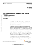
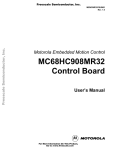
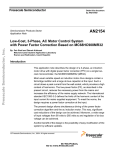
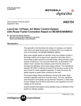
Order this document
by AN1712/D
Motorola Semiconductor Application Note
AN1712
"Get Your Motor Running" with the MC68HC708MP16
By David Wilson
Motorola Field Applications Engineer
Milwaukee, Wisconsin
Introduction
The quality of life we enjoy today can easily be correlated to the
existence of the electric motor. Indeed, many of the products in our
homes either have motors in them or a motor was used to manufacture
them. For instance, we counted 114 motors in our house alone, not
including our cars or the kids' toys.
However, the plethora of these electro-mechanical marvels in our
society constitutes an insatiable appetite for electrical energy. According
to the U.S. Department of Energy, 58% of the electricity generated in the
United States is consumed by electric motors[1], and no relief is in sight.
With a focus on energy consumption and environmental issues,
companies are scrambling for ways to put these motors on a "diet." One
solution which is becoming more and more palatable is electronic
control. If motor energy consumption continues along present trends,
the crucial question in the near future will not be "can we afford electronic
control," but rather, "can we afford not to have electronic control."
The explosive growth of power semiconductors and processor
technology within the last decade has made electronic control of all
motor types more economically feasible. Microcontrollers in particular
have enjoyed a recent upsurge in popularity for motor control
© Motorola, Inc., 1997
AN1712
Application Note
applications. As more control loops are implemented digitally, control
techniques which would have been difficult or impossible with analog
circuitry (such as adaptive control) are becoming commonplace.
Smarter fault management, variable frequency waveform generation,
and communications with other systems are all benefits brought to the
motor control arena by the microcontroller. Also, feature enhancements
on motor drives in production can often be handled by software
upgrades without having to "rev" the board layout. In fact, one
manufacturer of motor drives cleverly manages its inventory by building
a hardware unit which is used across several drive products. Different
control software running on this common hardware platform
distinguishes one product from another.
Once the decision has been made to use a microcontroller in a motor
control system, the engineer is faced with the formidable task of
selecting which one is best suited for the job. In many cases, for
instance, the CPU may be ideally suited for the particular motion control
task, but important features are missing in the embedded peripherals,
forcing the designer to add more hardware to compensate for the
deficiency. Or perhaps the peripherals are just right for the application,
but the CPU is oversized or lacking in development support. In many
cases, the designer settles on a DSP (digital signal processing) solution,
only to find that it executes the digital filters with time to spare, but is
difficult to program for the rest of the routines. In fact, many engineers
have related that more than 90% of their motor control code is "nonDSP" related, and that the CPU’s data management features can be
more important than its DSP features.
If you have struggled with any or all of these issues, then please read on.
Engineers at Motorola have "come together, right now" to address these
concerns with the new MC68HC708MP16, which can get just about any
motor running (unless it runs on gasoline, in which case you're reading
the wrong paper). The 'MP16 has been specifically designed to meet the
requirements for low-cost DC servo and AC "open loop" systems (see
Figure 1).
AN1712
2
MOTOROLA
Application Note
Introduction
4
2
5
TIM4
10
8 BIT A/D
CONVERTER
SPI
SCI
LVI
3
TIM2
PWM 1
PWM 2
16K ROM/EPROM
IRQ1
RESET
CPU 08
SIM
512 BYTES RAM
PWM 3
PWM 4
PWM GENERATOR
CGM
PWM 5
PWM 6
GENERAL PURPOSE I/O
64-PIN QFP
13
FAULT INPUTS
CURRENT POLARITY PINS
Figure 1. HC08MP16 Block Diagram
Anyone who has worked with the popular HC05 Family of
microcontrollers will appreciate the rich enhancements to the instruction
set provided by the CPU08 while at the same time maintaining object
code compatibility with its HC05 parent. Other enhancements such as a
16-bit index register and stack pointer, 5-cycle multiply instruction, and
high-level language support (C language) make the CPU08 ideally
suited for most motion control applications.
Another distinguishing feature of the 'MP16 is its powerful PWM
generator module, which can be configured and partitioned in a variety
of ways for different motor control applications. Figure 2 offers a more
detailed view of this module, which will serve as the focus for much of
this application note.
AN1712
MOTOROLA
3
Application Note
OR
BUS CLOCK
PRESCALER
UP/DOWN
COUNTER
÷ 1, 2, 4, OR 8
TRIGGER
PRESCALER
PWM RELOAD AND INTERRUPT
÷ 1, 2, 4, OR 8
PWM
GENERATORS
COMPARATORS
DOUBLE
BUFFERED
REGISTERS
CONTROL
PWM MODE
SELECT
INTERRUPTS
FAULT
PROTECTION
OUTPUT
FAULT
PARTITIONING
POLARITY
CONTROL
DEAD-TIME
INSERTION
PWM1
PWM2
PWM3
FAULT MODE
SELECT
DIRECT
OUTPUT
CONTROL
HIGH
CURRENT
DRIVERS
DISTORTION
CORRECTION
PWM4
PWM5
PWM6
MOTOR CURRENT POLARITIES
SYSTEM FAULTS
Figure 2. PWM Module Block Diagram
AN1712
4
MOTOROLA
Application Note
PWMs Designed for Your System, not Vice Versa
PWMs Designed for Your System, not Vice Versa
As alluded to earlier, a leading cause of frustration and consternation for
motor control design engineers is finding that the pulse width modulator
(PWM) requirements needed for the motor drive are incompatible with
the PWM capabilities of the selected microcontroller. As a result, you're
left with this big hole in the middle of your schematic that needs to be
filled with an assortment of gates and glue and buffers and so on.
The 'MP16 was designed from a system point of view in an effort to
minimize as many of these incompatibilities as possible, while keeping
the cost for this flexibility low. After analyzing many of our customer's
different motor control applications, Motorola soon discovered that a
large number of them had similar requirements which could be
addressed by enhancing the flexibility of the PWM module. Some of the
'MP16 features that account for this flexibility are discussed next.
Living on the Edge or in the Center
The 'MP16 can generate one of two types of PWM signals from the PWM
module at any given time from the PWM module — edge-aligned or
center-aligned — determined by the state of the EDGE bit in the
CONFIG register. Figure 3 shows both waveform types where the
vertical line represents a waveform alignment reference. The counter
value (represented by the bold traces) is shown being digitally compared
against two levels which are determined by the PWM VALUE registers,
and represent desired pulse widths. The PWM signals shown are the
result of those comparisons. To prevent erroneous pulse widths while
the software is loading new pulse width information, the PWM VALUE
registers are all double buffered. This information is picked up by the
PWM generator at the beginning of every one, two, four, or eight PWM
cycles, determined by how software loads the LDFQ0 and LDFQ1 bits in
PWM control register 2.
AN1712
MOTOROLA
5
Application Note
MODULUS = 16
ALIGNMENT
REFERENCE
EDGE ALIGNED
MODULUS = 8
CENTER ALIGNED
Figure 3. PWM Waveform Types
The counter in the PWM module counts from $000 hex to the value
specified in the PWM counter modulo register (up to $FFF maximum),
where each counter "tick" can be as fine as 125 ns for an 8-MHz bus.
The PWM x VALUE registers each hold a 16-bit value partitioned as an
upper byte and lower byte. As long as bit 15 of this value is clear
(indicating a positive number), the number is compared to the counter
value to generate the desired pulse width. Any value greater than or
equal to the counter modulus will result in a PWM signal with a full 100%
duty cycle. However, if bit 15 is set (indicating a negative number), the
value will instead be treated as 0, resulting in a duty cycle of 0%. That's
right. Zero. Zip. Nada! This automatic "saturation mode" of operation
permits overmodulation of the motor waveform which might result from
small finite word length errors, guaranteeing rail-to-rail operation without
having to deal with modulo wraparound at 0. Otherwise, the software
would have to check each PWM value and branch if it was less than 0 to
load a 0 value instead. This mode of operation can be compared to the
way an op-amp output works when you overdrive its input. It just
saturates instead of driving to the other rail.
AN1712
6
MOTOROLA
Application Note
Together, or not Together . . . That is the Option
From an inspection of Figure 3, it may be difficult to see why one PWM
waveform is preferred over another in a motor control application. If
you're looking for the best resolution possible at a given PWM frequency,
consider using edge-aligned mode. Figure 3 shows that for the same
PWM waveform period, edge-aligned operation allows the counter
modulus to be twice as high as that of center-aligned mode, thereby
doubling the PWM resolution. However, for most motor control power
stages that use multiple half bridge transistor arrangements, the benefits
resulting from the interaction between center-aligned PWMs justify their
selection. More on this later.
Together, or not Together . . . That is the Option
The 'MP16 PWM module can generate up to six independent PWM
signals, all synchronized to the same counter/timer. If that isn't enough,
three additional PWM signals can be obtained from the timer modules,
two of which are synchronized to a separate time base, and the third
synchronized to still another time base. In other words, a total of nine
independent PWM signals are possible from the 'MP16, running at up to
three different PWM frequencies.
Figure 4 shows the familiar IGBT half bridge used with many motor
drives. In some instances, it is desirable to control these devices in a
complementary fashion such that when one device is on, the other is off,
and vice versa. However, if power is applied across the half bridge, you
never want to have both transistors on at the same time, since fire,
smoke, and other unpleasantries may result.
To drive the transistors in a complementary fashion, the 'MP16 provides
a separate operating mode specifically for this purpose. By setting the
INDEP bit in the CONFIG register to 0, the six PWM signals are
configured as three pairs of complementary PWMs. This is extremely
useful when controlling a 3-phase power module, such as the
VersaPower module available from Motorola and shown in Figure 5.
AN1712
MOTOROLA
7
Application Note
V+
i+
i≠ –
V–
Figure 4. IGBT Half-Bridge Circuit
Incidentally, the VersaPower module comes in several different package
configurations such as the 24-pin package shown, which houses the offline input rectifiers, six inverter IGBTs, a brake transistor, and a
temperature sensor. A 16-pin package containing just the output power
section is also available. One, two, and three horsepower devices are
planned.
It is not sufficient for the bottom IGBT PWM signals to simply be inverted
versions of the top IGBT PWM signals. Due to delay uncertainties in the
IGBTs and the supporting circuitry, it is necessary to have a "dead-time"
inserted between the turn-off of a given IGBT and the turn-on of its
complementary device to guarantee no overlapping "on" times. The
'MP16 provides this dead-time insertion automatically with each PWM
transition in complementary mode, thus eliminating the need for external
timing circuitry. The dead-time for all PWM signals is specified as a
single 8-bit value representing the number of CPU clock cycles per
dead-time interval. For an 8-MHz bus, this implies a dead-time range
from 125 ns to more than 30 µs. For IGBT motor drives under 10 HP,
typical dead-time values range anywhere between 2 µs to 10 µs.
AN1712
8
MOTOROLA
Application Note
Together, or not Together . . . That is the Option
BRAKE RESISTOR
U
MOTOR
OUTPUT V
W
R
3 PHASE INPUT
S
T
1
2
3
4
5
6
7
8
9
10
11
12
D7
D8
D1
Q1
D3
Q3
D5
D10 D12
Q5
D9 D11 D13
D2
Q2
D4
Q4
D6
TEMP SENSE
D14
Q6
Q7
24
R1
23
22
21
20
19
18
+
17
16
15
14
13
C1
R NTC
FILTER
SENSE RESISTOR
2.02”
3.90”
4.39”
Figure 5. Complete 3-Phase Integrated Power Module from Motorola
AN1712
MOTOROLA
9
Application Note
Do It with More Power!
Having opto-isolators in the PWM signal path is common, especially for
the high-side transistors. The chosen opto should be fast and have a
high enough common mode dv/dt rating to prevent noise from appearing
on the PWM signals. One such opto that is well suited for high-voltage
motor drive PWM applications is the HCPL-0453. Like many other optos,
high light-emitting diode (LED) currents (approximately 15 to 20 mA) are
often required to achieve optimal performance, depending on the
circuitry connected to the opto's output. The 20-mA current sink
capability of the 'MP16 was designed with this requirement in mind.
Figure 6 illustrates an optically isolated high-side gate driver circuit
utilizing the 'MP16 to drive the opto-isolator directly.
2.2
+18 V
MC33153
5.6 K
VCC
DESAT
+5 V
FAULT
100
OUTPUT
HCPL0453
INPUT
10 µF
0.1 µF
SENSE
GATE
22
GND
VEE
EMITTER
180
HC08MP16
PWM1
PWM2
PWM3
Figure 6. PWM Buffer Circuit Using an Opto-Isolator
AN1712
10
MOTOROLA
Application Note
High or Low PWM Outputs: Whatever Turns You On
High or Low PWM Outputs: Whatever Turns You On
By the time the PWM signal makes its journey through the optos and
gate drivers, it may arrive at the power device with the wrong polarity.
This can really be annoying, especially if extra hardware is required just
to invert the PWM signals.
With the 'MP16, the polarity can be specified for the odd numbered PWM
signals independently from the even PWMs. It is assumed that the odd
numbered PWMs will be used to control the top transistors in a drive, and
the even numbered PWM signals will control the bottom transistors. The
bits TOPNEG and BOTNEG in the CONFIG register allow the software
to invert the top and bottom PWM polarities respectively. This is also
useful when interfacing a new microcontroller board to an existing power
stage with established PWM polarity requirements.
When the 'MP16 is first powered up or reset, the PWMEN bit in the
PCTL1 register is 0, and the PWM pins assume a high-impedance state.
If an opto is driven directly from a PWM output, a polarity convention,
therefore, should be established where no LED current corresponds to
the "off" condition. During this high-impedance time, the software must
program the correct polarity information into the CONFIG register before
enabling the PWMs by setting the PWMEN bit. Once this bit is set, all
PWM outputs will exit the high-impedance state and be negated for one
CPU clock cycle before being driven in accordance with the values
programmed in the PWM module. From that point on, if the processor
shuts down the PWMs for any reason, they will be quickly driven to the
"off" voltage level instead of floating, since the processor now knows
which voltage level is "off."
AN1712
MOTOROLA
11
Application Note
Development Tool Compatibility
When using the development equipment with some motor control
micros, extreme care must be taken or damage may result to the motor
and the drive under development. For example, when a break point is
encountered in the code stream, some micros just leave the PWMs on
with their present pulse width, or worse, freeze the PWMs in their
present states. For many motor types (including AC induction motors),
either of these conditions causes the motor to stop abruptly, resulting in
potential damage to the motor drive.
The 'MP16 was designed to take emulation tool support into
consideration by negating all of the PWMs (driving them hard off) under
break conditions. This disables the power stage, resulting in the motor
coasting safely to a stop.
Whose Fault is It?
Most motor drives on the market today have earned a reputation for
being robust and "bulletproof" thanks in large part to their fault tolerance.
Sensing of such parameters as bus voltage, heat sink temperature, and
over-current conditions as means of protection are becoming more and
more commonplace. Signals representing these parameters are often
supplied to an analog-to-digital (A/D) converter and then regulated by
software. However, if corrective action is required immediately, software
alone is often inadequate to provide the necessary protection. For this
reason, such system parameter signals are often compared in hardware
against a threshold that represents an unacceptable level, and fault
signals are created to disable the drive immediately. Therefore, the
drive's microcontroller should have the capability to process these
signals, and immediately disable the PWM outputs when a fault
condition is present.
However, most microcontrollers on the market today can accommodate
only one fault signal, requiring the hardware designer to include extra
circuitry just to gate all the fault signals together. It is left up to the
software engineer to figure out which signal is responsible for the fault.
AN1712
12
MOTOROLA
Application Note
Whose Fault is It?
It is even more frustrating if the offending fault has disappeared by the
time the software responds. This may not foster feelings of harmony and
good will between the software and hardware engineers.
To simplify the hardware design task, the 'MP16 has four fault inputs that
are connected directly to the PWM module to immediately disable its
outputs. These inputs are evenly split into two banks that can be
programmed to disable different PWM outputs. This allows the 'MP16 to
control up to two independent power stages, each with their own fault
feedback signals. Examples of this are presented later.
The software engineer will appreciate the fact that each fault input has
its own interrupt vector, allowing a separate interrupt service routine to
be executed for each fault condition without having to poll separate
input/output (I/O) inputs to determine what caused the fault. In addition,
the CPU is capable of reading the immediate status of the fault inputs via
the FPINx bits in the fault status register (FSR).
All fault inputs work identically in terms of how they disable the PWM
outputs. When a fault occurs, the corresponding PWM outputs are
disabled immediately. When and how they become enabled again is
dependent on which operating mode is in effect for that fault input. Each
input can be programmed to work in either manual mode or automatic
mode, both of which are described in this application note.
Take Control
in Manual Mode
In manual mode, the software is responsible for reactivating the PWM
outputs. However, when this mode is selected, the odd numbered fault
inputs work differently than the even numbered inputs. For an odd
numbered fault, the affected PWMs will be reactivated on the next PWM
cycle after the software has acknowledged the fault by clearing the
associated FTACK bit in the FTACK register. The software assumes full
responsibility for PWM enabling, and the PWMs will come back on line
even if the fault is still asserted. This is useful for processing faults that
may have a long time constant or hysteresis associated with them, but
the PWM outputs are still required to be active during the time it takes
the fault signal to negate.
AN1712
MOTOROLA
13
Application Note
The even numbered fault pins work almost the same way except that the
PWMs will be enabled on the next PWM cycle after the software has
acknowledged the fault and the fault signal is negated. This provides
ultimate protection, even for the condition where the FTACK bit may
have been accidentally cleared (for instance, runaway code). Another
application would be when the software has granted PWM enabling by
clearing the FTACK bit, but in the meantime wants the PWMs to remain
disabled until the fault input is negated. At that point, the PWMs will
come back on line automatically. An easy way to remember the
difference between the odd and even fault pins is to think that the even
pins provide even more protection.
Take It to the Limit
in Automatic
Mode
Automatic mode is a unique operating mode where the PWM outputs
can be turned back on automatically at the start of the next PWM cycle,
assuming that the offending fault has gone away. The primary
application for this mode of operation is cycle-by-cycle current limiting,
as illustrated in Figure 7. A resistor inserted in series with the motor
develops a voltage when current is flowing through the motor. This
voltage is compared to a threshold representing a safe upper current
limit, and the comparator output constitutes the fault input signal. The
dashed portion of the PWM waveform indicates the normal duty cycle
that would have occurred without current feedback. The solid line shows
early termination of the PWM signal's "on" time resulting from the current
threshold being reached. Cycle-by-cycle current limiting allows the
motor current to be regulated automatically by the protection hardware
of the 'MP16, thus freeing the software to focus on other control tasks.
AN1712
14
MOTOROLA
Application Note
Whose Fault is It?
FROM AMPLIFIER
MOTOR CURRENT
SAFE THRESHOLD
+
-
TO MP16 FAULT INPUT
PROGRAMMED FOR AUTOMATIC MODE
SAFE THRESHOLD
MOTOR CURRENT
FAULT SIGNAL
PWM
Figure 7. Cycle-by-Cycle Current Limiting
AN1712
MOTOROLA
15
Application Note
You Can Bank on It
BIT 7
BIT 6
BIT 5
BIT 4
As was mentioned earlier, the four fault inputs are segregated into two
separate banks. Fault inputs 1 and 2 are combined with software bit
DISX in the PCTL1 register to constitute the disable for bank X, while
inputs 3 and 4 are combined with the DISY bit in the PCTL1 register to
create the disable for bank Y. These signals are then presented to the
disable mapping logic shown in Figure 8, which allows each disable
signal to negate some or all of the PWM outputs.
BIT 3
BIT 2
BIT 1
BIT 0
DISMAP $0037
DISABLE
PWM1
BIT 7
BIT 6
DISABLE
PWM2
BIT 5
BANK X
DISABLE
PWM3
BIT 4
BIT 3
DISABLE
PWM4
BANK Y
BIT 2
BIT 1
DISABLE
PWM5
BIT 0
DISABLE
PWM6
Figure 8. PWM Disable Mapping Logic
AN1712
16
MOTOROLA
Application Note
Whose Fault is It?
To illustrate how the disable mapping logic can be used, refer again to
Figure 5 and Figure 6. With drives that contain high-side gate driver
circuits as shown in Figure 6, it is sometimes useful to PWM the lower
transistors while the upper transistors remain disabled at initialization
time to charge pump the gate drive power supply capacitor. This may be
accomplished by programming $B6 in the DISMAP register, which
allows bank X to disable all the transistors while bank Y disables only the
upper transistors (assuming that the odd numbered PWM outputs are
used to drive the upper transistors). Configured as such, any fault
conditions that would require shutdown of all PWM outputs would use
fault pins 1 or 2, since they are channeled into bank X. By specifying the
state of the DISY bit in the PCTL1 register, the software can selectively
enable and disable the upper transistors without affecting the lower
transistors.
The fault partitioning scheme also is useful when the 'MP16 is called
upon to control two separate power stages simultaneously, such as a
converter/inverter combination, or two DC motor H-bridges. An example
of this is included in this application note.
AN1712
MOTOROLA
17
Application Note
Be Direct
On occasion, software may need direct control over the PWM outputs.
For example, when the drive is first powered up or reset, software may
perform drive diagnostics where each power device is controlled
individually. In such instances, the user will find the PWM output control
port to be a useful feature on the 'MP16.
By setting the OUTCTL bit in the PWMOUT register, the PWM generator
is disconnected from the output pins, even though it continues to run.
PWM outputs are then controlled directly by bits OUT1–OUT6 in the
PWMOUT register.
However, unlike ordinary I/O ports, the PWM output control port provides
two protection features for the drive hardware:
•
Dead-time is still active for complementary outputs if
complementary mode is enabled. For example, there is no way to
have both PWM1 and PWM2 active at the same time nor to have
the dead-time between the assertion of one and the negation of
the other to be violated.
•
The OUTx bits do not control the actual voltage level at the PWM
pins; only whether they are asserted or negated. The polarity
convention established by the TOPPOL and BOTPOL bits is still
in effect.
Again, the thinking is to prevent accidental damage to the drive
hardware in the event of runaway code (or a temporary moment of
insanity exhibited by the software engineer).
A table showing output performance for OUTx bit conditions is located in
the user's manual for both complementary and independent modes of
operation.
AN1712
18
MOTOROLA
Application Note
It Takes a Licking . . . Keeps on Ticking
It Takes a Licking . . . Keeps on Ticking
Since the processor's oscillator circuit literally is the heartbeat of the
entire system, care must be taken to ensure that it is functioning properly
at all times. As of the time of this writing, at least one European
regulatory agency is considering a dead-oscillator test on a running
machine to observe the failure mode.
The clock generation module (CGM) on the HC08 Family has been
specifically designed to withstand the rugged requirements of industrial
applications. To this end, a phase-locked-loop (PLL) has been
implemented in the silicon, which yields a twofold advantage for
industrial applications:
1. The clocking circuit is much more immune to noise spikes on the
crystal input. This is an important feature when considering that in
many motor drives, the processor is located very close to the
power switching devices. With the 'MP16, any noise spike on the
crystal input pin will be interpreted as a change of the input
frequency by the PLL, which will slowly adjust its output frequency
in the direction of the perceived frequency change. On a
processor without a phase-locked-loop, the noise spike could
cause a timing violation in the CPU state sequencer, which in turn
could crash the processor.
2. The PLL has a special bit called the LOCK bit that can generate a
CPU interrupt informing it if phase lock has been lost. At this point,
the processor can test the crystal integrity via the crystal loss
detect bit and respond gracefully to the situation, taking the
appropriate actions. Note also that even if the external clock input
is lost completely, the PLL will continue to run at a frequency of
roughly one-third the VCO's center-of-range frequency.
AN1712
MOTOROLA
19
Application Note
Load ’Em and Leave ’Em
The 'MP16 relies heavily on "write-once" registers as the cornerstone to
its output protection strategy. Many programmable features such as the
PWM output polarities are actually fixed system parameters that should
not require changing once they are specified. Without such protection, if
the polarities are changed inadvertently by a software bug or runaway
code after being correctly loaded, the software engineer could be forced
into the awkward position of having to inform the hardware engineer that
his or her board has blown up.
In the spirit of increasing motor drive longevity, Motorola has designated
as write-once registers some of these registers that could affect the
protection integrity. For instance, the software may write to them only
one time after each reset.
These registers and their addresses are:
Configuration Register
Dead-Time Register
PWM Disable Mapping Register
(CONFIG)
(DEADTM)
(DISMAP)
$001F
$0036
$0037
Application Examples
Despite the wide diversity of motor types available today, it may come
as quite a surprise to realize that most motors work pretty much the
same way. For example, torque is developed in an AC induction motor
the same way it is in a DC motor. This realization led Felix Blaschke, a
researcher at Siemens, in 1968 to pioneer the concept of field orientation
with induction motors[2]. Even the stepper motor (which is often
inappropriately described as a "digital" motor) is really an analog motor
that develops torque the same way as other motors.
The design of the 'MP16 PWM module capitalizes on these similarities,
which allows it to control many different types of motors. A few examples
illustrating this point are given here.
AN1712
20
MOTOROLA
Application Note
Application Examples
Low-Cost, V/Hz
Induction Motor
Controller
The torque produced by a common AC induction motor is shown in
Figure 9 as a function of motor shaft speed. A typical HVAC load also is
plotted for comparison. Even though the induction motor is an
asynchronous motor, it still tries to run at a speed close to its input
frequency, as evidenced by the steep slope of the speed-torque curve at
the load intersection point. As the amplitude of the voltage sine wave(s)
applied to the motor decreases, the motor's speed-torque curve will be
attenuated, permitting a limited range of variable speed operation. This
method of speed control is very load dependent, however, and is
generally not used, especially with NEMA type A or B motors which have
a steeper speed-torque slope. The more generally accepted practice is
to vary the frequency of the AC waveforms to the motor, resulting in the
motor curve in Figure 9 shifting either right or left depending on the
direction of the speed change.
Since electric utilities are reluctant to change the frequency they
generate, DC motors ruled supreme in variable speed applications for
decades, even though AC motors are more reliable and in some cases,
up to six times cheaper. But this situation has changed today with the
advent of the induction motor variable speed drive (VSD), which can
produce power sine waves at continuously variable frequencies. In the
'MP16, this is accomplished easily by defining a digitized sine wave
TORQUE
INDUCTION MOTOR
TYPICAL LOAD
SHAFT SPEED
STATOR FREQUENCY
Figure 9. Speed-Torque Curve for an Induction Motor
and a Typical Load
AN1712
MOTOROLA
21
Application Note
look-up table in the processor's memory and spooling data out of this
wave table to the PWM generator to create different frequency sine
waves, as illustrated in Figure 10. For low-cost, open-loop applications,
the input variables to the PWM routine are simply the desired voltage
and frequency to be applied to the motor. The functions shown would
typically exist as an interrupt service routine initiated by a periodic
interrupt from the PWM module. In fact, the PWM module can be
programmed to provide this interrupt at a rate of every one, two, four, or
eight PWM cycles to accommodate the time required to execute the
interrupt routine.
To generate a 3-phase output, the data for phase one is fetched from the
wave table at a location corresponding to the pointer position calculated
by the integrator. A value is then added to the pointer, resulting in a shift
of 120 degrees (85.33 points for a single-cycle table of 256 points), and
the data for phase two is indexed. If the pointer is incremented to an
WAVEFORM TABLE
1050
1000
WAVE (θ)
800
WAVE (θ + 2 π/3)
600
S4
400
WAVE (θ + 4 π/3)
200
0
–26 0
50
100
150
200
250
θ
F
INPUTS
TO
ISR
INTEGRATOR
SINE TABLE POINTER
X
V
PWM1 VALUE REGISTER
PWM3 VALUE REGISTER
X
X
PWM5 VALUE REGISTER
Figure 10. PWM Generation Technique
AN1712
22
MOTOROLA
Application Note
Application Examples
address beyond the end of the table, take care to ensure that the pointer
wraps to the beginning of the table. This will be handled automatically by
the modulo arithmetic associated with the pointer increment if the
number of entries in the wave table is sized to match the pointer word
length. Phase three data is obtained by a further 120-degree increment
of the pointer.
This technique supports bidirectional motor operation by controlling the
sign of the frequency variable. Negative frequencies result in reverse
shaft rotation, and the pointer simply is decremented by the integrator
instead of incremented. Again, if the wave table is sized to match the
pointer wordlength, the modulo arithmetic automatically will handle the
required wrap-around when the pointer is decremented beyond the
beginning of the table.
Code has been written for the 'MP16 which executes the functions
shown in Figure 10 in 33 µs for an 8-MHz bus. To put this in perspective,
the 'MP16 could generate 10-kHz PWMs for a 3-phase motor, updating
all the PWM values at the start of each new PWM cycle, and still have
66% CPU bandwidth remaining for other tasks.
Since AC motor control is the target application of the 'MP16, one can
reasonably expect that the part is ideally suited to this task. A typical
hardware configuration is shown in Figure 11. The DISMAP register
retains its default value of $FF, which allows a fault condition on any of
the fault inputs to disable all the PWM outputs. All fault inputs are
programmed to work in manual mode, and the current fault uses the
fault2 input, which means the software must acknowledge the fault and
it must go away before the PWMs can be reactivated. The temperature
and bus voltage faults are returned to the odd-numbered fault pins,
which implies that the fault still can be asserted when software
reactivates the PWMs. This permits these signals to have long time
constants and/or hysteresis.
Since each of the six inverter transistors is driven with a unique PWM
signal, the full advantages of center-aligned operation can be realized.
Also, complementary mode should be specified and a dead-time value
written to the dead-time register before the PWMs are enabled.
AN1712
MOTOROLA
23
Application Note
BUS
CURRENT
PROCESSING
TEMPERATURE
PROCESSING
BUS
VOLTAGE
PROCESSING
VERSAPOWER
U3
R9
C3
TO AC MOTOR
JP2
R7
R29
J3
R30
R23
R21
R25
U12
R19
C10
JP3
U5 R11
J2
U9
U1
J1
R31 R32
R26
U10
U11
U6
R12
C4
U4
R8
U7
U2
U8
R2
C2
R1
C1
JP1
HIGH VOLTAGE
MICRO TO MOTOR INTERFACE
ITC132
FAULT2
PWM1
PWM2
PWM3
PWM4
PWM5
PWM6
ATD0
FAULT3
ATD1
FAULT1
HC708MP16
ATD2
Figure 11. Low-Cost 3-Phase AC Motor Control System
Split-Phase Induction Motor Controller
The split-phase induction motor is a polyphase motor with its windings
spatially separated by 90 electrical degrees. By supplying quadrature
current waveforms to the two windings, motor rotation is achieved with
less torque ripple than that attainable with a single-phase induction
motor with a start winding. This is commonly achieved by putting a large,
non-polarized capacitor in series with one of the windings and powering
both phases from the same single-phase supply. Rotational direction is
determined by which phase is connected in series with the capacitor.
AN1712
24
MOTOROLA
Application Note
Split-Phase Induction Motor Controller
Figure 12 shows a simple power circuit that can achieve the quadrature
waveforms without the capacitor in series with the motor winding. By
using the 'MP16 to control the PWMs to the four transistors, precise
quadrature current waveforms can be created that will allow the motor to
rotate in either direction at variable speeds. As can be seen, this
technique results in a simpler converter/inverter power configuration
than its 3-phase counterpart. The 'MP16 PWM module would be
programmed for complementary operation between the odd and even
numbered PWMs, and the dead-time would be programmed just like the
3-phase motor control example. A software lookup table could also be
used in the manner described in the last section to generate the
waveforms for both phases.
PWM1
PWM3
cos(ωot)
SINGLE
PHASE
AC
cos(ωot ± π/2)
PWM2
PWM4
ING
A
ND
WI
SQUIRREL
CAGE
ROTOR
WI
ND
ING
B
Figure 12. Variable Speed, Split-Phase Motor Controller
AN1712
MOTOROLA
25
Application Note
Switch Reluctance Motor Control
Although the principle of switch reluctance (SR) motors has been around
since 1838, only recently have they moved into the spotlight, thanks in
large part to the economic benefits obtained by lower-cost electronic
control. The advantages claimed by these motors are quite impressive.
For example, one SR motor manufacturer is already claiming a 10%
reduction in manufacturing costs compared to an induction motor of the
same horsepower rating. This number is expected to improve as the
manufacturing infrastructure for these motors is put in place. Combined
with its rugged construction (no rotor conductors or magnets) and boasts
of greater efficiency and speed range, SR motors pose some interesting
possibilities down the road.
Of course, you don't get something for nothing. And with SR motors, the
price to be paid is no direct on-line capability (Electronics are needed to
commutate the motor.) and increased torque ripple and audible noise
resulting from the doubly salient design of the rotor and stator. By using
the PWMs on the 'MP16, the current in each phase can be profiled and
overlapped with the current in other phases to provide smoother and
quieter operation.
Consider the configuration in Figure 13. Such a circuit would control a
4-phase SR motor, the most common being the 8-stator pole, 6-rotor
teeth design with a 15-degree stroke. It is interesting to note that the
same circuit can provide chopper control of a 4-phase stepper motor.
The 'MP16 controls which phases are energized at any given time by
measuring the motor shaft position and using four of its general-purpose
outputs to turn on the appropriate bottom transistors. The top transistors
are controlled from the PWM generator. In this application, it is assumed
that only one motor phase from a given pair will be on at a time.
AN1712
26
MOTOROLA
Application Note
Switch Reluctance Motor Control
D3
D5
VOLTAGE
PROCESSING
CIRCUITRY
FAULTS 1 & 3
D4
D6
GPIO3
GPIO1
PWM 6
PHASE 4
PHASE 3
PHASE 1
D2
PHASE 2
PWM 1
D1
CURRENT
COMPARATOR
PHASES 1/3
GPIO2
FAULT 4
GPIO4
CURRENT
COMPARATOR
PHASES 2/4
FAULT 2
Figure 13. 4-Phase Switch Reluctance Motor Control Power Stage
By programming the even numbered fault pins to operate in automatic
mode, independent cycle-by-cycle current limiting is obtained for each
pair of phases. For this to work, the DISMAP register is programmed
with $00 (or any value that ensures that PWM1 is affected only by fault
inputs 3 and 4, and PWM6 is affected only by faults 1 and 2). When
current limiting occurs, the upper transistor associated with that pair of
phases is turned off, but the bottom transistor remains on to allow
smooth freewheeling of the current through either D5 or D6. Current is
extinguished in a given phase by turning off both the top and bottom
transistors associated with that phase, forcing current commutation back
through the DC supply.
If a bus over-voltage occurs, all motor phases must be disabled. This
implies that the voltage processing circuitry must use two fault inputs,
one to disable PWM1 and one for PWM6. Both of these fault inputs
would be programmed to operate in manual mode.
AN1712
MOTOROLA
27
Application Note
Since the motor phases are connected between the top and bottom
transistors, dead-time insertion is not required. Operating in
independent mode with edge-aligned PWMs would thus be a logical
selection, yielding a PWM resolution of 125 ns for a bus frequency of 8
MHz.
Figure 14 shows typical current waveforms for a 4-phase SR motor[3].
Waveshaping could once again be obtained using a waveform table as
described in the application section on induction motors. To preserve
processor bandwidth, the software can elect to disable current
waveshaping at higher RPMs in favor of a simpler "stepper" type of
control scheme.
PHASE 1
PHASE 2
PHASE 3
PHASE 4
90 DEGREES
Figure 14. Typical Current Waveforms of a 4-Phase SR Motor
Multiple DC Motor Control
The PWM module in the 'MP16 has been designed to accommodate
more than one power stage, as shown in the example in Figure 15. For
this configuration, the DISMAP register would be programmed to $44
hex. Since the fault logic is comprised of two separate banks, the current
in each motor can be controlled independently on a cycle-by-cycle basis
by programming fault inputs 2 and 4 for automatic mode. A bus overvoltage could be caused by either motor, so the voltage-sensing circuitry
must be connected in such a way that an over-voltage fault disables both
banks of PWMs.
AN1712
28
MOTOROLA
Application Note
Multiple DC Motor Control
VBus
PWM1
PWM2
PWM5
PWM6
MOTOR
1
PWM2
MOTOR
2
PWM6
PWM1
PWM5
HC708MP16
VALUE
VOLTAGE
PROCESSING
TRIP
ATD1
FAULT1
FAULT3
CURRENT
PROCESSING
VALUE
LIMIT
VALUE
CURRENT
PROCESSING
LIMIT
PWM1
PWM2
PWM5
PWM6
ATD2
FAULT2
ATD4
FAULT4
Figure 15. Dual H-Bridge Motor Control Configuration
In this example, complementary mode should be selected, and a deadtime value programmed into the dead-time register. Since both sides of
each H-bridge are driven by the same pair of PWM signals, there is little
advantage in specifying center-aligned PWM operation, especially since
edge-aligned operation yields twice the resolution for a given PWM
frequency. In the next example, the benefits of center-aligned PWMs are
demonstrated.
AN1712
MOTOROLA
29
Application Note
Figure 16 shows typical PWM waveforms for this drive configuration. In
preparation for the next example, notice that the motor terminal voltage
swings from +Bus to –VBus at a frequency equal to the PWM frequency.
PWM1
PWM2
+ VBus
MOTOR
– VBus
Figure 16. PWM Waveforms Resulting
From Edge-Aligned PWMs
High Performance Servo Controller
This application takes full advantage of the center-aligned PWM output
capability of the 'MP16. To do this, each transistor must be driven with
its own unique PWM signal, as shown in Figure 17. The motor current
is limited on a cycle-by-cycle basis by programming fault inputs 2 and 3
for automatic mode and driving them from comparators that monitor the
current in each leg of the H-bridge. Fault input 1 provides overvoltage
protection during regeneration by disabling the PWMs when the DC bus
voltage is too high. For this example, fault input 1 would be programmed
to operate in manual mode.
The software must generate two PWM values: one for the left side of the
H-bridge and one for the right side. If the average of both of these duty
cycles is 50%, something wonderful happens as shown in Figure 18.
First, the PWM frequency seen by the motor is twice that applied to each
transistor. This effect alone will reduce the motor ripple current by at
least 6 dB, assuming the frequency is higher than the pole formed by the
electrical time constant of the motor. Second, the peak-to-peak voltage
applied to the motor is half that of the previous example, reducing the
ripple current even further. Also, for the condition of near 0 volt motor
operation where servo requirements are the most stringent, the motor
AN1712
30
MOTOROLA
Application Note
High Performance Servo Controller
current is commutating effectively into a diode and a transistor drop
versus the bus supply as in the last example. This has the effect of
lengthening the time constant of the current commutation, which also
smoothes the current waveform. As might be expected, coreless rotor
designs and low-inductance motors in general stand to benefit from this
type of control.
HC708MP16
V BUS
VALUE
VOLTAGE
PROCESSING
PWM1
TRIP
ATD1
FAULT1
PWM3
VALUE
CURRENT
PROCESSING
MOTOR
LIMIT
PWM1
PWM2
PWM3
PWM4
ATD2
FAULT2
PWM4
PWM2
CURRENT
PROCESSING
VALUE
ATD3
LIMIT
FAULT3
74HC86
FILTERED
ENCODER
INPUTS CHANNEL A
ENCODER COUNT CLOCK
B
A
10K
↓ TCLKA
100 pF
VCC
20K
TCH3B
TCH2B
TCH1B
74HC86
S
C
D
74HC86
100 pF
Q
TCH0A
TCH0B
74HC74
D
VCC
UP/DOWN
↔
CHANNEL B
74HC86
Q
R
VCC
Figure 17. High Performance DC Servo Control
AN1712
MOTOROLA
31
Application Note
Recall that center-aligned PWM mode yields half the resolution for a
given PWM frequency compared to edge-aligned mode. However, by
judicious calculation of the two PWM values, this reduction in resolution
can be recouped for this application. Consider the "motor" waveform of
Figure 18. Each consecutive positive pulse has the same duty cycle
since the PWM 1 and PWM 3 value registers are programmed to
produce identical pulse widths.
What would happen if this were not the case? For example, suppose one
count is subtracted from the PWM 3 value register to produce a slightly
longer positive pulse width than that of the PWM 1 value register. The
effective high time over a PWM cycle (as defined by a complete up/down
cycle of the PWM counter) would be the average of these two widths. In
other words, the average pulse width would be in between that specified
by the PWM 1 and PWM 3 value registers, yielding a 1/2 count
resolution.
PWM3 VALUE REGISTER
50%
PWM1 VALUE REGISTER
PWM1
PWM2
PWM3
PWM4
GND
MOTOR
– VBus
PWM FREQUENCY AT MOTOR IS DOUBLED VOLTAGE SWING IS HALVED
MOTOR RIPPLE CURRENT IS REDUCED
Figure 18. Center-Aligned PWM Effect on Motor
AN1712
32
MOTOROLA
Application Note
High Performance Servo Controller
Resolution doubling as discussed above can be accomplished by using
these equations:
Where:
PWMx
PMOD
POL
PWM
PWM1 = INT (
PMOD
PMOD * PWM
+ 0.25 + POL *
2
2
)
PWM3 = INT (
PMOD
PMOD * PWM
+ 0.25 – POL *
2
2
)
= the value loaded into the appropriate PWM x value register
= the value in the PWM counter modulo register
= 1 or –1, depending on the desired motor voltage polarity
= the desired pulse width (fraction between 0 and 1)
These two equations have been designed to utilize the same terms to
minimize the number of calculations the software needs to perform.
Figure 19 shows a Mathcad® simulation of the equations for the
condition of PMOD = 20. The graph is plotted over the range
0 ≤ PWM ≤ 1.
20
PWMx VALUE REGISTER
PWM1
PMOD / 2
PWM2
0
0
PWM FRACTION VALUE
1.0
Figure 19. Example of Resolution Doubled PWMs
AN1712
MOTOROLA
33
Application Note
Encoder
Processing
With careful software design and moderate shaft speeds, encoder
signals can be decoded directly by the 'MP16 timers. In fact, Motorola
already is working on a software solution for this. For more demanding
applications, however, external hardware is required to process the
encoder signals, as shown in Figure 17. The circuitry shown decodes
encoder channel information into a count clock and an up/down signal[4].
Each new encoder position results in a count of the timer A counter. Any
change in the direction of rotation will cause an optional interrupt and a
capture of the timer A value corresponding to the first encoder count in
the opposite direction. Since the timer A counter only counts up, the
software is responsible for integrating the direction information when
calculating the encoder position. Figure 20 shows the timing
relationships for the encoder processing circuitry.
CHANNEL A
CHANNEL B
74HC86
A OUTPUT
74HC86
B OUTPUT
74HC86
C OUTPUT
UP/DOWN
POSITION
N
N+1
N+2
N+3
N+4
N+5
N+6
N+7
N+8
N+9
TIMER
COUNT
0
1
2
3
4
5
6
7
8
9
CAPTURED
VALUE
N+8
N+7
N+6
N+5
N+4
N+3
N+2
N+1
10
11
12
13
14
15
16
17
LAST VALUE OF DIRECTION CHANGE
10
TCH0B
TCH2B
TCH1B
TCH3B
Figure 20. Encoder Processing Waveforms
AN1712
34
MOTOROLA
Application Note
High Performance Servo Controller
Motor velocity data is often obtained by counting encoder pulses during
a given sampling period. This gives satisfactory results, assuming that
the motor velocity is high enough to yield many encoder counts per
sampling period. However, at slower speeds, the quantization noise
becomes much more noticeable since the velocity signal is so small.
Indeed, one can envision the scenario of an extremely slow motor where
the number of encoder counts per sampling interval is either 0 or 1. This
lack of resolution often results in erratic servo behavior at slower speeds
manifested by an audible "scraping" sound from the motor.
To mitigate this effect, many servo systems which synthesize velocity
information from the encoder will instead measure the period of the
encoder signals at slower motor speeds. In fact, the slower the rotation,
the higher the resolution of the period measurement. This value can then
be inverted and scaled in software to obtain a velocity signal with very
high resolution. The most accurate velocity information from an encoder
is obtained by measuring the time between similar edges on a given
signal, since the timing skew between the two encoder channels varies
as a function of the encoder angle. To ensure that the velocity
information is updated as frequently as possible, four timer channels are
used as seen in Figure 17, resulting in an update to the velocity
information every encoder count.
To buffer the signals coming from the encoder, the Motorola MC1489A
quad line receiver is an excellent choice for several reasons related to
the device’s noise rejection capabilities. First, the input threshold is rated
to work with TTL and CMOS level signals, but will continue to function
properly for input voltages up to 30 volts. Also, by connecting an
appropriately sized filter capacitor to the response control pin, the device
provides noise spike rejection. The rejection capability increases with
the capacitor size and is documented on the device’s data sheet. Finally,
the input provides about 1 volt of hysteresis, resulting in further noise
rejection.
AN1712
MOTOROLA
35
Application Note
Brushless DC Motor Controller
Figure 21 illustrates an example of how the 'MP16 can be used to
control a brushless DC motor. By connecting the Hall effect signals to
the 'MP16 timer inputs, some interesting control schemes become
possible. TCH0B through TCH2B are each programmed to perform an
input capture function on any edge for the three Hall sensor signals that
define the commutation intervals. When an edge is detected, an interrupt
is generated informing the CPU to change the waveforms to the motor.
In the interrupt service routine, the rotor position is determined by
examining the state of the TCH0B through TCH2B inputs. This is done
by reading the port E data register, which reflects the state of the input
pins even when they are being used by the timer. Once the rotor position
is determined, the 'MP16 can combine this knowledge with the desired
rotation direction information and apply the appropriate motor drive
signals, as illustrated in the example in Figure 22.
When a transition occurs on one of the Hall sensor signals, a time stamp
of the event is recorded in the appropriate channel register. This
information can be used to calculate accurately the speed of the motor
shaft. Recall that the speed of a rotating body is defined as:
dθ(t)
ω(t) = dt
AN1712
36
MOTOROLA
Application Note
Brushless DC Motor Controller
VBus
PWM 3
PWM 1
PWM 5
BRUSHLESS
MOTOR
PWM 6
CURRENT
PROCESSING
VALUE
LIMIT
HALL C
TCH2B
TCH0B
HALL B
FILTERING
TCH1B
PWM 4
HALL A
PWM 2
ATD0
FAULT1
TCH3B
SHUNT
RESISTOR
VOLTAGE
PROCESSING
VALUE
TRIP
+5 V
FORWARD/REVERSE
SPEED INPUT
PWM1
PWM2
PWM3
PWM4
PWM5
ATD1
FAULT3
PWM6
PTE3
ATD2
HC708MP16
Figure 21. Brushless DC Motor Controller
AN1712
MOTOROLA
37
Application Note
ROTOR ELECTRICAL POSITION (DEGREES)
0
60
120
180
240
300
360
HALL A
HALL B
HALL C
PWM1
PWM3
PWM5
PWM2
PWM4
PWM6
Figure 22. Brushless DC Motor Commutation Waveforms for Forward Direction[5]
AN1712
38
MOTOROLA
Application Note
Brushless DC Motor Controller
If the rotational speed over the previous commutation interval is
assumed to be constant, then the velocity over the last commutation
interval can be defined as:
ω=
∆θ
∆t
Where:
∆θ = the mechanical angle spanned by the last commutation
interval
∆t
= the time between the last two hall sensor signal transitions
If the commutation boundaries are evenly spaced, ∆θ is constant for that
particular motor, implying that the ∆t measurement is sufficient for
calculating velocity.
Once ∆t has been obtained, it is also possible to estimate the shaft
position at any time by using this equation:
θ̂(t) =
∆θ [t – tcap]
+ θtcap
∆t
Where:
θ̂ (t) = estimated shaft position at time "t"
∆θ = the mechanical angle spanned by the last commutation
interval
∆t
= the time between the last two Hall sensor signal transitions
t
= the present time obtained from reading the free-running timer
tcap = the captured time of the last Hall sensor signal transition
θtcap = the shaft position at the time of tcap (assumed to be a known
value)
Again, the assumption is made that the motor is spinning at a constant
velocity and the commutation boundaries are evenly spaced.
The equation can also be solved for t in cases where a certain action
must occur at a specified shaft position θ(t). This value can then be
placed in a timer channel to generate an output pulse or interrupt to the
CPU when the estimated position is reached (channel 3 is used in
Figure 21). A useful application of this is to perform phase advancement
of the commutation boundaries. Due to the electrical time constant of the
motor windings, it takes a certain amount of time during commutation for
the field to decay in the previous winding and become established in the
AN1712
MOTOROLA
39
Application Note
new one. This delay causes a shift in the rotor angle over which the
windings are energized. At slow speeds, the shift is minimal and typically
is ignored. At high speeds, by the time the field becomes established in
the winding, the rotor already has moved past the point where optimal
torque can be developed. The result is a second order reduction in motor
torque at higher speeds.
To compensate for this effect, the "on-time" angles of the windings can
be advanced in exactly the same way and for the same reason as a
spark advance on a gasoline engine. Assume that the desired
commutation advance (ψ) is specified as a fraction of the commutation
interval (for instance, 0 ≤ ψ ≤ 1). If count1 and count2 are the timer values
corresponding to the last two Hall signal transitions, the timer value
corresponding to the desired commutation angle can be estimated as:
countc = (count2 – count1) (1 – ψ) + count2
When the free-running timer value equals countc, the timer hardware
informs the CPU that it is time to change the waveforms to the motor.
HC08MP16 as a Smart Peripheral for Motor Control
A few applications may require more calculating power than the CPU08
is capable of (for instance, sensorless vector control). However, the
PWM module on the 'MP16 still can be used by programming the 'MP16
to act as a "smart" peripheral, as shown in Figure 23. In this case, the
program in the 'MP16 has a single function, that being to parse and
execute the commands sent to it from the host processor via its SPI
interface, which can clock data at a rate of 8 million bits per second.
These commands could be anything from generating a PWM output to
reporting an A/D input value. Incidentally, the SPI module is also useful
in stand-alone applications by using it in master mode to communicate
to off-chip peripherals that support the SPI interface standard.
AN1712
40
MOTOROLA
POWER
INVERTER
POWER
CONVERTER
CENTER ALIGNED PWMS
WITH DEAD-TIME
SPI INTERFACE
DSP56811
HC708MP16
GENERAL PURPOSE I/O
AC LINE
Application Note
Conclusion
A/D INPUTS
Figure 23. Using the 'MP16 as a Smart Peripheral
Conclusion
This application note demonstrates that the HC08MP16 has the
flexibility to painlessly fit into a myriad of different motor control
applications. The key to its versatility is a flexible PWM module with
several unique features combined with a general-purpose, low-cost
CPU core. The device also has several other integrated features that
were not discussed, such as a watchdog timer, a bidirectional power-on
reset, a low-voltage inhibit module that generates a bidirectional reset, a
reset status register that identifies the source of the last reset, and an
asynchronous serial communications interface, just to name a few. Add
to that a full suite of development tools such as C compilers, assemblers,
and development hardware, which are available today. The result is a
low-cost, full-featured microcontroller that can "get your motor running"
today, as well as meet the needs of tomorrow's demanding motor control
applications.
AN1712
MOTOROLA
41
Application Note
References
1. 200-HP High-Temperature Superconducting Motor, Events in
Motion, Motion Control, May/June, 1996, pp. 6-7
2. Jönsson, Ragnar, Direct, Indirect and Natural Field Orientation
(NFO) for Control of the AC Induction Motor NFO DRIVES AB,
IDEON, S-223 70 LUND, Sweden
3.
Brushless DC and Reluctance Motor Drive Systems, University of
Wisconsin, Madison, Course notes, August 22-24, 1994
4. McClelland, William, Tachometer circuit reduces parts count, EDN
Design Ideas Special Issue, Vol. III, February 16, 1989, pg. 12
5. MC33035 Technical Data Sheet, Motorola Linear/Interface ICs
Device Data, Vol.1, Rev. 4, 1993, pp. 4-57–4-78
6. Wilson, D. L., AC Motor Control with the HC16Y1 Motion Control
Development System, Motorola Applications Paper, Motorola Inc.,
1995
Mathcad is a registered trademark of Math Soft.
AN1712
42
MOTOROLA
Application Note
Notes
Notes
AN1712
MOTOROLA
43
N O N - D I S C L O S U R E
A G R E E M E N T
R E Q U I R E D
Application Note
Motorola reserves the right to make changes without further notice to any products herein. Motorola makes no warranty, representation or guarantee regarding the suitability of its
products for any particular purpose, nor does Motorola assume any liability arising out of the application or use of any product or circuit, and specifically disclaims any and all liability,
including without limitation consequential or incidental damages. "Typical" parameters which may be provided in Motorola data sheets and/or specifications can and do vary in different
applications and actual performance may vary over time. All operating parameters, including "Typicals" must be validated for each customer application by customer's technical experts.
Motorola does not convey any license under its patent rights nor the rights of others. Motorola products are not designed, intended, or authorized for use as components in systems
intended for surgical implant into the body, or other applications intended to support or sustain life, or for any other application in which the failure of the Motorola product could create a
situation where personal injury or death may occur. Should Buyer purchase or use Motorola products for any such unintended or unauthorized application, Buyer shall indemnify and hold
Motorola and its officers, employees, subsidiaries, affiliates, and distributors harmless against all claims, costs, damages, and expenses, and reasonable attorney fees arising out of,
directly or indirectly, any claim of personal injury or death associated with such unintended or unauthorized use, even if such claim alleges that Motorola was negligent regarding the
design or manufacture of the part. Motorola and
are registered trademarks of Motorola, Inc. Motorola, Inc. is an Equal Opportunity/Affirmative Action Employer.
How to reach us:
USA/EUROPE/Locations Not Listed: Motorola Literature Distribution; P.O. Box 5405, Denver, Colorado 80217. 1-800-441-2447 or
303-675-2140
Mfax™: [email protected] – TOUCHTONE 602-244-6609, US & Canada ONLY 1-800-774-1848
INTERNET: http://www.mot.com/SPS/
JAPAN: Nippon Motorola Ltd.; Tatsumi-SPD-JLDC, 6F Seibu-Butsuryu-Center, 3-14-2 Tatsumi Koto-Ku, Tokyo 135, Japan.
81-3-3521-8315
ASIA/PACIFIC: Motorola Semiconductors H.K. Ltd.; 8B Tai Ping Industrial Park, 51 Ting Kok Road, Tai Po, N.T., Hong Kong. 852-26629298
Mfax is a trademark of Motorola, Inc.
© Motorola, Inc., 1997
AN1712/D