1
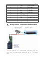
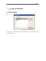
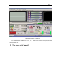
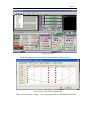
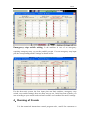
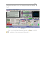
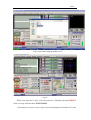
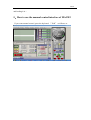
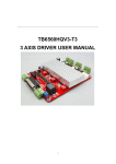
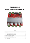
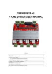
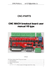
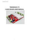
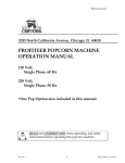
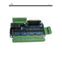
JSS
STEPS
STEPS
content
Ⅰ、Features: ..........................................................................................3
Ⅱ、Electrical drawing...............................................................................4
Ⅲ、limit switches and emergency stop switch connection methods: .......4
Ⅳ、Definition on pins of parallel port: ..................................................5
Ⅴ、Relay control port connection method ...............................................6
VI、Usage of MACH3...............................................................................7
1、Startup Mach3 ................................................................................7
3、Adjusting limits witch of mach3 ..................................................10
4、Running of G code ....................................................................... 11
5、How to use the manual control interface of MACH3 ..................14
STEPS
Ⅰ、Features:
1.full support for MACH3, KCAM4, EMC2, and support parallel
port to control the host computer software;
2.5 output signal ,can connect with 5 stepper motor driver ;
3.4 input port, Can connect to the limit switch, emergency stop,
or other Input devices ;
4.One relay, it can be used to control spindle start and stop;
5.Interface board built-in 5V power converter chip, can be
connected with DC 12V-60V power supply.
STEPS
Ⅱ、Electrical drawing
Power port:
Connect to
DC 12-60V
Power
Ⅲ 、 limit switches and emergency stop
switch connection methods:
Input interface, you can access limit, emergency stop switch can also
be connected to the reset, the knife and other input devices, when used
according to the actual situation of your set of reference the following
figure:
STEPS
Ⅳ、Definition on pins of parallel port:
25-pin parallel port control is defined as follows:
DB25 PIN
The role of the pin on
notes
driver board
1
EN
Enable of all axises
2
CKA
X pulse signal
3
CWA
X direction signal
4
CKB
Y pulse signal
5
CWB
Ydirection signal
6
CKC
Z pulse signal
7
CWC
Z direction signal
8
CKD
A pulse signal
STEPS
9
CWD
A direction signal
10
IN1
X axis Limit
11
IN2
Y axis Limit
12
IN3
Z axis Limit
13
IN4
A axis Limit
14
Relay control
15
IN4
Emergency stop
16
CKE
B(5th axis)pulse signal
17
CWE
B(5th axis)direction signal
18-25
GND
Ⅴ、Relay control port connection method
Note: Relay control port can be connected to the spindle motor, spindle motor
control
motor.
switch
or not to switch, the maximum can take 10A 277VAC spindle
STEPS
VI、Usage of MACH3
1、Startup Mach3
open mach3
When you have installed the software, here are 3 icons on the desk,let's click the
march3Mill, as fig 11.
STEPS
the main interface of march3
The main interface of MACH3 as fig 12 ,some basic buttons on it,Here, we first
configure MACH3.
2、The basic set of mach3
STEPS
set menu of mach3
Open the config menu, ports and pins menu, marked with red circlet
basic setting of direction and pulse pins
When you finished the setting,
click output signals then set ENABLE and Relay
STEPS
1 pin is the pin of control enabled, if the motor is not locked, you can switch the 1
pin's position, only the motor is locked ,when give pulsed to the driver ,it can
respond. 14 pin is a relay control pin, when the relay is not energized, the spindle also
need to be controlled by the following settings.
3、Adjusting limits witch of mach3
Click input signal,the parameter as follows
STEPS
Emergency stop switch setting: Is the machine in case of an emergency
requiring emergency stop, we put the parallel port pin 13 as an emergency stop input
pin, the corresponding mach3 settings as shown below:
For the three-axis system, the four input pins can limit switches, emergency stop
switch, reset switch settings, there are many ways to set, I only listed one of them, you
can according to your actual needs reference mach3 user's manual for mach3 settings.
4、Running of G code
G is the numerical instructions control program code , mach3 for customers to
STEPS
test software comes with the G code, you can easily test machine.click the File,as
fig 18
Fig 18 Open G
Click the red circlet Load G-code and open the icon
,and choice a G code, the interface as follows as fig 19
and click
STEPS
Fig 19 Open the testing procedures of G
Fig 20
When you open the G code, you may watch on a flashing red button RESET,
click it to stop, and click the CYCLESTART.
If you want to run your own G code for processing.find your location of G code,
STEPS
and leading it in.,
5、How to use the manual control interface of MACH3
If you want manual control, press the keyboard “TAB” as follows as :