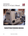
1
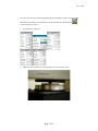
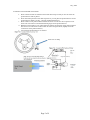
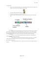
July ,2009
1.
Turn on screens and open Nanoscope SPM program from desktop. Click on warning to OK.
Select Real Time Mode by clicking this icon on the top left side of the menu bar:
You should see laser turn on.
a.
Set parameters in program.
b.
Make sure table is floating by checking that it is not contacting the legs.
Page 2 of 9
July ,2009
2. MOUNT CANTALEVER on the Holder
a.
b.
c.
d.
e.
Place cantilever holder on stand and focus under microscope so that you can see where the
probe/cantilever will be placed.
Press down clamp and move the metal clip back so you can place the probe/cantilever on the
probe/cantilever holder. See Fig. 7.3b from 3100D manual below.
Place cantilever into probe/cantilever holder and center it in the slot. Do not push it too far
back. This will result in an undesired mounting angle for the probe/cantilever.
Hold down clip and move over probe/cantilever making sure the body of the probe/cantilever
does not move. Come down on the location as shown on figure below (slightly left of the
vertical line on the probe/cantilever).
Verify that the probe/cantilever is centered.
Press here on clamp
Page 3 of 9
July ,2009
3. MOUNT CANTALEVER HOLDER: Do not drop the scanner! Piezo is very fragile.
a.
b.
c.
d.
Tighten scanning head screw on right side of scanning head.
Remove cantilever holder from stand and hold in your right hand keeping in mind how you
will have to place it on the scanning head.
Carefully lift the scanning head only touching the sides for the head and align the four pins
with the four holes in the cantilever holder.
Carefully press the cantilever holder onto the four pins. It only fits one way with the tip facing
towards the camera when the scanning head is mounted. Excessive force can destroy the
piezo also.
4. FIND TIP WITH LASER Do not drop the scanner! Piezo is very fragile.
a.
b.
While holding the scanning head adjust the knobs (laser aiming screws) on top of the head to
find the tip.
Sweep the top left knob back and forth to adjust the x-direction and find the edge where the
laser is blocked
Page 4 of 9
July ,2009
c.
d.
e.
f.
g.
When you find the edge where the laser is blocked move the bottom right knob, the ydirection, 1/20 of a turn clockwise, sweep in the x-direction again.
Repeat above two steps until you find a small shadow in the middle of the x-direction sweep.
This shadow is the cantilever tip.
If you have found the tip any slight change in the x-direction should cause the shadow to
disappear and the sum on the bottom of the right screen should disappear.
Maximize the sum with the x-direction knob
Turn the y-direction knob counterclockwise until the sum goes away and you are off the tip.
Then turn back clockwise and maximize the sum. Lastly reduce the sum to 95% by turning
the y-direction knob back counterclockwise.
5. REPLACE SCANNER HEAD
a. Carefully place the scanner head back into its slot on the microscope, making sure to not let
go until the head is below the line on the mounting bracket. Again a slight impact can shutter
the piezo.
b. Loosen scanning head screw until textured part of screw and plastic washer do not touch.
6. ADJUST PHOTODETECTER
a.
b.
Using knobs on side of scanner head (mirror adjusting screws) align the red dot to the center
of the detector box. The bottom knob moves in the x-direction and the top knob moves in the
y-direction
The vertical deflection should be within -.02 and .02 when the laser is properly aligned
Sum intensity from the photodetector
Page 5 of 9
July ,2009
7. LOCATE AND FOCUS TIP
a.
b.
c.
Press yellow focus tip button, and wait for the tip to stop moving in the vision system
window.
Using the ball hold down the focus button and focus the tip.
Using the knobs of the side of the camera place the crosshair on the tip slightly behind the
very end of the tip.
8. LOCATE AND FOCUS SURFACE
a.
b.
c.
d.
Place sample over vacuum chuck and turn on vacuum.
Make sure there is enough clearance between the sample and the cantilever holder by moving
the scanner head up with the red up arrow button.
Rotate the stage so the sample is under the scanning head
Press the red focus (and move) surface button
WARNING: As you focus down on the surface the scanning head is moving down. Do not allow the tip to
touch the surface. This could cause serious damage to the microscope which you will be responsible for.
e.
While holding the focus button on the ball and move the ball toward you. As things come into
focus let go of the focus button and move the ball so the stage moves, if the focused material
does not move with the track ball movement it is dust on the lens and you should continue to
focus moving the ball towards you until you find something that moves when you move the
stage.
TIP: if your sample is reflective or clear it may be a good idea to move to the edge of your slide and focus
on the top of the edge of the slide then move to where the sample is.
f.
Place crosshair on point of interest by moving this point by track ball while not holding focus
button.
9. TUNE THE TIP
Page 6 of 9
July ,2009
a.
b.
Press the tuning fork shaped button and the press AUTOTUNE
The sweep should look close to the picture below, and the curves should have that shape.
TIP: If you receive an error while tuning the tip is most likely not aligned correctly and you should go back
to step 4 and try again
10. TAKING AN IMAGE
Before approaching the surface, make sure the following:
1) Scan Size = 1μm.
2) Scan Rate = 2 Hz
3) Integral Gain = 0.5
4) Proportional Gain = 0.7
5) In addition, set X & Y Offsets = 0, Scan Angle = 0.
Scan Control & Feedback Control Panel
a.
Press the focus surface button again and move the crosshair to a point of interest and hit ok in
the focus surface window (if you have not done so already). When you are ready, click OK to
exit.
b.
Press the green approach surface button
then move the mouse over the abort button in
case something goes wrong. If something seems to not be right hit the abort button and try
again.
c.
Once the image begins to appear press the scope trace button.
Page 7 of 9
July ,2009
d.
e.
f.
g.
h.
i.
Select the amplitude setpoint and use the right arrow key to move the value up until the scope
trace lines are no longer together. This means the tip is no longer contacting the surface. (See
the Feedback Control Panel above)
Then using the left arrow key move the amplitude value down until the tip contacts the
surface again. Once the lines are tracking each other well move the amplitude setpoint value
down two more clicks by pressing the left arrow key twice.
Adjust integral gain. Increase this gain by right arrow key until you see the unstable noise sets
in.
Adjust proportional gain. (Usually this gain is 30-100% of the integral gain value.)
Press the eyeball button to go back to the image mode.
If you want to scan a larger area, lower the scan rate first, then increase the range. If you want
to scan smaller area, reduce the size first and increase the rate if needed. See the Training
Notebook for scan rate recommended for scan sizes. (Scan Control Panel)
TIP: If the scope will not align properly try adjusting the integral and proportional gain. As you move one
move the other the same amount. If you go one way and the scope gets worse try to go the other way.
11. CAPTURING IMAGE
Once you have a good image that you would like to save you must capture the image.
a.
b.
c.
Go to the “Capture” menu above the toolbar and select “Capture Filename.”
Change the capture filename to the name of your sample using the prompt that comes up and
select ok. A new number will be appended for each captured image on that sample, so there
will be no need to change the filename until you change samples.
Begin a scan from the bottom or top after adjusting your scan parameters to the desired
d.
settings.
Frame Up
Frame Down
The capture does not usually begin in the middle of the scan, but you can force the capture by
clicking the Capture (yellow camera) icon twice.
Click the yellow capture button shown on the toolbar.
12. ADJUSTING SCAN
a.
b.
c.
There are options at the top of the image viewing window typically displayed on the right
screen. These include “Zoom”, “Offset”, and “Execute”.
When you click “Zoom” your cursor will then become a moveable box which you can move
over an area of interest on the scan. A left-click will allow you to adjust the size of the box by
moving your mouse. A right click will then leave the box on the image, while allowing you
to use your cursor to hit the “Execute” button. This will change the scan size and position so
that only the area in the box is now being scanned. Remember to reduce the scan rate if you
are going to a larger scan area.
When you click “Offset” your cursor will become crosshairs that you can move over the
image, and finalize the position of with a right-click. When you hit “Execute” the image
parameters will remain the same, but the image will be centered at the point designated by the
crosshairs.
13. When you are done correcting images at this location, click Disengage icon
. To move to a new
location, you must open the Locate Surface icon again. Remember you must re-approach with 1
micron/2Hz if you replace the sample.
Page 8 of 9
July ,2009
14. ANALYSIS
a.
Once you have captured the image you go to the image file handler to look at the image. This
button is on the top right of the window on the left screen.
Can return to Real Time mode by this icon.
b.
c.
First select the image that you would like to analyze.
Then go to Image->Select Left Image. This will choose the image that is the actual height
data.
FLATTEN
Flatten will give you the image that you first saw when you scanned. This is necessary to
get an accurate representation of the surface. Do this before any other analysis. You will get a warning
that you are about to modify the data. Click ok and you will NOT SAVE at the end. Tip: You can draw
rectangles to exclude some regions from this routine. This is often improves the flattened images.
3D IMAGE
This gives you a three dimensional representation of the surface. This will help you
interpret some data.
CROSS-SECTIONAL ANALYSIS
This will allow you to measure the dimensions of features on the surface. You start by
making a line across the image then use the two cursers to measure the topography along that line.
ROUGHNESS ANALYSIS
Tells you how rough the surface is. This gives a measurement of the deflection in the Zdirection.
Page 9 of 9