1
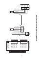
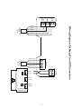
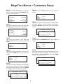
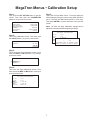
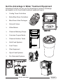
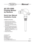
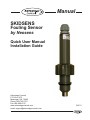
Manual SKIDSENS Fouling Sensor by Neosens Quick User Manual Installation Guide Advantage Controls P.O. Box 1472 Muskogee, OK 74402 Phone: 800-743-7431 Fax: 888-686-6212 www.advantagecontrols.com email: [email protected] 4/2011 Specifications Electrical: • Input: 36 VDC @ 60mA • Output: 4-20mA (500 Ω) Environment: • Ambient temperature - 0 to 180oF (without PVC adapter) • Relative humidity - 0 to 100% • Pressure - 80 PSI Max Fouling Monitoring: 0-1 mm (0 to 0.039 in) Accuracy:1% of Full scale Material: PVC (body) & 316L SS (sensor tip) Connection: • Sensors are supplied with a 1” (2.54 cm) slip and a 1” MNPT PVC quick release adaptor. The PVC adaptor has a maximum temperature rating of 125oF. • Peak sensor body has 1/2” straight BMPT Shipping Weight: 4 lbs (1.814 kg) Sensor Length: Insertion Depth: 9.375” (23.8 cm) Approx. 3.375” (8.57 cm) Installation Notes 1. Install the sensor into flowing water for 30 minutes to allow the sensor to reach a temperature equilibrium. 2. Sensor must have a minimum of 3.5 gpm flow across it. 3. The analog output is active and referenced to +36Vdc. 4. If connected to a monitor with other 4-20mA inputs, they must be isolated from each other or this input. Contact Advantage Controls if a loop isolator is required. 5. After the sensor has been installed and powered for 2 hours confirm that the output is a 4mA signal. Testing Sensor If the sensor is giving a 3mA output after being installed for at least 2 hours in the minimum flow rate of 3.5 gpm the following steps can be followed to test and reset the sensor’s operation. 1. Power OFF the Skidsens 2. Assuming the Skidsens was maintained in water with the required flow rate (>3.5gpm), power ON the Skidsens and check the analog output reading during the first 20 seconds, as the probe will be in test mode a. For the first 10 seconds, the probe should display a 4mA signal b. For the next 10 seconds, the probe should display a 20mA signal 3. After those initial 20 seconds, the probe will go to operational mode and should return to a 4mA signal, or slightly above assuming the sensor has no fouling. Sensor Input Power GREEN (GND) 4-20mA Probe Out + -- J1-1 J1-8 J2-1 J2-8 Wiring Diagram for MegaTron Connection BLACK (HOT) Power Cord LED 4-20mA Input Card 4-20mA Input 84-20mA Input 8+ 4-20mA Input 74-20mA Input 7+ 4-20mA Input 64-20mA Input 6+ 4-20mA Input 54-20mA Input 5+ 4-20mA Input 44-20mA Input 4+ 4-20mA Input 34-20mA Input 3+ 4-20mA Input 24-20mA Input 2+ 4-20mA Input 14-20mA Input 1+ Note: The number of channels or 4-20mA inputs depends on on the number ordered. GND -+ -+ BLUE BROWN BLACK WHITE SKIDSENS Probe WHITE (NEU) Signal 36 VDC YELLOW -+ -+ Sensor Input GND Signal 36 VDC SKIDSENS Probe BLUE BROWN WHITE BLACK BLACK (HOT) Power Power Cord WHITE (NEU) GREEN (GND) + -- Input 1 Input 1 + Input 2 Input 2 + Rev D Input 3 Input 3 + MegaTron SS 4-20mA Input 4-20mA Probe Out Part # SS-MAI-2 Wiring Diagram for MegaTron SS Connection YELLOW MegaTron Menus • Customize Setup Step 1: Step 6: First, push the SET UP RUN button to get this screen. From here push the CUSTOMIZE (Button 4) to go to the next screen. From here push the UNITS (Button 2) to go to the next screen. >CUSTOMIZE mA INPUT 1< >HOME SETUP< SETPOINTS CALIBRATION TIMERS CUSTOMIZE ALARMS DATE/TIME CONFIGURE HISTORY WATER METER RELAYS NAME FOULING UNITS NUMBER mm x.xxx Step 7: This is the Customize mA Units screen. From here select the type of units (i.e. mm) by using the Arrow buttons. Then press ENTER to confirm and return to the previous screen. Step 2: This is the Customize Screen. From here push the mA IN (Button 9) to go to the next screen. >CUSTOMIZE< >CUSTOMIZE mA INPUT 1< UNIT NAME RELAY NAMES SYS NAME INPUT NAMES NAME FOULING TYPE OFmm UNITS UNITS NOTEPAD NUMBER mA IN x.xxx -> mm USE UP/DOWN KEYS TO CHANGE PRESS ENTER TO ACCEPT RUN SCREEN Step 3: Step 8: This is the mA IN screen. From here push INPUT 1 OR 2 (Button 1 or 2) then go to the next screen. From here push the NUMBER (Button 3) to go to the next screen. >CUSTOMIZE mA INPUT 1< >CUSTOMIZE mA INPUTS< INPUT 1 INPUT 2 NAME FOULING UNITS NUMBER mm x.xxx Step 9: Step 4: This is the Customize mA Number Format screen. From here select the number format (i.e. x.xxx) by using the Arrow buttons. Then press ENTER to confirm and HOME to return to the Home screen. This is the Customize mA Input 1 Screen. From here push the NAME (Button 1) to go to the next screen. >CUSTOMIZE mA INPUT 1< NAME FOULING UNITS NUMBER mm x.xxx >CUSTOMIZE mA INPUT 1< NAME FOULING NUMBER mm FORMAT UNITS NUMBER x.xxx-> X.XXX USE UP/DOWN KEYS TO CHANGE PRESS ENTER TO ACCEPT Step 5: This is the Customize mA Name screen. From here enter the name of the mA Input (i.e. FOULING) by using the Arrow buttons. Then press ENTER to confirm and return to the previous screen. >CUSTOMIZE mA INPUT 1< NAME FOULING mA INPUT UNITS mm1 NAME NUMBER x.xxx [FOULING ] USE ARROW KEYS TO CHANGE, PRESS ENTER TO ACCEPT OR BACK TO ERASE MegaTron Menus • Calibration Setup Step 1: First, push the SET UP RUN button to get this screen. From here push the CALIBRATION (Button 2) to go to the next screen. >HOME SETUP< SETPOINTS CALIBRATION TIMERS CUSTOMIZE ALARMS DATE/TIME CONFIGURE HISTORY WATER METER RELAYS Step 5: This is the mA Input MAX screen. From here adjust the MAX reading by using the number keys (MAX should be set to 1.000 mm and MIN should be set to 0.000 mm). Then press ENTER to confirm and return to the previous screen. Note: All other mA Input Calibration settings can be adjusted in the same fashion beginning at Step 4. >mA INPUT CALIBRATION< Step 2: 20 mA This is the Calibration Screen. From here push the mA IN (Button 7) to go to the next screen. >CALIBRATION< SENSORS USE NUMBER KEYS TO CHANGE, PRESS ENTER TO ACCEPT OR BACK TO ERASE mA OUT mA IN Step 3: This is the Curren Loop Calibration screen. From here push INPUT 1 OR 2 (Button 1 or 2) then go to the next screen. >CURRENT LOOP CALIBRATION< INPUT 1 INPUT 2 Step 4: This is the mA Input Calibration Screen. From here choose the MAX or MIN (Button 3 and 4) to go to the next screen. >mA INPUT CALIBRATION< 20 mA 19649 4 mA MAX MIN OFFSET 3913 1.000 mm 0.000 mm Enabled 19649 4 mA 3913 MAX 1.000 mm 1 MAX MINmA INPUT 0.000 mm(1.000 mm) [_. ] mm OFFSET Enabled Get the Advantage in Water Treatment Equipment Advantage Controls can give you the Advantage in products, knowledge and support on all of your water treatment equipment needs. Cooling Tower Controllers Boiler Blow Down Controllers Blow Down Valve Packages Solenoid Valves Water Meters Chemical Metering Pumps Corrosion Coupon Racks Chemical Solution Tanks Solid Feed Systems Feed Timers Filter Equipment Glycol Feed Systems Pre Fabricated Systems Get the Advantage