1
JSP for LatticeMico32 User Manual
Version 1.6
March, 2008
1
Table of Contents
TABLE OF CONTENTS .............................................................................................. 2
1
OVERVIEW........................................................................................................... 3
2
SYSTEM FUNCTIONS......................................................................................... 3
2.1
2.2
2.3
2.4
2.5
2.6
2.7
2.8
2.9
2.10
2.11
3
TASK MANAGEMENT FUNCTIONS ..................................................................... 3
TASK DEPENDENT SYNCHRONIZATION FUNCTIONS .......................................... 3
TASK EXCEPTION HANDLING FUNCTIONS ......................................................... 4
SYNCHRONIZATION AND COMMUNICATION FUNCTIONS ................................... 4
EXTENDED SYNCHRONIZATION AND COMMUNICATION FUNCTIONS ................. 5
MEMORY POOL MANAGEMENT FUNCTIONS...................................................... 6
TIME MANAGEMENT FUNCTIONS ...................................................................... 6
SYSTEM STATE MANAGEMENT FUNCTIONS ...................................................... 7
INTERRUPT MANAGEMENT FUNCTIONS ............................................................ 7
SERVICE CALL MANAGEMENT FUNCTIONS ....................................................... 7
SYSTEM CONFIGURATION MANAGEMENT FUNCTIONS ...................................... 7
BUILDING THE DEVELOPMENT ENVIRONMENT.................................... 8
3.1
THE HARDWARE PLATFORM ............................................................................. 8
3.1.1
The HOST................................................................................................. 8
3.1.2
The TARGET............................................................................................ 8
3.2
THE SOFTWARE ENVIRONMENT ........................................................................ 9
4
HOW TO PROGRAM, BUILD AND DEBUG APPLICATIONS.................... 9
4.1
4.2
4.3
5
PROGRAM APPLICATIONS ................................................................................. 9
BUILD APPLICATIONS ..................................................................................... 11
DEBUG APPLICATIONS .................................................................................... 11
ADVANCED ISSUES.......................................................................................... 12
5.1
CONFIGURATION ON DIFFERENT PLATFORMS ................................................. 12
5.2
INSTALLING THE EXCEPTION HANDLER AND INTERRUPT HANDLER ............... 13
5.2.1
Installing the Exception Handler ........................................................... 13
5.2.2
Installing the Interrupt Handler............................................................. 14
5.2.3
Boot ........................................................................................................ 15
6
APPENDIX........................................................................................................... 18
6.1
6.2
6.3
6.4
TESTED BOARDS LIST ..................................................................................... 18
EXAMPLE PLATFORM MAP ............................................................................. 18
INITIALIZING THE MEMORY COMPONENT ....................................................... 18
HOW TO PROGRAM THE OS IMAGE (JSP.BIN) AND THE BOOT-LOADER IMAGE
BOOT.BIN TO THE FLASH.............................................................................................. 18
6.5
LINK FILE FOR STORE AND RUN THE IMAGE IN THE INTERNAL MEMORY ......... 20
6.6
LINK FILE FOR STORE THE IMAGE IN FLASH AND RUN IN THE SRAM ................. 23
March, 2008
2
1 Overview
The user manual describes how to develop applications on the JSP kernel for the
LatticeMico32. The TOPPERS/JSP is a royalty-free, open source embedded realtime operation system, developed by the TOPPERS Project. JSP is an acronym for
Just Standard Profile, and as the name shows, is implemented in accordance with
the µITRON4.0 specification standard profile regulation. The LatticeMico32™ is a
configurable 32-bit soft processor core for Lattice Field Programmable Gate Array
(FPGA) devices. By combining a 32-bit wide instruction set with 32 general
purpose registers, the LatticeMico32 provides the performance and flexibility
suitable for a wide variety of markets, including communications, consumer,
computer, medical, industrial, and automotive. With separate instruction and data
buses, this Harvard architecture processor allows for single-cycle instruction
execution as the instruction and data memories can be accessed simultaneously.
Additionally, the LatticeMico32 uses a Reduced Instruction Set Computer (RISC)
architecture; thereby, providing a simpler instruction set and faster performance.
This manual is targeted to the software programmers who are interested in
developing JSP applications for the LatticeMico32.
2 System Functions
The JSP system functions are listed in the following tables1. And C library is not be
implemented.
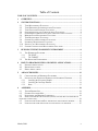
2.1 Task Management Functions
Name
CRE_TSK
cre_tsk
acre_tsk
del_tsk
act_tsk
iact_tsk
can_act
sta_tsk
ext_tsk
exd_tsk
ter_tsk
chg_pri
get_pri
ref_tsk
ref_tst
Description
Create Task
Create Task
Create Task (ID Number Automatic
Assignment)
Delete Task
Activate Task
Activate Task
Cancel Task Activation Requests
Activate Task (with a Start Code)
Terminate Invoking Task
Terminate and Delete Invoking Task
Terminate Task
Change Task Priority
Reference Task Priority
Reference Task State
Reference Task State (Simplified Version)
API
Static
C Language
C Language
Implemented
Yes
No
No
C Language
C Language
C Language
C Language
C Language
C Language
C Language
C Language
C Language
C Language
C Language
C Language
No
Yes
Yes
Yes
No
Yes
No
Yes
Yes
Yes
No
No
2.2 Task Dependent Synchronization Functions
Name
slp_tsk
tslp_tsk
wup_tsk
iwup_tsk
Description
Put Task to Sleep
Put Task to Sleep (with Timeout)
Wakeup Task
Wakeup Task
API
C Language
C Language
C Language
C Language
Implemented
Yes
Yes
Yes
Yes
1
For details on system functions, refer to the “uITRON4.0 Specification”. In the JSP, the functions
defined in the “uITRON4.0 Specification” are implemented.)
March, 2008
3
can_wup
rel_wai
irel_wai
sus_tsk
rsm_tsk
frsm_tsk
dly_tsk
Cancel Task Wakeup Requests
Release Task from Waiting
Release Task from Waiting
Suspend Task
Resume Suspended Task
Forcibly Resume Suspended Task
Delay Task
C Language
C Language
C Language
C Language
C Language
C Language
C Language
Yes
Yes
Yes
Yes
Yes
Yes
Yes
API
Static
C Language
C Language
C Language
C Language
C Language
C Language
C Language
Implemented
Yes
No
Yes
Yes
Yes
Yes
Yes
No
2.3 Task Exception Handling Functions
Name
DEF_TEX
def_tex
ras_tex
iras_tex
dis_tex
ena_tex
sns_tex
ref_tex
Description
Define Task Exception Handling Routine
Define Task Exception Handling Routine
Raise Task Exception Handling
Raise Task Exception Handling
Disable Task Exceptions
Enable Task Exceptions
Reference Task Exception Handling State
Reference Task Exception Handling State
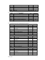
2.4 Synchronization and Communication Functions
Name
CRE_SEM
cre_sem
acre_sem
del_sem
sig_sem
isig_sem
wai_sem
pol_sem
twai_sem
ref_sem
Name
CRE_FLG
cre_flg
acre_flg
del_flg
set_flg
iset_flg
clr_flg
wai_flg
pol_flg
twai_flg
ref_flg
Name
CRE_DTQ
cre_dtq
acre_dtq
del_dtq
snd_dtq
psnd_dtq
March, 2008
Semaphores
Description
Create Semaphore
Create Semaphore
Create Semaphore (ID Number Automatic
Assignment)
Delete Semaphore
Release Semaphore Resource
Release Semaphore Resource
Acquire Semaphore Resource
Acquire Semaphore Resource (Polling)
Acquire Semaphore Resource (with Timeout)
Reference Semaphore State
Eventflags
Description
Create Eventflag
Create Eventflag
Create Eventflag (ID Number Automatic
Assignment)
Delete Eventflag
Set Eventflag
Set Eventflag
Clear Eventflag
Wait for Eventflag
Wait for Eventflag (Polling)
Wait for Eventflag (with Timeout)
Reference Eventflag Status
Data Queues
Description
Create Data Queue
Create Data Queue
Create Data Queue (ID Number Automatic
Assignment)
Delete Data Queue
Send to Data Queue
Send to Data Queue (Polling)
API
Static
C Language
C Language
Implemented
Yes
No
No
C Language
C Language
C Language
C Language
C Language
C Language
C Language
No
Yes
Yes
Yes
Yes
Yes
No
API
Static
C Language
C Language
Implemented
Yes
No
No
C Language
C Language
C Language
C Language
C Language
C Language
C Language
C Language
No
Yes
Yes
Yes
Yes
Yes
Yes
No
API
Static
C Language
C Language
Implemented
Yes
No
No
C Language
C Language
C Language
No
Yes
Yes
4
ipsnd_dtq
tsnd_dtq
fsnd_dtq
ifsnd_dtq
rcv_dtq
prcv_dtq
trcv_dtq
ref_dtq
Name
CRE_MBX
cre_mbx
acre_mbx
del_mbx
snd_mbx
rcv_mbx
prcv_mbx
trcv_mbx
ref_mbx
Send to Data Queue (Polling)
Send to Data Queue (with Timeout)
Forced Send to Data Queue
Forced Send to Data Queue
Receive from Data Queue
Receive from Data Queue (Polling)
Receive from Data Queue (with Timeout)
Reference Data Queue State
Mailboxes
Description
Create Mailbox
Create Mailbox
Create Mailbox (ID Number Automatic
Assignment)
Delete Mailbox
Send to Mailbox
Receive from Mailbox
Receive from Mailbox (Polling)
Receive from Mailbox (with Timeout)
Reference Mailbox State
C Language
C Language
C Language
C Language
C Language
C Language
C Language
C Language
Yes
Yes
Yes
Yes
Yes
Yes
Yes
No
API
Static
C Language
C Language
Implemented
Yes
No
No
C Language
C Language
C Language
C Language
C Language
C Language
No
Yes
Yes
Yes
Yes
No
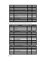
2.5 Extended Synchronization and Communication Functions
Name
CRE_MTX
cre_mtx
acre_mtx
del_mtx
loc_mtx
ploc_mtx
tloc_mtx
unl_mtx
ref_mtx
Name
CRE_MBF
cre_mbf
acre_mbf
del_mbf
snd_mbf
psnd_mbf
tsnd_mbf
rcv_mbf
prcv_mbf
trcv_mbf
ref_mbf
Name
CRE_POR
cre_por
acre_por
del_por
cal_por
tcal_por
March, 2008
Mutexes
Description
Create Mutex
Create Mutex
Create Mutex (ID Number Automatic
Assignment)
Delete Mutex
Lock Mutex
Lock Mutex (Polling)
Lock Mutex (with Timeout)
Unlock Mutex
Reference Mutex State
Message Buffers
Description
Create Message Buffer
Create Message Buffer
Create Message Buffer (ID Number
Automatic Assignment)
Delete Message Buffer
Send to Message Buffer
Send to Message Buffer (Polling)
Send to Message Buffer (with Timeout)
Receive from Message Buffer
Receive from Message Buffer (Polling)
Receive from Message Buffer (with Timeout)
Reference Message Buffer State
Rendezvous
Description
Create Rendezvous Port
Create Rendezvous Port
Create Rendezvous Port (ID Number
Automatic Assignment)
Delete Rendezvous Port
Call Rendezvous Port
Call Rendezvous Port (with Timeout)
API
Static
C Language
C Language
Implemented
No
No
No
C Language
C Language
C Language
C Language
C Language
C Language
No
No
No
No
No
No
API
Static
C Language
C Language
Implemented
No
No
No
C Language
C Language
C Language
C Language
C Language
C Language
C Language
C Language
No
No
No
No
No
No
No
No
API
Static
C Language
C Language
Implemented
No
No
No
C Language
C Language
C Language
No
No
No
5
acp_por
pacp_por
tacp_por
fwd_por
rpl_rdv
ref_por
ref_rdv
Accept Rendezvous
Accept Rendezvous (Polling)
Accept Rendezvous (with Timeout)
Forward Rendezvous
Terminate Rendezvous
Reference Rendezvous Port State
Reference Rendezvous State
C Language
C Language
C Language
C Language
C Language
C Language
C Language
No
No
No
No
No
No
No
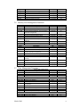
2.6 Memory Pool Management Functions
Name
CRE_MPF
cre_mpf
acre_mpf
del_mpf
get_mpf
pget_mpf
tget_mpf
rel_mpf
ref_mpf
Name
CRE_MPL
cre_mpl
acre_mpl
del_mpl
get_mpl
pget_mpl
tget_mpl
rel_mpl
ref_mpl
Fixed-Sized Memory Pools
Description
Create Fixed-Sized Memory Pool
Create Fixed-Sized Memory Pool
Create Fixed-Sized Memory Pool (ID Number
Automatic Assignment)
Delete Fixed-Sized Memory Pool
Acquire Fixed-Sized Memory Block
Acquire Fixed-Sized Memory Block (Polling)
Acquire Fixed-Sized Memory Block (with
Timeout)
Release Fixed-Sized Memory Block
Reference Fixed-Sized Memory Pool State
Variable-Sized Memory Pools
Description
Create Variable-Sized Memory Pool
Create Variable-Sized Memory Pool
Create Variable-Sized Memory Pool (ID
Number Automatic Assignment)
Delete Variable-Sized Memory Pool
Acquire Variable-Sized Memory Block
Acquire Variable-Sized Memory Block
(Polling)
Acquire Variable-Sized Memory Block (with
Polling)
Release Variable-Sized Memory Block
Reference Variable-Sized Memory Pool State
API
Static
C Language
C Language
Implemented
Yes
No
No
C Language
C Language
C Language
C Language
No
Yes
Yes
Yes
C Language
C Language
Yes
No
API
Static
C Language
C Language
Implemented
No
No
No
C Language
C Language
C Language
No
No
No
C Language
No
C Language
C Language
No
No
API
C Language
C Language
C Language
Implemented
Yes
Yes
Yes
API
Static
C Language
C Language
Implemented
Yes
No
No
C Language
C Language
C Language
C Language
No
Yes
Yes
No
API
Static
Implemented
No
2.7 Time Management Functions
Name
set_tim
get_tim
isig_tim
Name
CRE_CYC
cre_cyc
acre_cyc
del_cyc
sta_cyc
stp_cyc
ref_cyc
Name
CRE_ALM
March, 2008
System Time Management
Description
Set System Time
Reference System Time
Supply Time Tick
Cyclic Handlers
Description
Create Cyclic Handler
Create Cyclic Handler
Create Cyclic Handler (ID Number Automatic
Assignment)
Delete Cyclic Handler
Start Cyclic Handler Operation
Stop Cyclic Handler Operation
Reference Cyclic Handler Operation
Alarm Handlers
Description
Create Alarm Handler
6
cre_alm
acre_alm
del_alm
sta_alm
stp_alm
ref_alm
Name
DEF_OVR
def_ovr
sta_ovr
stp_ovr
ref_ovr
Create Alarm Handler
Create Alarm Handler (ID Number Automatic
Assignment)
Delete Alarm Handler
Start Alarm Handler Operation
Stop Alarm Handler Operation
Reference Alarm Handler State
Overrun Handlers
Description
Define Overrun Handler
Define Overrun Handler
Start Overrun Handler Operation
Stop Overrun Handler Operation
Reference Overrun Handler State
C Language
C Language
No
No
C Language
C Language
C Language
C Language
No
No
No
No
API
Static
C Language
C Language
C Language
C Language
Implemented
No
No
No
No
No
API
C Language
C Language
C Language
C Language
C Language
C Language
C Language
C Language
C Language
C Language
C Language
C Language
C Language
C Language
C Language
Implemented
Yes
Yes
Yes
Yes
Yes
Yes
Yes
Yes
Yes
Yes
Yes
Yes
Yes
Yes
No
API
Static
C Language
Static
C Language
C Language
Implemented
Yes
No
No
No
No
C Language
C Language
C Language
C Language
C Language
C Language
No
No
Yes
Yes
No
No
API
Static
C Language
C Language
Implemented
No
No
No
2.8 System State Management Functions
Name
rot_rdq
irot_rdq
get_tid
iget_tid
loc_cpu
iloc_cpu
unl_cpu
iunl_cpu
dis_dsp
ena_dsp
sns_ctx
sns_loc
sns_dsp
sns_dpn
ref_sys
Description
Rotate Task Precedence
Rotate Task Precedence
Reference Task ID in the RUNNING State
Reference Task ID in the RUNNING State
Lock the CPU
Lock the CPU
Unlock the CPU
Unlock the CPU
Disable Dispatching
Enable Dispatching
Reference Contexts
Reference CPU State
Reference Dispatching State
Reference Dispatching Pending State
Reference System State
2.9 Interrupt Management Functions
Name
DEF_INH
def_inh
ATT_ISR
cre_isr
acre_isr
del_isr
ref_isr
dis_int
ena_int
chg_ixx
get_ixx
Description
Define Interrupt Handler
Define Interrupt Handler
Attach Interrupt Service Routine
Create Interrupt Service Routine
Create Interrupt Service Routine (ID Number
Automatic Assignment)
Delete Interrupt Service Routine
Reference Interrupt Service Routine State
Disable Interrupt
Enable Interrupt
Change Interrupt Mask
Reference Interrupt Mask
2.10 Service Call Management Functions
Name
DEF_SVC
def_svc
cal_svc
Description
Define Extended Service Call
Define Extended Service Call
Invoke Service Call
2.11 System Configuration Management Functions
Name
March, 2008
Description
API
Implemented
7
DEF_EXC
def_exc
ref_cfg
ref_ver
ATT_INI
Define CPU Exception Handler
Define CPU Exception Handler
Reference Configuration Information
Reference Version Information
Attach Initialization Routine
Static
C Language
C Language
C Language
Static
Yes
No
No
No
Yes
3 Building the Development Environment
3.1 The Hardware Platform
Before you can build applications, the hardware platform must be established.
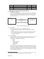
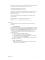
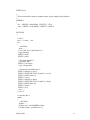
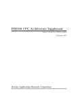
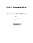
In general, the embedded hardware platform composes of two parts: the HOST
and the TARGET. The following diagram illustrates the basic composition of
the hardware platform.
[Y.F. Zhao1]
RS232
PC
Target Board
JTAG
HOST
TARGET
Figure1: System development platform
3.1.1 The HOST
Here are the steps that needs to be accomplished on the host:
1. Build the JSP kernel image for the target LatticeMico32 Development
Board.
2. Download the JSP kernel image to the target board through the JTAG port.
3. Observe that the debug information are displayed on the target board
through the UART port.
3.1.2 The TARGET
On the target side, run the image. Send the information to the host or receive the
input from the host through the UART port. Make sure that the following
components are included in the target board:
Timer
UART
Storage Component:
Internal RAM
External SRAM
FLASH
There are two possible configurations of the storage component. If the internal
RAM is large enough to accommodate the kernel image, the storage component
will be the internal RAM only. Otherwise the image must be stored in the flash
and run in an external SRAM. In this case, the storage component must include
the external SRAM and the flash.2
.
2
For more details on how to build the platform, refer to “LatticeMico32 Development Kit User’s Guide
for LatticeECP” and “LatticeMico32 Development Kit User’s Guide for LatticeECP2”.
March, 2008
8
3.2 The Software Environment
Before you can build applications, the software environment must be ready. Here is
a checklist for you to check the readiness of your software environment:
1. The LatticeMico32 Development Tools are installed.
2. The JSP source code and the hardware-dependence code for LatticeMico32 are
available3
3. The hardware-dependent code for LatticeMico32 is placed in the directory
“jsp\config”.
4. The C compiler is installed. It can be one among the following three:
Microsoft Visual C++ 6.0
GCC
BCC
5. The configurator is built. If not, follow the next steps to build the configurator:
If the Microsoft Visual C++ 6.0 is installed
1. Enter the directory “jsp\cfg\ vc_project”.
2. Open the file “configurator.dsw” with the Microsoft Visual C++ 6.0.
3. Click the menu command “build” and select the option “Batch Build…”.
4. Select all projects to be built. When completd, the file “cfg.exe” is generated
in the directory “jsp/cfg”.
If the GCC is installed
1. Enter the directory “jsp\cfg”
2. Run the file “Makefile”
If the BCC is installed
1. Enter the directory “jsp\cfg”
2. Run the file “Makefile.bcc”
4 How to Program, Build and Debug Applications
4.1 Program Applications
The Application source code composes of two parts:
1. The configuration file (*.cfg)
2. The C file (*.c) and the include file(*.h).
The file names of the C file and the configuration file must be the same.
In the configuration file, the function can only be invoked with “API” that is
marked “Static” in the function tables introduced in the previous sections.
Configuration information is usually defined in the file and includes the
following sections:
Task ID
Task Attribute
Task Start address
Task Initial Priority
Task Stack Size
Exception Handler
Interrupt Handler
3
The JSP source code can be downloaded from the TOPPERS/JSP official web
http://www.toppers.jp/en/index.html.
March, 2008
9
In the C file, you can write the main body of those tasks that are defined in the
configuration file.
The macro used for the configuration file is defined in the include file.
Also the function definition about the task must be included in the include file.
Insert the definition of the task function between the line “#ifndef
_MACRO_ONLY” and the line “#endif” in the include file.
The following example helps you understand it better. The example, when
implemented, prints the string “Hello World!!!” to the UART every 2 seconds4.
To implement the example, follow these steps:
Step 1: Create a configuration file with the name “hello_world.cfg”. Copy the
following content into the configuration file:
/*-----------------------------hello_world.cfg-----------------------*/
#define _MACRO_ONLY
#include "hello_world.h"
INCLUDE("\"hello_world.h\"");
CRE_TSK(TASK_ID, { TA_HLNG|TA_ACT, NULL, hello_world_task, TASK_PRIORITY,
STACK_SIZE, NULL });
#include "./systask/timer.cfg"
#include "./systask/serial.cfg"
/*-------------------------------------------------------------------*/
Step 2: Create the file “hello_world.c” and copy the following content into the file.
This file defines the main body of the task. :
/*---------------------------hello_world.c---------------------------*/
#include <t_services.h>
#include "../../kernel/jsp_kernel.h"
void hello_world_task (VP_INT exinf)
{
for(;;)
{
syslog_printf("Hello World!!!\n", NULL, sys_putc);
_syscall(dly_tsk(2));
}
}
/*-------------------------------------------------------------------*/
Step 3: Create the file “hello_world.h” and copy the following content into the
file.
/*---------------------------hello_world.h---------------------------*/
#ifndef __HELLO_WORLD_H__
#define __HELLO_WORLD_H__
#include <t_services.h>
#define
#define
TASK_PRIORITY 5
STACK_SIZE
512
#ifndef _MACRO_ONLY
extern void
hello_world_task(VP_INT exinf);
4
The macro “TASK_ID” does not need to be defined. It will be generated automatically in the build
process. The macro “TA_HLNG” is defined in the file “\jsp\include\kernel.h”. Refer to the “uITRON4.0
Specification” for more information about the task macro definition.
March, 2008
10
#endif
#endif
/*-------------------------------------------------------------------*/
4.2 Build Applications
Before build, the link file “config\lm32\ECP2\lm32elf.ld” should be ready,
it decided by the image storage format. Appendix6.5 and 6.6 lists two
kinds of link file for the “hello_world” example, the following steps show
you how to build applications.
Step 1: Copy the C file, include file and the configuration file to the destination
directory. The destination directory can be set as the “jsp” or the subdirectory
under the “jsp”, such as “jsp/test”.
Step 2: Open the LatticeMico32 System Shell and enter the destination directory
in the shell.
Step 3: Run the following command in the shell:
if the destination directory is “jsp”,
-------------------------------------
Command: ./configure -C lm32 -S ECP2 -A hello_world
-------------------------------------
if the destination directory is “jsp/test”
The related directory in the application code should be modfied accordingly.
-------------------------------------
Command: ../configure –C lm32 –S ECP2 –A hello_world.
-------------------------------------
Step 4: Run the following command in the shell:
-------------------------------------
make depend
-------------------------------------
Five files (kernel_id.h, kernel_cfg.c,kernel_chk.c, Makefile.depend and offset.h)
will be generated.
Step 5: Run the following command in the shell:
-------------------------------------
make; make jsp.bin
-------------------------------------
This step generates the file “jsp.exe” and “jsp.bin”
If some modification was made to the application code, please go to run Step 4
and Step5.
4.3 Debug Applications
The following steps show you how to debug applications:
Step 1: Open the LatticeMico32 System shell and type the following command in
the shell
the shell:
-------------------------------------
TCP2JTAGVC2
-------------------------------------
Step 2: Open another LatticeMico32 System shell and enter the destination
directory, type the following command to enter the GDB debug
environment:
-------------------------------------
lm32-elf-gdb jsp.exe
-------------------------------------
Step 3: Enter the GDB debug environment and link to the target board by
entering the following command in the GDB debug environment:
March, 2008
11
-------------------------------------
target remote localhost:1000
-------------------------------------
Step 4: Load the image to the target board by entering the following command
in the GDB debug environment:
-------------------------------------
load
-------------------------------------
Step 5: The application can be debugged now. Refer to the GDB User Manual
for details of the GDB usage.
5 Advanced Issues
5.1 Configuration on Different Platforms
Because the SOC (System on Chip) can be modified, the platform may
accordingly have different configurations. Here is a list of possible different
configurations:
1. The clock of the target CPU is variable.
2. The target board UART baud rate used to communicate with the PC is
different from the default.
3. The UART registers start address or Timer registers start address of the target
board is different from the default.
4. The target board SRAM start address or size is different from the default.
The configuration of the target board can be found in the header file
“jsp\config\lm32\ECP2\lm32.h”. Here is an example of the header file:
/*------------------------- lm32.h ---------------------------*/
……
#define MICO32_CPU_CLOCK_HZ
(25000000)
#define DEFAULT_UART_BAUDRATE
(115200)
#define TIMER_BASE_REG
(0x80000100)
#define UART1_BASE_REG
(0x80000180)
……
/*------------------------- lm32.h ---------------------------*/
When the following configuration of the target board is different from the default,
you can modify the corresponding definition in the file “lm32.h”:
CPU Clock
UART Baud rate
UART Registers Start Address
Timer Registers Start Address
If the SRAM start address or size needs to be modified, you can edit the link file
“jsp\config\lm32\ ECP2\lm32elf.ld”. Here is an example of the link file:
/*--------------------- lm32elf.ld --------------------------*/
……
MEMORY
{
sram : ORIGIN = 0x00100000, LENGTH = 131072
}
……
/*-----------------------------------------------------------*/
March, 2008
12
ORIGIN =
Length =
XXXXXXXX
YYYYYYYY
0xXXXXXXXX
YYYYYYYY
: The SRAM Start Address
: The SRAM Size
5.2 Installing the Exception Handler and Interrupt Handler
5.2.1 Installing the Exception Handler
In the JSP, there are two types of exception handlers:
1. System exception handler
2. Task exception handler
The following diagram lists the system exceptions in the LatticeMico32
Exception
Reset
Breakpoint
ID
0
1
InstructionBusError
2
Watchpoint
DataBusError
3
4
DivideByZero
Interrupt
5
6
SystemCall
7
Condition
Raised when the processor’s reset pin is asserted.
Raised when either a break instruction is executed or when a
hardware breakpoint is triggered.
Raised when an instruction fetch fails, typically due to the requested
address being invalid.
Raised when a hardware watchpoint is triggered.
Raised when a data access fails, typically due to either the
requested address being invalid or the type of access not being
allowed.
Raised when an attempt is made to divide by zero.
Raised when one of the processor’s interrupt pins is asserted,
providing that the corresponding field in the interrupt mask (IM) CSR
is set and the global interrupt enable flag, IE.IE, is set.
Raised when a scall instruction is executed.
Note: Users cannot install the system interrupt exception handler, It will be
installed automatically. If the user attempts to replace the system interrupt
exception handler with a customized handler, it will prevent the system interrupt
handler to be properly installed.
March, 2008
13
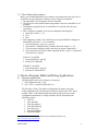
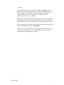
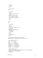
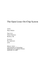
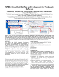
The following diagram describes the relationship between the system exception
handler and task exception handler.
Figure2 Task Exception Handler
[Y.F. Zhao2]
TASK A
TASK B
System Exception Handler
Exception Occurs
Task
The system exception handler is only one to handle all system exceptions.
Whereas each task owns an independent task exception handler.
When an exception occurs during task running, the system exception handler be
executed first. After the system exception handler has finished execution, the
task exception handler of the current running task starts to run.
For the JSP, add the following definition in the configuration file to install the
system exception handler:
DEF_EXC(SYS_EXC_ID, { TA_HLNG, sys_exc_handler });
SYS_EXC_ID
: System Exception ID
Sys_exc_handler : System exception handler name that must be
implemented in the C file.
Add the following definition in the configuration file to attach the task
exception handler to the task:
DEF_TEX(TASK_ID, { TA_HLNG, tsk_exc_routine });
TASK_ID
: Task ID attached
tsk_exc_routine : Task exception handler name that must be
implemented in the C file.
5.2.2 Installing the Interrupt Handler
In the LatticeMico32 system, the maximum interrupt number is 32.
March, 2008
14
In the JSP for LatticeMico32, the timer and UART have occupied two interrupt
numbers. Therefore, the interrupt number left for the user is 30.
The default interrupt number of the timer is 0.
The default interrupt number of the UART is 1.
In the JSP for LatticeMico32, the interrupt handler of low priority tasks can be
preempted by that of a high priority task. Smaller interrupt number means
higher interrupt priority.
Add the following definition in the configuration file to install the system
exception handler:
DEF_INH(INHNO_DEV, { TA_HLNG, dev_intr_handler });
INHNO_DEV
: Device Interrupt Number
dev_intr_routine : Interrupt handler for the device
5.2.3 Boot
As mentioned before, the storage component can be one of the following
components:
1. Internal RAM only
In this case, before building the images, the starting address and size in the link
file should be modified, (details please refer to the Appendix6.5), then build the
OS image refer to the Section 4.2 Build Applications. About how to program
the binary file to the Internal RAM refer the following example steps:
Step1: Open the LatticeMico32 System Cygwin Shell and enter the test
destination directory.
Step2: Run the following command in the shell:
$ bin_to_verilog --EB --width 4 jsp.bin EBR.mem
Step3: Use the generated memory initialization file EBR.mem to initialize
EBR in FPGA. Details see the Appendix6.3.
Step4: Use the ispVM download the generated bitstream to the FPGA, then
the application is working.
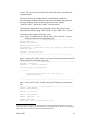
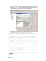
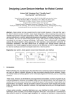
2. Flash + External SRAM
In this case, you need to program a boot-loader that loads the image
from the flash to the external SRAM.
March, 2008
15
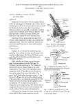
The following example steps describe the flow facility.
0x02000000
OS Image (Run)
jsp.bin
Externel SRAM
(0x2000000 – 0x20FFFFF)
0x020FFFFF
0x04000000
Boot-loader
boot.bin
Flash
(0x4000000 – 0x41FFFFF)
0x04080000
OS Image (Store)
jsp.bin
0x041FFFFF
0xFFFFFFFF
Figure3: Image Distribution Chart.
Step 1: Build the OS image. Because the OS image runs in the external SRAM.
The start address and length in the link file “config\lm32\ECP2\lm32elf.ld”
should be equal to that of the external SRAM. Details refer to the Appendix6.6
About how to build the OS image, refer to the Section 4.2 Build Applications.
Step 2: Program a boot-loader that copy the OS image from the flash to the
external SRAM. After copying is complete, the boot-loader jumps to the
external SRAM and continue to run.
The boot-loader source code can be found in the directory “src\boot\”.
In the header file “boot.h”, the parameters are defined.
SRAM_START_ADDRESS :
The SRAM start address. In the above example, it’s 0x02000000.
SRAM_SIZE
The size of the SRAM. In the above example, it’s 0x00100000.
FLASH_OS_ADDRESS
The start address where the OS image was stored in the flash. The
above example, it’s 0x04080000.
OS_IMAGE_SIZE
The size of the OS image. It can be gotten from the OS image file
March, 2008
16
(jsp.bin)
The OS image (jsp.bin) was stored from the address 0x4080000 in the
flash. The size of the image can be gotten from the OS image file (jsp.bin)
In the example, the flash address is from 0x4000000 to 0x41FFFFF.
If the flash address or size is changed, the corresponding link file
(src\boot\ boot.ld) need to be modified.
About how to build the boot-loader image, you can run the “LatticeMico32
System SDK Shell” firstly. Then enter the directory “src\boot” and type the
command “make” in the shell, then boot.bin generates under the src\boot.
Step 3: Program the boot-loader image (boot.bin) and the OS image (jsp.bin)
to the flash, Details please refer to Appendix6.4.
Step 4: After successfully write the boot.bin and jsp.bin to the flash, open
the Hyper Terminal and set it correctly, then Reset or re-power_up the
evaluation board, the application is working.
March, 2008
17
6
Appendix
6.1 Tested Boards List
The porting JSP was tested on the following three board, details please refer to
the release package JSP for lm32 v1.2/test/
• ECP2 LatticeMico32/DSP development board
• ECP2M PCI express platform evaluation board
• LatticeSC™ communications platform evaluation board
6.2
Example Platform Map
The example platform is based on the LatticeMico32/DSP Development Board
(ECP2)5. Refer to the following tables for settings of the platform memory map:
Boot from Flash:
Component
From
End
Size (byte)
External Sram
Flash
Timer
Uart
0x02000000
0x04000000
0x80000100
0x80000180
0x020FFFFF
0x05FFFFFF
0x8000017F
0x800001FF
0x00100000
0x02000000
0x00000080
0x00000080
Interrupt
Number
N/A
N/A
0
1
Boot from Internal RAM (EBR):
Component
From
End
Size (byte)
EBR
External Sram
Timer
Uart
0x00100000
0x00200000
0x80000100
0x80000180
0x00107FFF
0x002FFFFF
0x8000017F
0x800001FF
0x00008000
0x00100000
0x00000080
0x00000080
Interrupt
Number
N/A
N/A
0
1
6.3 Initializing the Memory Component
Now you load the memory initialization file into a placed and routed FPGA bitstream.
To implement the .mem file in an ispLEVER design:
1. In ispLEVER, double-click Place & Route Design.
2. In the Project Navigator toolbar, choose Tools > Memory Initialization Tool or
click or double-click Memory Initialization in the Processes for Current Source
window of the Project Navigator.
3. Click Load, browse to the .ncd file or type its name in the File Name box, and click
Open.
4. In the EBR Memories in Design panel, select {OCM}/ram, where {OCM} is the
name of the on-chip memory component from the LatticeMico32 platform.
5. Ensure that Memory Format is set to HEX.
6. In the Memory File box, browse to and select the on-chip memory initialization
(.mem) file created by LatticeMico32.
7. Click Apply Change.
8. Click Save, and dismiss the Save Design panel.
9. Click Exit.
10. In the Project Navigator, double-click Generate Bitstream Data.
6.4 How to Program the OS image (jsp.bin) and the boot-loader image
boot.bin to the flash.
Using the example project “CFIFlashProgrammer” include in the
LatticeMico32 system to write the flash. Following is the steps:
5
For details about the board, refers to “LatticeMico32/DSP Development board users guide” and
“LatticeMico32/DSP Development Kit user’s Guide for LatticeECP2”.
March, 2008
18
Step1. Open the mico32 development system and build up one new project by click
the menu “File -> New -> Mico32 Managed Make Project Wizard” and select the
“CFIFlashProgrammer” in the option “Select Project Templates”.
Step2: Build the project successfully and the elf file is generated.
Step3: Two files (flashprog.bin and flashprog.txt) should be added to the project
root directory.
flashprog.bin : The image you want to write to the flash, Binary data must be
contained in a binary file named flashprog.bin and binary datafile containing the data
for programming must be a multiple of 4-bytes.
flashprog.txt : a text file must contain two lines, the first line must contain the
absolute flash-address where the data needs to be programmed and the second line must
contain the size of image to program, specified as bytes. Flash address where the binary
data want to be programmed is expected to be aligned on a word (4-bytes) boundary.
For example:
According to the Figure3, assume to program the OS image (jsp.bin) to the flash
address 0x04080000, file size is 31764(bytes).
1. Copy the jsp.bin to the “CFIFlashProgrammer” project root directory and rename
the file name “jsp.bin” to “flashprog.bin”
2. Create one text file named “flashprog.txt” in project root directory, the content of
the text file as following:
0x4080000
31764
March, 2008
19
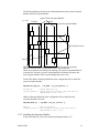
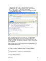
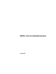
Step4: Select the "Run"->"Run ..." in the LatticeMico32 system GUI.
A window named "Run" will show and double click the "mico32 hardware".
set the "Project :" and "C/C++ Application" in the tab "Main".
Click the button "Run", the console terminal shows you the flash write is done.
Following is the captured picture
Step5: Delete the flashprog.bin, copy the boot.bin to the “CFIFlashProgrammer”
project root directory and rename the boot.bin to flashprog.bin, then open the
flashprog.txt and modify the two lines, the first line was modified to 0x04000000
according to the Figure3, the second line was updated to 768 (bytes) according to the
size of the boot.bin.
Step6. Go to Step4. Repeat the step5, step6 and step4 can write many images to the
target flash many times as you like.
6.5 Link file for Store and Run the image in the internal memory
/*
* @(#) $Id: lm32elf.ld,v 1.14 2007/07/27 11:28:44 honda Exp $
*/
OUTPUT_FORMAT("elf32-lm32")
March, 2008
20
ENTRY(reset)
/*
* This section defines memory attributes (name, origin, length) for the platform
*/
MEMORY
{
ebr : ORIGIN = 0x00100000, LENGTH = 32768
sram : ORIGIN = 0x00200000, LENGTH = 1048576
}
SECTIONS
{
/* code */
.boot : { *(.boot) } > ebr
.text :
{
. = ALIGN(4);
_ftext = .;
*(.text .stub .text.* .gnu.linkonce.t.*)
*(.gnu.warning)
KEEP (*(.init))
KEEP (*(.fini))
/* Exception handlers */
*(.eh_frame_hdr)
KEEP (*(.eh_frame))
*(.gcc_except_table)
/* Constructors and destructors */
KEEP (*crtbegin*.o(.ctors))
KEEP (*(EXCLUDE_FILE (*crtend*.o ) .ctors))
KEEP (*(SORT(.ctors.*)))
KEEP (*(.ctors))
KEEP (*crtbegin*.o(.dtors))
KEEP (*(EXCLUDE_FILE (*crtend*.o ) .dtors))
KEEP (*(SORT(.dtors.*)))
KEEP (*(.dtors))
KEEP (*(.jcr))
_etext = .;
} > ebr =0
/* read-only data */
.rodata :
{
. = ALIGN(4);
_frodata = .;
_frodata_rom = LOADADDR(.rodata);
*(.rodata .rodata.* .gnu.linkonce.r.*)
March, 2008
21
*(.rodata1)
_erodata = .;
} > ebr
/* read/write data */
.data :
{
. = ALIGN(4);
_fdata = .;
*(.data .data.* .gnu.linkonce.d.*)
*(.data1)
SORT(CONSTRUCTORS)
_gp = ALIGN(16) + 0x7ff0;
*(.sdata .sdata.* .gnu.linkonce.s.*)
_edata = .;
} > ebr
/* bss */
.bss :
{
. = ALIGN(4);
_fbss = .;
*(.dynsbss)
*(.sbss .sbss.* .gnu.linkonce.sb.*)
*(.scommon)
*(.dynbss)
*(.bss .bss.* .gnu.linkonce.b.*)
*(COMMON)
. = ALIGN(4);
_ebss = .;
_end = .;
PROVIDE (end = .);
} > sram
/* first location in stack is highest address in ram */
PROVIDE(_fstack = ORIGIN(sram) + LENGTH(sram) - 4);
/* stabs debugging sections. */
.stab
0 : { *(.stab) }
.stabstr
0 : { *(.stabstr) }
.stab.excl 0 : { *(.stab.excl) }
.stab.exclstr 0 : { *(.stab.exclstr) }
.stab.index 0 : { *(.stab.index) }
.stab.indexstr 0 : { *(.stab.indexstr) }
.comment
0 : { *(.comment) }
/* DWARF debug sections.
Symbols in the DWARF debugging sections are relative to the beginning
of the section so we begin them at 0. */
/* DWARF 1 */
March, 2008
22
.debug
0 : { *(.debug) }
.line
0 : { *(.line) }
/* GNU DWARF 1 extensions */
.debug_srcinfo 0 : { *(.debug_srcinfo) }
.debug_sfnames 0 : { *(.debug_sfnames) }
/* DWARF 1.1 and DWARF 2 */
.debug_aranges 0 : { *(.debug_aranges) }
.debug_pubnames 0 : { *(.debug_pubnames) }
/* DWARF 2 */
.debug_info 0 : { *(.debug_info .gnu.linkonce.wi.*) }
.debug_abbrev 0 : { *(.debug_abbrev) }
.debug_line 0 : { *(.debug_line) }
.debug_frame 0 : { *(.debug_frame) }
.debug_str
0 : { *(.debug_str) }
.debug_loc
0 : { *(.debug_loc) }
.debug_macinfo 0 : { *(.debug_macinfo) }
/* SGI/MIPS DWARF 2 extensions */
.debug_weaknames 0 : { *(.debug_weaknames) }
.debug_funcnames 0 : { *(.debug_funcnames) }
.debug_typenames 0 : { *(.debug_typenames) }
.debug_varnames 0 : { *(.debug_varnames) }
}
6.6 Link file for store the image in flash and run in the sram
/*
* @(#) $Id: lm32elf.ld,v 1.14 2007/07/27 11:28:44 honda Exp $
*/
OUTPUT_FORMAT("elf32-lm32")
ENTRY(reset)
/*
* This section defines memory attributes (name, origin, length) for the platform
*/
MEMORY
{
sram : ORIGIN = 0x02000000, LENGTH = 1048576
}
SECTIONS
{
/* code */
.boot : { *(.boot) } > sram
.text :
{
. = ALIGN(4);
_ftext = .;
*(.text .stub .text.* .gnu.linkonce.t.*)
*(.gnu.warning)
March, 2008
23
KEEP (*(.init))
KEEP (*(.fini))
/* Exception handlers */
*(.eh_frame_hdr)
KEEP (*(.eh_frame))
*(.gcc_except_table)
/* Constructors and destructors */
KEEP (*crtbegin*.o(.ctors))
KEEP (*(EXCLUDE_FILE (*crtend*.o ) .ctors))
KEEP (*(SORT(.ctors.*)))
KEEP (*(.ctors))
KEEP (*crtbegin*.o(.dtors))
KEEP (*(EXCLUDE_FILE (*crtend*.o ) .dtors))
KEEP (*(SORT(.dtors.*)))
KEEP (*(.dtors))
KEEP (*(.jcr))
_etext = .;
} > sram =0
/* read-only data */
.rodata :
{
. = ALIGN(4);
_frodata = .;
_frodata_rom = LOADADDR(.rodata);
*(.rodata .rodata.* .gnu.linkonce.r.*)
*(.rodata1)
_erodata = .;
} > sram
/* read/write data */
.data :
{
. = ALIGN(4);
_fdata = .;
*(.data .data.* .gnu.linkonce.d.*)
*(.data1)
SORT(CONSTRUCTORS)
_gp = ALIGN(16) + 0x7ff0;
*(.sdata .sdata.* .gnu.linkonce.s.*)
_edata = .;
} > sram
/* bss */
.bss :
{
. = ALIGN(4);
_fbss = .;
March, 2008
24
*(.dynsbss)
*(.sbss .sbss.* .gnu.linkonce.sb.*)
*(.scommon)
*(.dynbss)
*(.bss .bss.* .gnu.linkonce.b.*)
*(COMMON)
. = ALIGN(4);
_ebss = .;
_end = .;
PROVIDE (end = .);
} > sram
/* first location in stack is highest address in ram */
PROVIDE(_fstack = ORIGIN(sram) + LENGTH(sram) - 4);
/* stabs debugging sections. */
.stab
0 : { *(.stab) }
.stabstr
0 : { *(.stabstr) }
.stab.excl 0 : { *(.stab.excl) }
.stab.exclstr 0 : { *(.stab.exclstr) }
.stab.index 0 : { *(.stab.index) }
.stab.indexstr 0 : { *(.stab.indexstr) }
.comment
0 : { *(.comment) }
/* DWARF debug sections.
Symbols in the DWARF debugging sections are relative to the beginning
of the section so we begin them at 0. */
/* DWARF 1 */
.debug
0 : { *(.debug) }
.line
0 : { *(.line) }
/* GNU DWARF 1 extensions */
.debug_srcinfo 0 : { *(.debug_srcinfo) }
.debug_sfnames 0 : { *(.debug_sfnames) }
/* DWARF 1.1 and DWARF 2 */
.debug_aranges 0 : { *(.debug_aranges) }
.debug_pubnames 0 : { *(.debug_pubnames) }
/* DWARF 2 */
.debug_info 0 : { *(.debug_info .gnu.linkonce.wi.*) }
.debug_abbrev 0 : { *(.debug_abbrev) }
.debug_line 0 : { *(.debug_line) }
.debug_frame 0 : { *(.debug_frame) }
.debug_str
0 : { *(.debug_str) }
.debug_loc
0 : { *(.debug_loc) }
.debug_macinfo 0 : { *(.debug_macinfo) }
/* SGI/MIPS DWARF 2 extensions */
.debug_weaknames 0 : { *(.debug_weaknames) }
.debug_funcnames 0 : { *(.debug_funcnames) }
.debug_typenames 0 : { *(.debug_typenames) }
.debug_varnames 0 : { *(.debug_varnames) }
}
March, 2008
25
Page: 8
[Y.F. Zhao1]Group
the diagram
Page: 14
[Y.F. Zhao2]The
diagram is not grouped. Group the diagram.