1
4.1.
4.2.
4.3.
4.4.
4.5.
5.
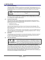
19-Inch Rack Mounting .......................................................................12
Ventilation Requirements ....................................................................12
Orientation...........................................................................................12
AC Power Connection.........................................................................12
Connecting the High Voltage Output ... Error! Bookmark not defined.
CONTROLS, INDICATORS, CONNECTORS.................................. 16
5.1. Front Panel Layout (L Model) .............................................................16
5.2. HV ON Push Button (Ref 1) ................................................................17
5.3. Status LEDs (Ref 2) ............................................................................17
5.4. Local Voltage Set (Ref 3) ....................................................................18
5.5. Voltage bar graph (Ref 4)....................................................................18
5.6. Voltage Display (Ref 5) .......................................................................18
5.7. HV OFF Push Button (Ref 6) ..............................................................18
5.8. Off/Local/Remote Keyswitch (Ref 7)...................................................18
5.9. View set push button (Ref 8)...............................................................18
5.10.Current bar graph (Ref 9) ......................................................................18
5.11.Current Display (Ref 10)........................................................................18
5.12.Power switch (Ref 11) ...........................................................................19
5.13.Front Panel Layout (S Model) ...............................................................19
5.14.Rear Panel Layout (L Models) ..............................................................19
5.15.Rear Panel Layout (S Models) ..............................................................21
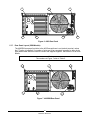
5.16.Rear Panel Layout (OEM Models) ........................................................22
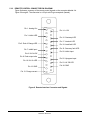
5.17.REMOTE CONTROL CONNECTOR PIN DIAGRAM ...........................23
6.
OPERATING INSTRUCTIONS ........................................................ 24
6.1.
6.2.
6.3.
6.4.
7.
Local Operation (402L only)................................................................24
Remote Operation (All models)...........................................................25
Remote Control Sequence..................................................................28
Parallel Operation ...............................................................................29
APPLICATION NOTES ................................................................... 34
2
83487001 Revision F