1
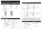
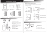
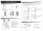
! MultiBio 700 Installation Guide Version: V1.1 Warning: No operating with power on Date: Nov. 2011 3.Lock Connection 1. Equiment Installation (1) Shares power with the lock: + In st ru ct io n fo r th e Mo un ti ng P ap er BELLBELL+ SEN GND DC12V Be fo re t he d ev ic e is f as te ne d, p le as e st ic k th e pa pe r to t he p la ce w he re y ou wa nt t o in st al l it , th en m ak e ho le s an d la y ca bl es a cc or di ng t o th e mo un ti ng pa pe r. Wiring Hole NC LOCK - 12 FR 107 (2) Remove the screw on the bottom (1) Post the mounting template on the wall.Drill the holes according to the marks on the template (holes for screw and wiring). (3) Take away the back plate. + of device. NO LOCK BUT ULOCK=12V, I-ILOCK>1A…… ① And the lock is near to the device. NO COM NC AL+ AL- + (2) Does not share power with the lock: - GND + BELLBELL+ SEN GND DC12V DC power - BUT + FR 107 (4) Fix the back plate on the wall according to the mounting paper. (5) Fix the device to the back plate. + - Device does not shares power with the lock: DC12V FR 107 + NO LOCK BELLBELL+ SEN GND BUT DC power B . ULOCK ≠12V; C. The lock is far apart from the device. NO COM NC AL+ AL- + A. ULOCK =12V I-ILOCK ≤ 1A; with ‘NO’ terminal, and the NC LOCK is connected with ‘NC’ terminal. Access Control System Function (1) If a registered user verified, the device will export the signal to unlock the door. TCP/IP ⑦ RS232/RS485 Converter NC LOCK NO COM NC AL+ AL- +12V GND (1) The system supporst NO LOCK and NC LOCK. For example the NO LOCK (normally open at power on) is connected 2. Structure and Function Exit Button ⑤ (2) Door sensor will detect the on-off state. If the door is un- (2) When the Electrical Lock is connected to the Access Cont rol System, you need to parallel one FR107 diode (equipped in the package) to prevent the self-inductance EMF affecting the system, do not reverse the polarities. 4. Connected with other parts: expected opened or improperly closed, the alarm signal ④ (digital value) will be triggered. Door Bell Lock Sensor (3) As the d evice is removed illegally , it will output an alarm signal. SEN (4) External card reader is supported. Door Bell External Reader Exit Button Alarm Power (5) External exit button is supported, it is convenient to open the Alarm door inside. (6) External door bell is supported. ③ Alarm (7) Supports RS485 , TCP/IP modes to connect with PC. One PC can manage multiple devices. Input DC 12V, 500mA (50mA standby) BELL+ Positive is connected with ‘+12V’, negative is connected with ’GND’ (do not reverse the polarities). GND BUT EXIT BUTTON 5. Connected with Power: BELL- EXIT BUTTON ⑥ ② FR 107 NO COM NC AL+ AL- +12V ① Device shares power with the lock: BELLBELL+ SEN GND DC12V + RS485 +12V GND - BUT 10 11 + +12V GND - MultiBio 700 Mounting Paper (only for your reference) NO COM NC AL+ AL- + Door Sensor - + - DC12V Voltage output ≤ DC 12V for Alarm ①:‘I’: device output current, ‘ ULOCK ILOCK ’: lock voltage,’ ’: lock current +12V GND ! 6. Wiegand Output Warning: No operating with power on 7. Wiegand Input The device supports standard Wiegand 26 output, The device has the function of Wiegand signal input . It s upports to as a reader device it has a very good compatibility. connect with an independent card reader. They are installed each side of the door, to control the lock and access together. (2) RS485 Mode: 485+ 485- Please use specified RS485 wire, RS485 active converter and bus-type wiring. 485+ 485- Terminals: +12V 485Access Control 12Vout 485+ GND GND IWD1 TXD IWD0 DATA1 DATA1 DATA0 Terminals PC Serial Ports 485+ RS485+ 485- RS485- RS485 Bus 485+ 485- 485+ 485- RS485 Converter RLED RXD RLED GND DATA0 GND GND GLED WD 0 BEEP GLED BEEP (3) TCP/IP Mode: WD 1 (1) Please keep the distance between the device and Access Control or Card Reader less than 90 meters(Please use Wiegand signal extender in long distance or interference environment). (2) To keep the stability of Wiegand signal, connect the device and the Access Control or Card Reader in same ‘GND’ in any case. (A) Crossover cable: The device and PC connected directly. (B) Straight cable: The device and PC connected to LAN/WAN through switch/Lanswitch. PC 8.Other Functions Switch IP Address:192.168.1.100 Subnet Mask:255.255.255.0 (1) Manual Reset: … If the device does not work properly because of misoperation or other abnormality, you can use ‘Reset’ function to restart it. Side View Back View IP Address:192.168.1.124 Operation: Remove the black rubber cap, then stick the Reset button Subnet Mask:255.255.255.0 hole with a sharp tool (the tip diameter less than 2mm). (2) Recovery Factory Settings: You can use the tamper switch to recovery factory setting, such as device number, system password, IP address, RS485 address, etc. More information please refers to the user manual. 10. Cautions: Operation: Press the tamper switch three times after the alarm being triggered 30 seconds but no more than 60 seconds. Reset Button Tamper Switch Note: The user data won’t be cleared. (1)Power cable is connected after all the other wiring. If the device is working abnormally, please shut down the power first, then make the necessary check . Kindly reminds you that any hot-line work may damage the device, and it is not included in the warranty. (2)We recommend the 3A/12V DC Power supply. Please contact our technical staff for details. 9. Communication (3 )Please read the terminals description carefully and wiring by rule strictly. Any damage caused by improper operations will not under warranty. There are three modes that the PC software communicate and exchange information with the device: RS232, RS485 and TCP/IP, and the last two mode support remote control. (1) RS232 Mode: (4)Keep the exposed part of wire less than 5mm, to avoid unexpected connection. Terminals: Terminals PC Serial Ports GND RXD Pin5-Gnd Pin3-Txd TXD Pin2-Rxd (5)Please connect the ‘GND’ before all the other wiring especially under the environment, to prevent the overlarge instantaneous electrostatic to damage device. (6)Do not change the cable type because of long distance between the power and the device. (7) Please use specified RS485 wire, RS485 active converter and bus-type wiring. 2. Main Menu 2. Main Menu There are two types of rights respectively granted to two types of users: the Ordinary users and administrators. Ordinary users are only granted the rights of face, fingerprint, password or card verification, while administrators are granted access to the main menu for various operations apart from having all the privileges granted to ordinary users. Press [Menu] on the initial interface to access the main menu, as shown in the following figure: The main menu includes nine sub menus: Add User: Through this submenu, you can add a new user and input the information on the device, including the user ID, name, fingerprint, face, card, password, rights, group No. and user access. User Mgt.: Through this submenu, you can browse the user information stored on the device, including the user ID, name, fingerprint, face, card, password, rights, group No. and user access. Here you can also add, 21 3 inches Facial & Fingerprint Recognition Series Product User Manual modify or delete a user’s information. Comm.: Through this submenu, you can set related parameters for communication between the device and PC, including the IP address, gateway, subnet mask, baud rate, device No. and communication password. System: Through this submenu, you can set system-related parameters, including the basic parameters, interface parameters, fingerprint, face and attendance parameters, Keyboard definitions, Access settings, firmware update etc. to enable the device to meet the user’s requirements to the greatest extent in terms of functionality and display. Data Mgt.: Through this submenu, you can perform management of data stored on the device, for example, deleting the attendance records, all data, clear administrator, restore to factory settings and query records. Date/Time: Through this submenu, you can set the alarm time and duration, or set the Bell. Auto Test: This submenu enables the system to automatically test whether functions of various modules are normal, including the screen, sensor, voice, face, keyboard, clock tests and screen calibration. Dn/Upload: Through this submenu, you can download user information and attendance data stored in the device through a USB disk to related software or other fingerprint recognition equipment. Sys Info.: Through this submenu, you can browse the records and device 22 2. Main Menu information. Any user can access the main menu by pressing the [Menu] key if the system does not have an administrator. After administrators are configured on the device, the device needs to verify the administrators’ identity before granting them access to the main menu. To ensure device security, it is recommended to set an administrator when using the terminal initially. For detailed operations, see 3.8 Modifying User Right. 23 3 inches Facial & Fingerprint Recognition Series Product User Manual 3. Add User Press [Add] on the [User Mgt.] interface to display the [Add User] interface as shown below. User ID: Enter a user ID. 1 to 9 digits user IDs are supported by default. Name: Enter a user name. 12 characters user names are supported by default. Fingerprint: Enroll a user’s fingerprint and the device displays the number of enrolled fingerprints. A user can enroll 10 fingerprints at maximum. Password: Enroll a user’s password. The device supports 1-8 digit passwords by default. Face: Enroll a user’s face. Group No.: Setting in the group of user. Role: Set the rights of a user. A user is set to ordinary user by default and can also be set to administrator. Ordinary users are only granted the rights of face, fingerprint or password verification, while administrators are granted access to the main menu for various operations apart from having all the privileges granted to ordinary users. Photo: Enroll a user’s photo. During user verification is success; the user’s photo is displayed on screen. User Access: Set the lock control and access control parameters. 24 Error! Use the Home tab to apply 标题 1 to the text that you want to appear here. 3.1 Entering a User ID The device automatically allocates an ID starting from 1 for every user in sequence. If you use the ID allocated by the device, you may skip this section. 1. Press [User ID] on the [Add User] interface to display the user ID management interface. Tip: The user ID can be modified during initial enrollment, but once enrolled, it cannot be modified. 2. On the displayed keyboard interface, enter a user ID and press [OK]. If the message “The user ID already exists!” is displayed, enter another ID. Tip: The device supports 1 to 9 digits user IDs by default. If you need to extend the length of current user ID numbers, please consult our commercial representatives or technical pre-sales. 3. After the user ID is entered, press [Save] to save the current information and return to the previous interface. Press [Exit] to return to the previous interface without saving the current information. 25 3 inches Facial & Fingerprint Recognition Series Product User Manual 3.2 Entering a Name Use T9 input method to enter the user name through the keyboard. 1. Press [Name] on the [Add User] interface to display the name input interface. 2. On the displayed keyboard interface, enter a user name and press [X]. For details of operations on the keyboard interface, see 12.1 T9 Input Instructions. 3. After the user name is entered, press [Save] to save the current information and return to the previous interface. Press [Exit] to return to the previous interface without saving the current information. Tip: The device supports the 1 to 12 characters names by default. 26 Error! Use the Home tab to apply 标题 1 to the text that you want to appear here. 3.3 Enrolling a Fingerprint 1. Press [Fingerprint] on the [Add User] interface to display the [Enroll Fingerprint] interface. 2. On the displayed [Enroll Fingerprint] interface, place your finger on the fingerprint sensor properly according to the system prompt. For details, see 1.3 Finger Placement. 3. Place the same finger on the fingerprint sensor for three consecutive times correctly. If the enrollment succeeds, the system will display a prompt message and automatically return to the [Add User] interface. If the enrollment fails, the system will display a prompt message and return to the [Enroll Fingerprint] interface. In this case, you need to repeat the operations of step 2. 4. You can enroll the backup fingerprint by pressing [Fingerprint] again. A user can enroll 10 fingerprints at maximum. 5. Press [Save] to save the current information and return to the previous interface. Press [Exit] to return to the previous interface without saving the current information. 27 3 inches Facial & Fingerprint Recognition Series Product User Manual 28 Error! Use the Home tab to apply 标题 1 to the text that you want to appear here. 3.4 Enrolling a Password 1. Press [Password] on the [Add User] interface to display the password management interface. 2. On the displayed keyboard interface, enter a password and press [OK]. Re-enter the password according to the system prompt and then press [OK]. Tip: The device supports 1-8 digit passwords by default. 3. After the password is entered, an interface is displayed as shown below. Press [Save] to save the current information and return to the previous interface. Press [Exit] to return to the previous interface without saving the current information. 29 3 inches Facial & Fingerprint Recognition Series Product User Manual 3.5 Enrolling an ID card 1. Press [Card] on the [Add User] interface to display the [Enroll Card] interface. 2. The [Punch Card!] interface pops up as shown below. Swipe your ID card properly in the swiping area. For details, see 1.6 Appearance of Device. 3. If the card passes the verification, the device will display a prompt message “Read Successfully! Card No.: **********”, and returns to the [Add User] interface. 4. Press [Save] to save the current information and return to the previous interface. Press [Exit] to return to the previous interface without saving the current information. Note: 3 inches Facial & Fingerprint Recognition support Mifare card function. It is an option function, if you want to customize the Mifare card function, please consult our commercial representatives or pre-sales technical support engineers. 30 Error! Use the Home tab to apply 标题 1 to the text that you want to appear here. 3.6 Enrolling a Face 1. Press [Face] on the [Add User] interface to display the face enrollment interface. 2. On the displayed face enrollment interface, turn your head to the left and right slightly, raise and lower your head according to the voice prompts, so as to enroll different parts of your face into the system to assure the accurate verification. See 1.2 Enrollment Face Expressions. 3. If your face image is enrolled successfully, the system will display a prompt message and automatically return to the [Add User] interface. 4. Press [Save] to save the current information and return to the previous interface. Press [Exit] to return to the previous interface without saving the current information. 31