1
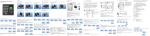
SF series user manual V1.0
SF100 User Manual
Version 1.0
SF series user manual V1.0
Contents
1 Profile............................................................................................................... 1
1.1 Basic function parameters ........................................................................... 1
1.2 Panel introduction....................................................................................... 2
2. System Installation .......................................................................................... 4
2.1 Installation Notices ..................................................................................... 4
2.2 Device Installation ...................................................................................... 5
2.3 Sketch Map of System Installation............................................................... 7
3. Connection with the peripheral devices .......................................................... 8
3.1 Connection with access controller (only SF101)..................................... 8
3.2 Connection with door lock .......................................................................... 9
3.3 Connections with exit button, alarm, doorbell, and door sensor................... 11
3.4 Power supply............................................................................................ 13
4. Basic operations ............................................................................................ 14
4.1 Enroll a administrator................................................................................ 16
4.2 Enroll a user ............................................................................................. 17
4.3 User authentication ................................................................................... 18
4.4 Delete a user............................................................................................. 19
4.5 Delete all users ......................................................................................... 20
4.6 Fingerprint enrollment sub-flow and overtime judgement sub-flow ............ 21
5. Communications ........................................................................................... 23
SF series user manual V1.0
1 Profile
1.1 Basic function parameters
Features
Easy installation, high reliability
Simple and clear operation flow, voice prompts in the operations.
Support the ID / MF card, a wider use range.
Support the backup authentication, stronger function (also with the
extension function).
Basic function parameters are shown as follows:
Power
DC12V
Function
Access control device, has the
detection functions such as door
sensor, device dismantled etc.
One Wiegand output (only SF101)
User number
200 (fingerprint, ID card and MF
card)
Record memory
30000 records
communication
USB
RS232/485
running)
(device
monitors the
Fingerprint head
Optical fingerprint head
Door bell
Support the wired doorbell
Speaker
The voice prompts
Buzzer
Alarm when the device is dismantled
LED
Three-color indicate (Red, green,
All copyrights are reserved
-1-
SF series user manual V1.0
blue)
Language
Support multi-national voices
Sleep
Support the sleep function
Explanation:
1. Access control function: support the access control output, door
sensor alarm, exit button, but not support time segment, duress alarm etc.
It is a comparatively simple access control.
2. Sleep function: during sleeping, the backlight of fingerprint head is
turned off and Led displays, if any key is pressed (except the Bell key),
it will be waked up automatically to work normally.
1.2 Panel introduction
Front panel
LED:
the indicator light with three colors of red,
Enroll key: it is
also used as
exit key during
the enrollment.
Delete key: it is
also used as
exit key during
the deletion.
Fingerprint
reader
finger
buckle
cover
doorbell key
All copyrights are reserved
-2-
SF series user manual V1.0
Back panel:
Anti-dismantle button: Send
out the alarm signal through
the terminal when the device
Speaker (mainly used in voice prompt)
Bottom Panel
USB interface
Reset key
Press this key to restart device if
device can not run normally due to
the error operations or other
accidents.
All copyrights are reserved
-3-
SF series user manual V1.0
2. System Installation
2.1 Installation Notices
Our products are mass-produced and in accordance with the strict
production and testing standards in China, the United States and the
European Union, but we hope you read the installation notices carefully
before the installation. The company to remind you the proper use, will
greatly improve your use effect and speed. If you don’t read the notes
carefully before the installation, probably because of improper
installation will cause a very serious accident damage, even though
we make every effort to provide you with good service, and you will
have to pay an unnecessary price.
1. Please connect the power supply later after all other wires are
connected well. If the machine cannot run normally, please cut off the
power and then start examination. Please remember: All connection
wires with power will damage the machine accidentally. We won’t
provide maintenance for such damage.
2. Recommend the use of 3A/12V DC power supply to the equipment.
For details, consult the relevant technical staff.
3. Please firstly read explanations of connection terminals carefully
and then connect the wires in strict accordance with the rules, due
to abnormal operations may result in equipment damages, do not
belong to the scope of warranty
4. All external connection wires are forbidden to be bared, both
connections and useless ends of wires must be bandaged with insulating
tape to prevent the accident contact of bared wires, which cause the
machine damage.
All copyrights are reserved
-4-
SF series user manual V1.0
5. To prevent excessive instantaneous electrostatic damage to the
machine in winter or the place with a comparatively serious static,
please connect the ground wire firstly, then connect the other wires.
6. If the distance between power supply and machine is long, please
don't use the net cable or other types of lines to take place of power cord.
While selecting power cord, voltage attenuation caused by overlong
transmission distance should be taken into account.
7. When use 485 to organize a network, please use the professional
485 bus and RS232/485 transformer with power, and adopt the bus-type
wiring. If RS485 communication distance is over 300 meters, add a
terminal matched resistor about 120Ω to the RS485 bus.
8. Please use the access control software to connect the machine and
enroll users.
2.2 Device Installation
1) Post the moulding board on the
wall. Drill holes according to marks
on the moulding. (There should be
screw holes and lead wire hole)
All copyrights are reserved
2) Take the waterproof glue
away from the rear cover
-5-
SF series user manual V1.0
3) Take the finger buckle
cover away from the device
4) Use screws to fix the device and
waterproof glue on the wall.
5)At last, install the finger buckle
cover well to complete the device
installation.
All copyrights are reserved
-6-
SF series user manual V1.0
2.3 Sketch Map of System Installation
1.When a person has passed the status authentication on the access
control device, the device will output the lock control signal to unlock.
2. Door sensor will automatically detect the switch state, when the door
is accidentally opened or the door is not closed well, it will trigger the
alarm signal (switch volume signal)
3. If the access control device is in unusual circumstances such as illegal
demolition etc., it will output the alarm signal (switch volume signal).
4. External wired doorbell can be connected.
5. External exit button can be connected, so it is convenient to open the
door from the indoors.
6. Through RS485/RS232/USB to connect with PC and transfer data to
PC, you can easily manage multiple terminal devices through access
control management software.
Note: The alarm and the wired doorbell are required to connect an
external power supply
All copyrights are reserved
-7-
SF series user manual V1.0
3. Connection with the peripheral devices
3.1 Connection with access controller (only SF101)
SF100 as a fingerprint reader, can support various Wiegand format outputs,
and can connect with access controllers of majority manufacturers on the
market. Wiegand output has two modes as follows:
The mode to output user number: Wiegand outputs the fingerprint or
the user number after a successful card authentication, or the instruction
code after a failed authentication.
The mode to output card: Wiegand outputs the got card data, that is,
to output the card data as the original.
Note: 1) The recommended distance between device and access controller
should not be more than 90 meters (If a longer distance or an environment
with interference, please use the Wiegand signal extender).
2) Regardless of whether the device shares power supply with the access
controller, the device must share the ground with the access controller to
guarantee the stability of Wiegand signal.
3) Since SF100 and SF101 can not be used as readers, RLED, GLED, BEEP
are the idle terminals. In addition, SF100 has no Wiegand output, so 12V,
GND, WD0 and WD1 are also the idle terminals.
All copyrights are reserved
-8-
SF series user manual V1.0
3.2 Connection with door lock
The device is able to support NO (normally open) and NC (normally
closed) locks, only if connected with different terminals. NO terminal
should be used for NO lock, which is open during power on and closed
during power off. And NC terminal should be used for NC lock, which
is closed during power on and opened during power off.
1. Device and lock share power supply
※Note: In case that device and lock share the power supply:
When ULOCK=12V, I-ILOCK>1A((thereinto, ULOCK is the operate
voltage of lock, I is the output current of device’s power supply, ILOCK is
the operate current of lock.) And the distance between lock and device is
closer.
(1) NC lock
SF series
All copyrights are reserved
-9-
SF series user manual V1.0
(2) NO lock
SF series
2. Device and lock do not share power supply
※Note: In case that device and lock don’t share power supply:
1)ULOCK=12V and I-ILOCK≤1A;
2)ULOCK≠12V;
3) A long distance between device and lock.
(thereinto, ULOCK is the operate voltage of lock, I is the output current of
device’s power supply, ILOCK is the operate current of lock.)
(1)NC lock
SF series
DC Power
Normally closed
All copyrights are reserved
-10-
SF series user manual V1.0
(2)NO lock
SF series
Normally open
DC Power
3.3 Connections with exit button, alarm, doorbell, and door
sensor
SF series
All copyrights are reserved
-11-
SF series user manual V1.0
3.3.1 Door sensor
Door sensor is used to detect the door’s on/off status. The fingerprint
access control device can use it to detect the door is opened illegally,
and at this time it will output the alarm. In addition, if the opened door is
not closed well in the regulated time, it also will output the alarm
3.3.2 Exit button
Exit button is a door-open switch installed inside the room and it is
closed to open the door. Please fix it at a place which is about 1.4 meter
high from the ground. Please ensure its location is positive and not
askew, while its connection is accurate and firmly. (Cut off the bared
side of unused cable and wrap it with the insulating tape.) Please pay
attention to prevent the electromagnetic interference. (For example:
lighting switch, computer, etc)
3.3.3 Alarm
The alarm output of this fingerprint access control device is an on-off
signal. It can be put in series to the power circuit of a simple alarm. Of
course, it can also be used as a trigger signal of the advanced alarm or
the monitoring system. (The alarm output of the device only supports
the 12VDC alarm.)
3.3.4 Doorbell
The device can only use the doorbell with control pin. The doorbell
connected with power supply directly is not recommended.
All copyrights are reserved
-12-
SF series user manual V1.0
3.4 Power supply
The device’s working power is DC12V. The working current is less than
300mA and the standby current is less than 200mA. Connect the
positive and negative poles of power supply between +12V and AGND
directly to work normally. (Don’t connect the positive and negative
poles in reverse.)
All copyrights are reserved
-13-
SF series user manual V1.0
4. Basic operations
When power on, the device is in authenticating state. At this time the
user can enter into the states of user enrollment, administrator
enrollment, delete a user, and empty users. Each process is prompted by
the voice and the indicator light.
The operation processes are described as follows:
1. In authenticating state, if no enrolled fingerprint and card, the voice
‘Please press the Enroll key long to enroll a administrator’ prompts the
user to enroll a administrator as soon as possible.
2. User must enroll at least one administrator firstly before the normal
users can be enrolled.
3. During the enrollment, if no operation consecutively for n seconds
(set by the user), duplicate the corresponding voice prompt. After two
times consecutively voice prompts, system will return to the
authenticating status automatically. In the deletion state, system will exit
as soon as the first overtime
4. MF card can only support the same and simple functions of ID card
such as the enrollment and the deletion.
5. During the enrollment or the deletion, if consecutively three times
failed confirmations by the user, system will return to the authenticating
state with the prompt voice ‘A failed administrator confirmation, system
will return to the authenticating state’
6. During the enrollment or the deletion, if press the Enroll key or the
All copyrights are reserved
-14-
SF series user manual V1.0
Delete key by the user, system will exit from the enrollment or the
deletion state automatically, and there are voice prompts.
7. During deleting a user, the last administrator can not be deleted.
8. During deleting a user, the administrator confirmation is not required,
but it is a must when delete all users.
9. When the enrolled fingerprints or cards are full, system will return to
the authenticating state with the prompt voice ‘Users are already full,
system exits!’.
10. There is a voice prompt when the records are full, and then the later
record can not be saved. At this time, users can mange the records by
connecting to the access control software.
11. Other Tips
a: In authenticating (verification)state, blue LED will flash once per
1/2 second. During enrollment and deletion, no flashed LED
displays.
b. If a successful authentication or enrollment or deletion, green led
will be constant on for a second; If a failed authentication or
enrollment or deletion, red LED will be constant on for a second.
c. When users open the door normally, 3 seconds after the lock is
locked up, if the device detects the door sensor has not been closed
well, the buzzer will work long to prompt; 1 minute later, if the
door sensor is still not closed well, the alarm will work.
All copyrights are reserved
-15-
SF series user manual V1.0
4.1 Enroll a administrator
The steps to enroll a administrator are shown in the following flow
chart:
Note: The overtime judgement sub-flow and the fingerprint enrollment
sub-flow, please refer to the section 4.6.
All copyrights are reserved
-16-
SF series user manual V1.0
4.2 Enroll a user
Each user can only enroll a fingerprint or a card, the range of user ID is
1~999.
The operation steps are shown as the following flow chat.
Note: The overtime judgement sub-flow and the fingerprint enrollment
sub-fow, please refer to the section 4.6.
All copyrights are reserved
-17-
SF series user manual V1.0
4.3 User authentication
The steps to authenticate users are shown as the following flow chart:
All copyrights are reserved
-18-
SF series user manual V1.0
4.4 Delete a user
The operation steps are shown as the following flow chart:
All copyrights are reserved
-19-
SF series user manual V1.0
4.5 Delete all users
The operate steps are shown as the following flow chart.
Note: The overtime judgement sub-flow, please refer to the section 4.6
All copyrights are reserved
-20-
SF series user manual V1.0
4.6 Fingerprint enrollment
judgement sub-flow
sub-flow
and
overtime
4.6.1 Fingerprint enrollment sub-flow
The operation steps are as the following flow chart.
All copyrights are reserved
-21-
SF series user manual V1.0
4.6.2 Overtime judgement flow when enrolling or deleting a user
The operation steps are shown as the following flow chart.
All copyrights are reserved
-22-
SF series user manual V1.0
5. Communications
The background PC software can communicate with the device through
three methods (RS232, RS485, USB), and then exchange the data. RS485
can also be used for the remote management.
1. RS232 communication
PC serial port
2. RS485 communication
All copyrights are reserved
-23-
SF series user manual V1.0
3. USB communication
USB Cable
After device is connected with PC well, do the operations as follows:
Upload the user’s open door records
Upload and download the user information
Parameter setting, function configuration
Device monitors the running (only RS232/485)
The detail operation about data by the access control software, please refer
to <<access control software manual>>.
All copyrights are reserved
-24-
SF series user manual V1.0
Statement on Human Rights and Privacy
Dear Customer:
First of all, Thank you for using the identification product designed and
produced by us. As the world famous provider of leading identification
technology, we attach great importance to the law involved in human
rights and privacy in every county.
Therefore, we have the following statements:
1. Our civilian identification equipments only capture character points
rather than images, not concerning in retaining privacy.
2. The captured character points cannot recover the original image, not
involved in privacy.
3. We (as provider of equipments) have no direct or indirect legal
liabilities for any negative consequences arising from using the
equipment.
4. If you have dispute about human rights or privacy, please contact
your employer.
Our other police equipment or development tools will provide function
to capture citizens’ original image. As for right infringement, please
contact government or the equipment’s ultimate provider. We have no
any legal liabilities for it.
Notice: Chinese law provides citizen personal freedom rights, including
the following:
1. The person is free from unlawful arrest, detention, search and
infringement.
2. Personal dignity related with personal freedom is out of infringement.
3. Citizen’s residence is inviolable.
4. Citizen’s communication freedom and privacy are protected by law.
For password insecurity, people all over the world are suffering great
All copyrights are reserved
-25-
SF series user manual V1.0
damages. The advanced identification technology will enter e-commerce,
bank, insurance, law affair and other industries in the near future.
Identification in high-security environment ensures you real protection.
Environmental protection
The environmental protection use period marked on our products is
the safety period of our products used under the conditions
specified by this manual without toxic and harmful substances
leaking happened
The environmental protection use period marked on our products
does not include the easy wear and tear components required to be
replaced regularly such as the battery etc. The battery’s
environmental protection use period is 5 years.
The toxic and harmful substances or element names
and the content table
The toxic and harmful substances or elements
Part name
Lead
Merc
Cadmiu
Hexavalent
Polybrominat
Polybrominated
(Pb)
ury
m (Cd)
Chromium
ed biphenyls
diphenyl ethers
(Cr6 +)
(PBB)
(PBDE)
(Hg)
SMD
×
○
○
○
○
○
×
○
○
○
○
○
×
○
○
○
○
○
×
○
○
○
○
○
resistor
SMD
capacitor
SMD
inductance
SMD diode
All copyrights are reserved
-26-
SF series user manual V1.0
×
○
○
○
○
○
Buzzer
×
○
○
○
○
○
Adapter
×
○
○
○
○
○
Screw
○
○
○
×
○
○
ESD
components
○:Indicate that the content of the toxic and harmful substance contained in
all homogeneous materials of this part is in the limitation requirement
stipulated in SJ / T 11363-2006.
×:Indicate the content of the toxic and harmful substance contained in at
least one homogeneous material of this part is beyond the limitation
requirement stipulated in SJ / T 11363-2006.
Note: The 80% product has adopted the manufacture with non-toxic and
harmless environmental protection materials, the non-toxic and harmless
substances or elements instead of the toxic and harmful substances or
elements contained can not be achieved because of the current technology
and economic constraints.
All copyrights are reserved
-27-