1
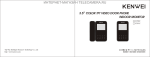
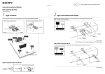
7” Two-wire Hand-Free Phone ¿ É Color Ê ÓVideo ¶ Door Ô ½ ² VDP-C37 Designs Subject to Change Without Prior Notice. INSTRUCTION MANUAL à BRIEF INTRODUCTION 4. It can call and communicate but monitor screen illuminates with Welcome to use our video security intercom system, this 2 -wire system is newl y released for villas or single houses. This products are based on CCTV technol ogies, you can watch over the outside conditions on indoor monitor no picture, the brightness and contrast control are not adjusted. . SPECIFICATIONS through the camera built in outdoor camera unit. The d ual-dir ectiona l speak er system and indoor lock-control function maximize safety by identify the visitors Switch Power Supply(SMPS) 100V befo re o peni ng d oor. E ven at d ark night, you can see the visitors clearly with Power Consumption Operation Chime Tones Dingdong/ 8 Chord Melody Rings infrared & white LEDs built in the camera. This product is of 2 wiring non-polarity technologies, it is much convenient and simple for installation and popularly used in homes, offices or businesses. Please read these instructions carefully before installing the system and follow all of 240V(50Hz/60Hz) 14W Standby 2W Audio Communication System Duplex Hand-Free Automatically Shutdown Time 60 Seconds Unlock Signal Output 12V/2A Wiring Cable between Monitor & Camera: 100ms <50m: 20AWG, 0.5mm2 the directions to ensure proper installation. This manual should be retained for future >50m: 18AWG, 1.0mm2 reference. Door Lock Wiring: 18AWG, 1.0mm2 Working Temperature -100C to +400C . ÌFEATURES ØÊ⹦ÄÜ: . STANDARD PARTS INDOOR MONITOR 1 2 3 5 6 12 11 7 8 4 9 10 1 Monitor and 1 Camera 1m Cable for Testing 13 14 Mounting Bracket for Monitor, 15 Camera & Screws User Manual Put the wired Camera Unit in the bracket, then attach a metal cover to the unit and OUTDOOR CAMERA fix with 4 self-tapping screws. 5 6 7 8 Cable Bracket 5 6 Metal Tab Camera Unit 1 2 1 2 3 3 4 4 ODS-J Metal Cover ODS-5 5 6 7 8 Screw Holes 7 8 5 6 7 8 . IMPORTANT NOTES 4 1. Do not install the monitor and camera units where they wi ll be exposed to direct 4 sunlight or other strong light and near to intense magnetic field. 2. Do turn off power of unit before cleaning. Do not use liquid or aerosol cleaners. Use a dry cloth for body of unit. ODS-S Micro phon e ODS-2 Camera 3. Disconnect the power if you do not use the product for a long time. Wiring Terminal to Monitor L1 Call Speaker Wiring Terminal to Monitor L2 4. Do not attempt to service this unit yourself as opening or removing covers may Lock Connector UNL+ Lock Connector UNL- expose you to dangerous voltage or other hazards. Refer all servicing to qualified service personnel. . TROUBLE SHOOTING GUIDE . OPERATION Indoor Monitor 1. Visitor Calling: A visitor presses the Call Button on the outdoor camera unit. The Carefully read and perform the following procedures before returning your video door phone for repairs of replacement. monitor's speaker will sound a chime tone to announce that a visitor is at the door and the visitor's image will be automatically displayed on the indoor monitor. 1. The unit totally dead(Power Lamp off), check the power plug if it is properly inserted Call Button into the AC outlet or the AC is not supplied. 2. Power Lamp is dim, the wires between the monitor and camera are shorted. 3. It can call and communicate but there is no audio signal, it is due to defective camera. Press Call Button Press Talk Button to Answer the Call 2. Talking: Press Talk Button and talk to the visitor. The visitor's image will remain 3 o n th e screen for 60 seconds or until you pressing the Talk Button again to finish ODS-S Dig a square hole which is the same size of the Flush Box in the wall and drill a talking. If there is no respond, the visitor's image will disappear from the monitor's hole in the center for wiring and 2 small holes for plug bolts. LCD screen within 60 seconds and return to standby mode. Fix the plug bolts in the 2 small holes and put the Flush Box into the wall and fix with 2 self-tapping screws. Hi John, here you are. Ok, I open the door for you now. Pull the wiring which connect to Monitor Unit through the central hole and connect well with Terminals L1&L2. Also prepare 2 wires to connect with Lock Connectors UNL+& UNL- and pull through Flush Box and central hole in the Hi John, here you are. Ok, I open the door for you now. wall and connect with the door lock. Waiting Outside Put the wired Camera Unit in the Flush Box and fix with 2 Hex Socket Cap Screws. Press Unlock Button to Release Door Lock 3. Warning: After speaking with the visitor, and if you have installed an electronic door locking system, you can press Unlock Button to ele ctro nica lly unlo ck t he d oor. I f you come into a bag guy or some one playing trick with you, you can keep pressing Warning Button for >2 seconds, the outdoor came ra's sp eake r wi ll s iren loudly to Put-in Cable scare away them. Driver for Hex Socket Cap Screws(Provided) Keep away from my house!! Flush Box Sirening 4 ODS-2 Drill a hole in the center area of the bracket just big enough for the electrical Press Warning Button Siren Outside 4. Monitoring: Press Monitor Button under standby mode, you will see the camera' s field of view for 60 seconds. And press Monitor Button again to close monitoring. wiring to pull through. And drill 7 small holes for the plug bolts. Insert and fix the plug bolts in the 7 small holes, then attach the mounting bracket and fix with 3 self-tapping screws(please note the 3rd screw is fixed with a Metal Tab). Pull the wiring which connect to Monitor Unit through the central hole and connect well with Terminals L1&L2. Also prepare 2 wires to connect with Lock Connectors UNL+& UNL- and pull through Bracket and central hole in the wall Press Monitor Button Outdoor View and connect with the door lock. “UNL+& UNL-” and pull through Bracket and central hole in the wall and connect 5. Others: 1) Effect Adjusting: Use the slide switch for Volume, Brightness & Contrast with the door lock. controls to get best effect you want. 2) Optional Chime Tones: Press Talk But ton Put the wired Camera Unit in the bracket and pop out the tab at the bottom of the under standby mode till the tone automatically sounds(about 5 seconds), then press unit. Fix it with drive screw and press back the tab. Warning Button to change tones(change with each pressing) till you find suitable tones, press Talk Button again to confirm and set it. B ra c k e t C ab le P u t - in Drive Screw Press Talk Button for 5s Tone Sound Automatically. Self-Tapping Screws Press Warning Button to Change Tone. Pop-out Tab 2 3) When come to expandable system, press Intercom Button under standby mode to call ODS-5 the other monitors and a “DuDu” tone is heard at the other monitors' speakers, and press Talk Dig a square hole which is the same size of the Flush Box in the wall and drill Button to talk. a hole in the center for wiring and 4 small holes for plug bolts. Fix the plug bolts in the 4 small holes and put the Flush Box into the wall and fix with 4 self-tapping screws. Bedroom Intercom & Interphone Pull the wiring which connect to Monitor Unit through the central hole and connect Living Room well with Terminals L1&L2. Also prepare 2 wires to connect with Lock Connectors UNL+& UNL- and pull through Flush Box and central hole in the wall and connect with the door lock. Put the wired Camera Unit in the Flush Box and fix with 4 drive screws. Outdoor Camera 1. While a visitor presses Call Button, a call tone is heard which verifies the call was placed. 2. The host press Talk Button, then intercom with the visitor through microphones. 3. The unit is built in infrared & white LEDs, you can see the visitors clearly even at deep night. Put-in Cable Flush Box rew e Sc v i r D s 4) Connect well the wires from Wiring Terminal and pull through the central hole . INSTALLATION which connect to the camera unit. . Attach the wired monitor unit to the bracket by setting the monitor over the four 5) 1.Wiring Diagram bracket hooks and sliding it down. Cable L1 L1 L2 L1 L2 L2 S1 S1 S2 S2 S1 L1 L2 U NL+ U NL- S2 Outdoor Camera Plug Bolt Door Lock Master Indoor Monitor Slave Indoor Monitor Bracket Self-Tapping Screws Hook Holes Slave Indoor Monitor 3. Camera Unit Notes: 1) For expandable system, please make sure it is master indoor monitor rather The monitor is compatible with several camera units (ODS-J/ODS-5/ODS-S than slave indoor monitor to co nnect with outdoor came ra. There is always 1 /ODS-2 are optional.), please verify the model no. before installation and follow master indoor monitor only in a system, the oth er slav e indoor monitors should correct directions. The recommended location of camera unit is at the height be connected from the master indoor monitor. 150~170cm from central part of Camera to the floor(for reference only). 2) This system is of 2-wire non-polarity technologies. The connection of terminals Notes: Do not expose the camera unit to direct can ignore their “+/-”polarity. monitor. Maximum 1 camera can expand to work with 3 monitors. 2.Monitor Unit 1) Select a mounting location to an AC outlet but the monitor cannot be exposed to dirt, direct sunlight(or other strong light), direct moisture conditions. After determining the location, attached mounting bracket securely to the wall. 2) Drill a hole in the center area of the bracket just big enough for the electrical wiring to pull through. And drill 4 small holes for plug bolts. 3) Insert and fix the plug bolts in the 4 small holes, then at tach the mounting bracket to the wall and fix with 4 self-tapping screws. 1.5-1.7m 3) The above figure in dotted line illustrates the standard system, that is 1 camera & 1 sunlight and be sure it is shield from storm rain. The background of visitors may be affected by street lamp and other strong light, you can mount some lamps to highlight for clearer images of visitors. 1) ODS-J Drill a hole in the center area of the bracket just big enough for the electrical wiring to pull through. And drill 2 small holes for the plug bolts. Insert and fix the plug bolts in the 2 small holes, then attach the mounting bracket to the wall and fix with 2 self-tapping screws. Pull the wiring which connect to Monitor Unit through the central hole and connect well with Terminals L1&L2. Also prepare 2 wires to connect with Lock Connectors