1
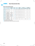
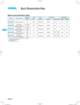
Basic Characteristics Data
Basic Characteristics Data
Rated
input fuse
Inrush
current
protection
Material
Single ended forward converter 570 - 670
*1
-
-
glass fabric base,epoxy resin
Multilayer
Yes
Yes
SFS15
Single ended forward converter 570 - 670
SFCS15
*1
-
-
glass fabric base,epoxy resin
Multilayer
Yes
Yes
SFS20
Single ended forward converter 570 - 670
*1
-
-
glass fabric base,epoxy resin
Multilayer
Yes
Yes
SFS30
Single ended forward converter 440 - 530
SFCS30
*1
-
-
glass fabric base,epoxy resin
Multilayer
Yes
Yes
SFS10
Circuit method
Switching
frequency
[kHz]
Series/Parallel
operation availability
Double Series Parallel
sided operation operation
Input
current
[A]
Model
PCB/Pattern
Single
sided
*1 Refer to Specification.
SFS/SFCS
SFS/SFCS
SFS/SFCS-14
SFS/SFCS-14
SFS_SFCS_E.indd 14
15.6.18 5:52:35 PM
DC-DC Converters PCB Mount Type Instruction Manual
1
Pin Configuration
SFS/SFCS-16
2
Connection for Standard Use
SFS/SFCS-16
3
Wiring Input / Output Pin
SFS/SFCS-16
3.1
Wiring input pin
SFS/SFCS-16
3.2
Wiring output pin
SFS/SFCS-17
4
Function
SFS/SFCS-18
4.1
Overcurrent protection (OCP) and Low voltage protection (LVP)
SFS/SFCS-18
4.2
Overvoltage protection (OVP)
SFS/SFCS-18
4.3
Remote ON / OFF (RC pin)
SFS/SFCS-18
4.4
Alarm (ALM pin)
SFS/SFCS-18
4.5
Start in / out (PO pin)
SFS/SFCS-19
4.6
Sequence
SFS/SFCS-19
4.7
Isolation
SFS/SFCS-19
5
Series and Parallel Operation
SFS/SFCS-19
5.1
Series operation
SFS/SFCS-19
5.2
Parallel operation
SFS/SFCS-20
6
Implementation-Mounting Method
SFS/SFCS-20
6.1
Automatic mounting
SFS/SFCS-20
6.2
Soldering temperature
SFS/SFCS-20
6.3
Cleaning
SFS/SFCS-20
6.4
Mounting method
SFS/SFCS-21
6.5
Storage method
SFS/SFCS-21
6.6
Stress to the product
SFS/SFCS-21
7
Safety Considerations
SFS/SFCS-21
8
Derating
SFS/SFCS-21
8.1
Derating curve (SFS1048, SFS1548)
SFS/SFCS-21
8.2
Derating curve (SFS1524, SFCS15)
SFS/SFCS-22
8.3
Derating curve (SFS2048)
SFS/SFCS-22
8.4
Derating curve (SFS3024, SFCS30)
SFS/SFCS-22
8.5
Derating curve (SFS3048)
SFS/SFCS-23
9
SMD type Package Information
SFS/SFCS-25
9.1
Delivery package information (SFS series SMD type)
SFS/SFCS-25
9.2
Delivery package information (SFCS series SMD type)
SFS/SFCS-25
SFS/SFCS-15
SFS/SFCS
DC-DC Converters PCB Mount Type
1 Pin Configuration
¿SFS10 / SFS15 / SFS20 / SFCS15
1pin mark (only applicable for SFS)
©
ƒ
´
1
2
3
4
5
6
2 Connection for Standard Use
¡In order to use the power supply, it is necessary to wire as shown
in Fig.2.1.
+Vin
+Vout
DC
Input
Load
ç
-Vin
-Vout
Fuse
å
0
9
8
7
SFS/SFCS
Instruction Manual
SW
PO
RC
Fig.1.1 Pin configuration (SFS10 / SFS15 / SFS20 / SFCS15)
ALM
¿SFS30 / SFCS30
Fig.2.1 Connection for standard use
1pin mark (only applicable for SFS)
©
ƒ
´
1
2
3
4
5
6
ç
å
0
9
8
7
¡When remote ON / OFF function is not used, please open RC pin
or short between RC and -Vin pin.
¡When alarm function is not used, please open ALM pin.
¡In parallel and series operation, connect each PO pin mutually.
When PO function is not used, please open PO pin.
¡The SFS / SFCS series handles only the DC input.
Avoid applying AC input directly.
!! It will damage the power supply. !!
¡Operate with the convection or forced air cooling.
[ Reference : 8 “Derating” ]
Fig.1.2 Pin configuration (SFS30 / SFCS30)
Table 1.1 Pin configuration and function
No.
1
2
3
4
5
6
7
8
9
0
å
ç
´
ƒ
©
Pin Name
NC(SMD)
Stopper(DIP)
+Vout
+Vout
+Vout
-Vout
-Vout
NC(SMD)
Stopper(DIP)
NC(SMD)
NC(DIP)
ALM
RC
PO
NC(SMD)
Stopper(DIP)
+Vin
+Vin
-Vin
-Vin
NC(SMD)
NC(DIP)
Case connecting pin
SFS/SFCS-16
Function
Not connected / Adhesive dispensing
Stopper
+DC output
+DC output
+DC output
-DC output
-DC output
Not connected / Adhesive dispensing
Stopper
Not connected / Adhesive dispensing
Not connected
Alarm
Remote ON / OFF
Start in / out
Not connected
Stopper
+DC input
+DC input
-DC input
-DC input
Not connected / Adhesive dispensing
Not connected
Isolated from internal circuit
Only applicable for SFCS type C (DIP)
3 Wiring Input/Output Pin
3.1 Wiring input pin
(1) External fuse
¡The SFS / SFCS series is not internally fused. To ensure safe operation and to receive each Safety Standards approvals, please
install an external fuse (fast-blow type).
¡When the input voltage from a front end unit is supplied to multiple
units, install a fast-blow type fuse in each unit.
¡Fuse must be connected to the +Vin side if to -Vin side is used as
ground, or fuse must be connected to -Vin side if +Vin side is used
as a ground.
Table 3.1 Recommended fuse (fast-blow type)
Model
Rated current
Model
Rated current
SFS1524 / SFCS1524
SFS3024 / SFCS3024
2A
4A
SFS1048/SFS1548/SFCS1548 SFS2048/SFS3048/SFCS3048
1A
2A
Instruction Manual
DC-DC Converters PCB Mount Type
(2) External capacitor on the input side
¡When the distance from the DC line to the unit is greatly extended,
it makes the input feedback noise much higher and the input volt-
Vin=48V
age several times higher than the normal level when turned ON. If
+Vin
1
DC
Input
100
1
+Vout
SFS30483R3
F
-Vin
Temp=25C
this happens, the output power also becomes unstable. In order to
80
prevent the unit form failing in this way; please connect Ci to the
the input pin.
The unit is powered from
high impedance source
L
CISPR22-A (QP)
Level [dB V]
input pin. In addition, when the filter with “L” is used, please Ci to
Load
-Vout
Fuse
90
Io=9A
H
70
CISPR22-A (Ave.)
60
50
40
+Vin
30
DC
Input
Ci
150k 200k 300k
500k
2M
3M
5M
10M
20M
30M
Frequency [Hz]
-Vin
Fig.3.3 Example of conducted noise (SFS30483R3)
(a)
(4) Reverse input voltage protection
+Vin
DC
Input
1M
¡Avoid the reverse polarity input voltage. It will damage the unit.
It is possible to protect the unit from the reverse input voltage by
Ci
installing an external diode as shown in Fig.3.4.
-Vin
+Vin
Long input line
DC
Input
(b)
-Vin
Fig.3.1 Connection method of capacitor at input pin
Fig.3.4 Reverse input voltage protection
Table 3.2 Recommended capacitance Ci
Model
SFS1524 / SFCS1524
SFS3024/SFCS3024
Ci
33 F
68 F
Model
SFS1048/SFS1548/SFS2048/SFCS1548 SFS3048/SFCS3048
Ci
10 F
22 F
Ta=-20 to +85C Electrolytic or Ceramic capacitor
3.2 Wiring output pin
¡When the SFS / SFCS series supplies the pulse current for the
pulse load, please install capacitor Co between +Vout and -Vout
pins.
+Vout
Ta=-40 to +85C Ceramic capacitor
Co
Note:
When input line inductance becomes excessively high due to insertion of choke coil, operation of the unit could become unstable. In
this case, increase Ci value more than the value indicated above.
Pulse
load
-Vout
Recommended capacitance (Co)
1.2 - 5Vout : 22 - 4700 F
10 - 15Vout : 22 - 2200 F
(3) Conducted noise
¡Install an external input filter as shown in Fig.3.2 in order to reduce conducted noise.
The result for this solution is shown in Fig.3.3.
L1
Fig.3.5 Connection for pulse load
¡Output ripple and start-up waveform may be influenced by ESRESL of capacitor and the wiring impedance.
+Vin
DC
Input
C1
-Vin
Fuse
C1 : 1 F(ceramic capacitor)
L1 : 1 H
Fig.3.2 Recommended external input filter
SFS/SFCS-17
SFS/SFCS
Instruction Manual
DC-DC Converters PCB Mount Type
¡Ripple and ripple noise are measured, as shown in the Fig.3.6, by
connecting Co and JEITA attachment.
+Vin
+Vout
(1) RC connection example 1
¡Remote ON / OFF connection and specification refer to below.
1.2 - 5Vout : Co=22 F
10 - 15Vout : Co=0.1 F
+Vin
SW
Co
DC
Input
-Vin
Load
+Vin
VRC1
DC
Input
VRC1
DC
Input
RC
Photo coupler RC
-Vout
25mm
-Vin
Oscilloscope
Bw:100MHz
R
1. 5m 50W
Coaxial Cable
C
JEITA attachment
R =50W
C =4700pF or 10000pF
Table 4.1 Specification of example 1 (connection method Fig.4.1 (a), (b))
Between RC and +Vin (VRC1)
Output voltage
Open
ON
0V[VRC1[1.2V or Short
OFF
Fig.3.6 Measuring method of ripple and ripple noise
SFS/SFCS
4 Function
-Vin
(a)
(b)
Fig.4.1 RC connection example 1
(2) RC connection example 2
+Vin
+Vin
R1
R1
4.1 Overcurrent protection (OCP) and Low
voltage protection (LVP)
RC
DC
Input
R2
SW
signal for at least 1 second.
4.2 Overvoltage protection (OVP)
¡The overvoltage protection circuit is built-in and comes into effect
at 120% to 140% (SFS20 : 115% to 145%) of the rated output voltage. When the load factor is less than 50%, output voltage may
be increased more than maximum voltage by the failure mode.
¡Normal or abnormal operation of the unit can be monitored by using the ALM pin. When OVP is activated, ALM signal will become
low level.
¡The DC input should be shut down if overvoltage protection is in
operation.
¡Please note that devices inside the power supply might fail when
voltage more than rated output voltage is applied to output pin of
the power supply. This could happen when the customer tests the
overvoltage performance of the unit.
4.3 Remote ON / OFF (RC pin)
¡Remote ON / OFF circuits is built-in on input side.
¡When remote ON / OFF function is not use, please open-circuit
between RC and +Vin or short-circuit between RC and -Vin.
VRC2
Transistor
-Vin
-Vin
(a)
max (SFS20 : 95% max) of the rated output voltage.
or less input for at least 1 second, or toggling remote ON / OFF
R2
VRC2
¡OCP and LVP circuits is built-in. LVP will trigger after 200ms typ
delay when OCP activates and output voltage drops down 90%
¡When LVP is activated, ALM signal will becomes low impedance.
¡Recovery from the protection is accomplished by applying 5VDC
RC
DC
Input
(b)
Recommended value of R1
Model
R1
SFSO24 SFSO48
SFCSO24 SFCSO48
22kW
220kW
Value of R2
Model
R2
200kW
360kW
Table 4.2 Specification of example 2 (connection method Fig.4.2 (a), (b))
Between RC and –Vin (VRC2)
Output voltage
10V or more (SFSO24 / SFCSO24)
20V or more (SFSO48 / SFCSO48)
or Open
OFF
0V[VRC2[1.2V or Short
ON
4.4 Alarm (ALM pin)
¡Normal or abnormal operation of the unit can be monitored by using the ALM pin.
¡When OVP or LVP are activated, ALM pin becomes same level as
-Vin pin.
¡The sink current of ALM pin is 10mA max.
Sink current
10mA(max) ALM
-Vin
Fig.4.3 ALM circuit
SFS/SFCS-18
SFCSO24 SFCSO48
Fig.4.2 RC connection example 2
¡Recovery from the protection is accomplished by applying 5VDC
or less input for at least 1 second, or toggling remote ON / OFF
signal for at least 1 second.
SFSO24 SFSO48
8V(typ)
DC-DC Converters PCB Mount Type
¡By connecting ALM pin in parallel and series operation, when one
unit has shut down by overvoltage protection or low voltage protection, other units will be shut down.
Instruction Manual
5 Series and Parallel Operation
¡When alarm function is not use, please open ALM pin.
¡Total number of units should be no more than 20 pieces.
5.1 Series operation
4.5 Start in / out (PO pin)
¡In series operation, connect each PO and ALM pin mutually, wiring
as Fig.5.1.
¡By connecting PO pin, difference of start-up voltage and stop voltage can be prevented.
¡In parallel and series operation, please connect each PO pin mutually.
+Vout
-Vin
-Vout
Fuse
SW
¡Total number of units should be no more than 20 pieces.
PO
RC
LED
Load
ALM
4.6 Sequence
¡The sequence time chart of Vin, Vout, PO, ALM and RC pins is
shown in Fig.4.4.
20-200ms
+Vin
DC
input
200ms(typ)
Fuse
+Vin
+Vout
-Vin
-Vout
SFS/SFCS
PO
Vin
RC
start-up
detection
ALM
OCP set
Vout
(a) Connection 1
start-up
remote ON
LVP set
PO
+Vin
+Vout
-Vin
-Vout
Load
+Vin
+Vout
Load
-Vin
-Vout
DC
input
Fuse
ALM
SW
ALM set
ALM reset
LED
PO
RC
ALM
RC
OFF
ON
Fig.4.4 Sequence time chart
Fuse
4.7 Isolation
¡For a receiving inspection, such as Hi-Pot test, gradually increase
(decrease) the voltage for a start (shut down).
Avoid using Hi-Pot tester with the timer because it may generate
voltage a few times higher than the applied voltage, at ON / OFF
of a timer.
PO
RC
ALM
(b) Connection 2
Fig.5.1 Examples of series operation
SFS/SFCS-19
DC-DC Converters PCB Mount Type
5.2 Parallel operation
Instruction Manual
ALM
¡In parallel operation, connect each PO and ALM pin mutually, wiring as Fig.5.2.
¡To improve the load sharing of each unit, please use the same
length from each unit to the load.
+Vout
¡Total number of units should be no more than 10 pieces.
+Vin
+Vout
-Vin
-Vout
DC
Input
Load
Fuse
SW
LED
Fig.6.1 Measuring point
PO
RC
(C)
ALM
+Vin
+Vout
-Vin
-Vout
SFS/SFCS
Tp
Tx
Fuse
PO
RC
Ty2
ALM
Ty1
Fig.5.2 Example of parallel operation
A
A’
B
B’
6 Implementation-Mounting Method
6.1 Automatic mounting
¡SFS / SFCS series is designed to have a large flat area in the
center of the top surface to serve as a pick up point for automated
vacuum pick and place equipment.
¡An excessively low bottom dead point of the suction nozzle imposes great force on the core of SFS series during mounting, causing
cracked core. So during mounting, take enough care.
6.2 Soldering temperature
time(s)
A
A’
B
B’
C
to reflow condition.
¡Improper reflow condition may degrade the reliability of the internal components.
¡While soldering, having vibration or impact on the unit should be
avoided, because of solder melting.
1.0 - 5.0C/ s
Ty1 : 160 10C
Ty2 : 180 10C
Ty1 - Ty2 : 120s max
1.0 - 5.0C/ s
Tp : Max245C 10s max
Tx : 220C or more : 70s max
1.0 - 5.0C/ s
Fig.6.2 Recommeded reflow condition of soldering
(Temperature of the pins)
(1) Reflow soldering
¡Fig.6.1 and 6.2 show the conditions of reflow soldering.
Please verify the temperature of the ALM pin and +Vout pin satisfy
C
(2) Flow soldering
¡260C, less than 15 seconds.
(3) Soldering iron
¡340C to 360C, less than 5 seconds.
6.3 Cleaning
¡When cleaning is necessary, follow the undermentioned condition.
Method: Varnishing, ultrasonic wave and vapor
Cleaning agents: IPA (Solvent type)
Total time: 2 minutes or less
¡After cleaning, dry them enough.
SFS/SFCS-20
Instruction Manual
DC-DC Converters PCB Mount Type
6.4 Mounting method
8 Derating
¡Avoid placing pattern layout in hatched area in Fig.6.3 to insulate
between pattern and power supply.
¡It is necessary to note thermal fatigue life by power cycle.
Please reduce the temperature fluctuation range as much as pos-
38.7
36.7
sible when the up and down of temperature are frequently gener-
2
ated.
©
1
8.1 Derating curve (SFS1048, SFS1548)
Out line
(1) Single and series operation
7
8
*Top view
*Dimensions in mm
Fig.6.3 Prohibition area of pattern lay out
Load factor [%]
100
6.5 Storage method
used within a year.
¡24-hours-baking is recommended at 125C, if unpacked products
was kept under uncontrol condition, in which 30C, 60%RH or
higher.
Original tray is not heat-resistant, please move them to heat-
50
SFS/SFCS
0
- 20
20
40
80 (85)
60
100
Ambient temperature [C]
100
resistant tray preparing to bake them.
SFS154815
80
Others
Vin=60 - 76V
Convection (0.2m/s)
50
0
- 40
To check moisture condition in the pack, silica gel packet has
0
- 20
20
40
(75) 80
60
100
Ambient temperature [C]
some moisture condition indicator particle.
Fig.8.1 Derating curve
Indicated blue means good. Pink means alarm to bake it.
¡Notification. the tray will be deformed and the power supply might
be damaged, if the vacuum pressure is too much to reseal.
Others
Vin=36 - 60V
Convection (0.2m/s)
0
- 40
Load factor [%]
¡To stock unpacked products in your inventory, it is recommended
to be kept under controlled condition, 5-30C, 60%RH and be
SFS154815
80
(2) Parallel operation
6.6 Stress to the product
¡SFS/SFCS series transformer core and choke coil core are attached by glue, and there is a cover over the core, which is attached by a clasp.
Load factor [%]
100
There is a possibility that the core will be removed and power sup-
Others
Vin=36 - 60V
Convection (0.2m/s)
50
0
- 40
ply will be damaged when it took stress by the fall or some kind of
SFS154815
80
- 20
0
20
40
60
(75) 80
100
Ambient temperature [C]
stress.
7 Safety Considerations
¡To apply for safety standard approval using this power supply, the
following conditions must be met.
Load factor [%]
100
SFS154815
80
Others
Vin=60 - 76V
Convection (0.2m/s)
50
0
- 40
- 20
0
20
40
60
(70) (75)80
100
Ambient temperature [C]
¿This unit must be used as a component of the end-use equipment.
¿The equipment does neither contain any basic nor double / rein-
Fig.8.2 Derating curve (Parallel operation)
forced insulation between input and output.
If the input voltage is greater than 60VDC, this has to be provided
by the end-use equipment according to the final build in condition.
¿Safety approved fuse must be externally installed on input side.
SFS/SFCS-21
DC-DC Converters PCB Mount Type
3Forced air cooling (1.2m/s)
8.2 Derating curve (SFS1524, SFCS15)
100
(1) Single and series operation
Convection (0.2m/s)
50
Vin=36 - 60V
80
70
Load factor [%]
Load factor [%]
100
Vin=60 - 76V
Forced air (1.2m/s)
50
0
- 40
0
- 40
Instruction Manual
- 20
0
20
40
60
(75) 80 (85)
100
Ambient temperature [C]
0
- 20
20
40
60
(75)
80 (85)
100
Fig.8.7 Derating curve (Forced air 1.2m/s)
Ambient temperature [C]
Fig.8.3 Derating curve
8.4 Derating curve (SFS3024, SFCS30)
(2) Parallel operation
(1) Single and series operation
1Natural convection cooling (0.2m/s)
100
Convection (0.2m/s)
50
0
- 40
- 20
0
20
40
60
80
100
Ambient temperature [C]
Load factor [%]
Load factor [%]
100
65%
Convection (0.2m/s)
50
0
- 40
Fig.8.4 Derating curve (Parallel operation)
- 20
0
20
40
80 (85)
100
(75) 80 (85)
100
60
Ambient temperature [C]
8.3 Derating curve (SFS2048)
Fig.8.8 Derating curve (Convection)
(1) Single, series and parallel operation
1Natural convection cooling (0.2m/s)
2Forced air cooling (0.8m/s)
Vin=60 - 76V
Vin=36 - 60V
60
50
0
- 40
Convection (0.2m/s)
- 20
0
20
40
60 (65)
80 (85)
100
Load factor [%]
Load factor [%]
100
Forced air (0.8m/s)
50
0
- 40
100
- 20
0
Ambient temperature [C]
Vin=36 - 60V
Forced air (0.8m/s)
0
20
40
60 (65)
80 (85)
Ambient temperature [C]
Fig.8.6 Derating curve (Forced air 0.8m/s)
SFS/SFCS-22
100
100
Load factor [%]
Vin=60 - 76V
- 20
60
3Forced air cooling (1.2m/s)
100
0
- 40
40
Fig.8.9 Derating curve (Forced air 0.8m/s)
2Forced air cooling (0.8m/s)
70
60
50
20
Ambient temperature [C]
Fig.8.5 Derating curve (Convection)
Load factor [%]
SFS/SFCS
Forced air (1.2m/s)
50
0
- 40
- 20
0
20
40
60
80 (85)
Ambient temperature [C]
Fig.8.10 Derating curve (Forced air 1.2m/s)
100
DC-DC Converters PCB Mount Type
(2) Parallel operation
1Natural convection cooling (0.2m/s)
8.5 Derating curve (SFS3048)
(1) Single and series operation
1Natural convection cooling (0.2m/s)
100
100
65%
SFS30481R8
Convection (0.2m/s)
Load factor [%]
Load factor [%]
Instruction Manual
50
0
- 40
- 20
0
20
40
60 (65)
80
Vin=36 - 60V
Convection (0.2m/s)
50
0
- 40
- 20
0
Fig.8.11 Derating curve (Convection)
60%
20
40
60
(75) 80 (85)
100
Ambient temperature [C]
100
Load factor [%]
2Forced air cooling (0.8m/s)
100
Load factor [%]
85%
75%
SFS30483R3
SFS304805
SFS304810
SFS304812
SFS304815
100
Ambient temperature [C]
SFS30481R2
SFS30481R5
SFS304802
SFS30482R5
Forced air (0.8m/s)
50
Vin=60 - 76V
Convection (0.2m/s)
50
0
- 40
SFS30481R8
SFS30481R2
SFS30481R5
SFS304802
SFS30482R5
75%
60%
SFS30483R3
SFS304805
SFS304810
SFS304812
SFS304815
- 20
0
20
40
60(65)
SFS/SFCS
55%
(75) 80 (85)
100
Ambient temperature [C]
0
- 40
- 20
0
20
40
60
80 (85)
100
Fig.8.14 Derating curve (Convection)
Ambient temperature [C]
2Forced air cooling (0.8m/s)
Fig.8.12 Derating curve (Forced air 0.8m/s)
100
Load factor [%]
3Forced air cooling (1.2m/s)
Forced air (1.2m/s)
Vin=36 - 60V
Forced air (0.8m/s)
50
50
0
- 40
- 20
0
20
40
60
80 (85)
100
Ambient temperature [C]
- 20
0
20
40
60
(75) 80 (85)
100
100
Ambient temperature [C]
Fig.8.13 Derating curve (Forced air 1.2m/s)
Load factor [%]
0
- 40
SFS30481R8
Vin=60 - 76V
Forced air (0.8m/s)
80%
Others
50
0
- 40
- 20
0
20
40
60
80 (85)
100
Ambient temperature [C]
Fig.8.15 Derating curve (Forced air 0.8m/s)
3Forced air cooling (1.2m/s)
100
Load factor [%]
Load factor [%]
100
Vin=36 - 76V
Forced air (1.2m/s)
50
0
- 40
- 20
0
20
40
60
80 (85)
100
Ambient temperature [C]
Fig.8.16 Derating curve (Forced air 1.2m/s)
SFS/SFCS-23
DC-DC Converters PCB Mount Type
(2) Parallel operation
1Natural convection cooling (0.2m/s)
(3) Measuring point in forced air cooling
SFS30481R8
Load factor [%]
100
Vin=36 - 60V
Convection (0.2m/s)
50
0
- 40
Instruction Manual
SFS30481R2
SFS30481R5
SFS304802
SFS30482R5
¡In case of forced air, ventilation must keep the temperature of
point A and B below 120C. Refer to Fig.8.20 for the location of
point A and B.
85%
75%
60%
SFS30483R3
SFS304805
SFS304810
SFS304812
SFS304815
- 20
0
20
40
60
(75) 80 (85)
100
Ambient temperature [C]
SFS30481R8
Vin=60 - 76V
Convection (0.2m/s)
50
0
- 40
SFS30481R2
SFS30481R5
SFS304802
SFS30482R5
60%
SFS30483R3
SFS304805
SFS304810
SFS304812
SFS304815
- 20
0
20
40
60 (65)
Point A
75%
Fig.8.20 Location of point A and B
(75) 80 (85)
100
Ambient temperature [C]
2Forced air cooling (0.8m/s)
Load factor [%]
100
85%
SFS30481R8
Vin=36 - 60V
Forced air (0.8m/s)
Others
50
0
- 40
- 20
0
20
40
60
80 (85)
100
Ambient temperature [C]
Load factor [%]
100
85%
SFS30481R8
70%
Vin=60 - 76V
Forced air (0.8m/s)
Others
50
0
- 40
- 20
0
20
40
60
(75)80 (85)
100
Ambient temperature [C]
Fig.8.18 Derating curve (Forced air 0.8m/s)
3Forced air cooling (1.2m/s)
Load factor [%]
100
Vin=36 - 60V
Forced air (1.2m/s)
50
0
- 40
- 20
0
20
40
60
80 (85)
100
Ambient temperature [C]
100
85%
SFS30481R8
Vin=60 - 76V
Forced air (1.2m/s)
Others
50
0
- 40
- 20
0
20
40
60
(75)80 (85)
Ambient temperature [C]
Fig.8.19 Derating curve (Forced air 1.2m/s)
SFS/SFCS-24
Point B
55%
Fig.8.17 Derating curve (Convection)
Load factor [%]
SFS/SFCS
Load factor [%]
100
100
DC-DC Converters PCB Mount Type
9 SMD type Package Information
Instruction Manual
¡Tray is stacked with alternating opposite direction to prevent products from contacting against the bottom of trays.
Do not cut or deform the tray.
9.1 Delivery package information (SFS series
SMD type)
¡These are packed in a tray (Fig.9.1, 9.2).
¡Capacity of the tray is 15 max.
In case of fractions, the units are stored in numerical order.
250
40X4=160
9.3
13
14
15
10
11
12
7
8
9
4
5
6
2
3
SFS/SFCS
Fig.9.3 Stacking pattern of trays
45
9.2 Delivery package information (SFCS series
SMD type)
45
¡These are packed in a tray (Fig.9.4).
SFCS15 and SFCS30 can be used in the same pallet tray.
55X2=110
200
But the orientation of the power supplies is different.
¡Capacity of the tray is 10 max.
In case of fractions, the units are stored in numerical order.
Dimension in mm
¡Do not cut or deform the tray.
Material : Conductive PS
14
15
10
11
12
7
8
9
4
5
6
2
3
322.6
60.4X4=241.6
13
2
7
3
8
4
9
5
10
IN
44.6
250
40.2X4=160.8
SFCS15XXXX
IN
OUT
OUT
40.5
12
135.9
57.2
39.35
SFCS30XXXX
Fig.9.1 Delivery package information(SFS10/SFS15/SFS20)
49.6
50.4X2=100.8
200
16.6
Dimension in mm
Dimension in mm
Material : Conductive PS
Material : Conductive PS
Fig.9.2 Delivery package information(SFS30)
Fig.9.4 Delivery package information(SFCS15/SFCS30)
SFS/SFCS-25