1
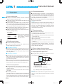
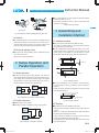
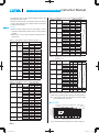
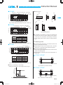
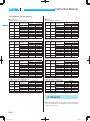
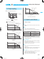
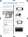
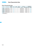
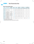
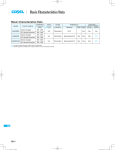
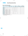
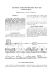
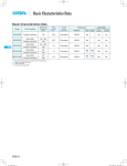
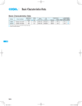
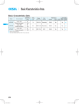
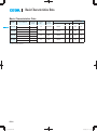
Basic Characteristics Data
Basic Characteristics Data
Model
LFP
LFP100F
LFP150F
LFP240F
LFP300F
Circuit method
Switching
frequency
[kHz]
Active filter
60
Forward converter
130
Active filter
60
Forward converter
130
Active filter
60
Forward converter
130
Active filter
60
Forward converter
140
*1 The value of input current is at ACIN 100V and rated load.
*2 Refer to Instruction Manual 2.
LFP-10
Inrush
current
protection
Material
1.3
Thermistor
2.0
Input
current
*1 [A]
Series/Parallel
operation availability
PCB/Pattern
Single
sided
*2
Double
sided
Series
operation
Parallel
operation
CEM-3
Yes
Yes
No
Thermistor
CEM-3
Yes
Yes
No
3.6
SCR
CEM-3
Yes
Yes
No
4.3
SCR
CEM-3
Yes
Yes
No
AC-DC Power Supplies Open Frame/ Enclosed Type Instruction Manual
1
2
3
Function
LFP-12
1.1
Input voltage range
LFP-12
1.2
Inrush current limiting
LFP-12
1.3
Overcurrent protection
LFP-12
1.4
Overvoltage protection
LFP-12
1.5
Thermal protection
LFP-12
1.6
Output voltage adjustment range
LFP-12
1.7
Output ripple and ripple noise
LFP-12
1.8
Isolation
LFP-13
1.9
Reducing standby power
LFP-13
Series Operation and Parallel Operation
LFP-13
2.1
Series Operation
LFP-13
2.2
Parallel Operation
LFP-13
Assembling and Installation Method
LFP-13
3.1
Installation method
LFP-13
3.2
Derating
LFP-13
3.3
Mounting screw
LFP-15
3.4
Expectancy life and warranty
LFP-16
4
Ground
LFP-16
5
Peak loading
LFP-17
6
Option and Others
LFP-17
6.1
Outline of options
LFP-17
6.2
Others
LFP-19
LFP-11
LFP
AC-DC Power Supplies Open Frame/ Enclosed Type
1.4 Overvoltage protection
1 Function
LFP
Instruction Manual
¡An overvoltage protection circuit is built-in. If the overvoltage protection circuit is activated, shut down the input voltage, wait more
than 3 minutes and turn on the AC input again to recover the out-
1.1 Input voltage range
put voltage. Recovery time varies depending on such factors as
¡The range is from AC85V to AC264V or DC120V to DC370V
(please see SPECIFICATIONS for details).
¡In cases that conform with safety standard, input voltage range is
AC100-AC240V (50/60Hz).
input voltage value at the time of the operation.
¡In option -R2, overvoltage protection is removed by toggling ON/
OFF signal of remote control.
Remarks :
¡If input value doesn’t fall within above range, a unit may not operate in accordance with specifications and/or start hunting or fail.
Please avoid applying a voltage exceeding the rated voltage to an
If you need to apply a square waveform input voltage, which is
tion or fail. If you cannot avoid doing so, for example, if you need
commonly used in UPS and inverters, please contact us.
to operate a motor, etc., please install an external diode on the
¡When the input voltage changes suddenly, the output voltage accuracy might exceed the specification. Please contact us.
¡Operation stop voltage is set at a lower value than that of a standard version (derating is needed).
-Use Conditions
Output
LFP100F
LFP150F
LFP240F
LFP300F
30W
50W
80W
100W
*Please avoid using continuously
for more than 1 second under
above conditions. Doing so
may cause a failure.
Input AC50V or DC70V
Duty 1s/30s
1.2 Inrush current limiting
¡An inrush current limiting circuit is built-in.
¡If you need to use a switch on the input side, please select one
that can withstand an input inrush current.
¿ LFP100F, LFP150F
¡Thermistor is used in the inrush current limiting circuit. When you
turn the power ON/OFF repeatedly within a short period of time,
output terminal. Doing so may cause a power supply to malfunc-
output terminal to protect the unit.
1.5 Thermal protection
¡A thermal protection circuit is built-in.
The thermal protection circuit may be activated under the following conditions and shut down the output.
1When a temperature continue to exceed the values determined
by the derating curve.
2When a current exceeding the rated current is applied.
3When convection stops.
4When peak load is applied in conditions other than those shown
in Section 5.
If the thermal protection circuit is activated, shut off the input voltage and eliminate all the overheating conditions. To recover the
output voltage, have enough time to cool down the unit before
turning on the input voltage again.
1.6 Output voltage adjustment range
¡Adjustment of output voltage is possible by using potentiometer.
please have enough intervals so that a power supply cools down
before being turned on.
¿ LFP240F, LFP300F
¡Thyristor technique is used in the inrush current limiting circuit.
When you turn power ON/OFF repeatedly within a short period of
1.7 Output ripple and ripple noise
¡Output ripple noise may be influenced by measurement environment, measuring method fig.1.1 is recommended.
+Vout
time, please have enough intervals so that the inrush current limit-
C1
C2 +
ing circuit becomes operative.
¡When the switch of the input is turned on, the primary inrush current and secondary inrush current will be generated because the
-Vout
150mm
Osiloscope/
Ripple noise meter
Bw:20MHz
thyristor technique is used for the inrush current limiting circuit.
1.3 Overcurrent protection
¡An overcurrent protection circuit is built-in and activated at 101%
of the peak current. A unit automatically recovers when a fault
Load
Differential probe
C1 : Film capacitor 0.1μF
C2 : Aluminum electrolytic capacitor 22μF
condition is removed.
Please do not use a unit in short circuit and/or under an overcurrent condition.
¡Intermittent Operation Mode
Intermittent operation for overcurrent protection is included in a
Fig.1.1 Measuring method of Ripple and Ripple Noise
Remarks :
When GND cable of probe with flux of magnetic force from power
supply are crossing, ripple and ripple noise might not measure
part of series. When the overcurrent protection circuit is activated
correctly.
and the output voltage drops to a certain extent, the output be-
Please note the measuring environment.
comes intermittent so that the average current will also decrease.
LFP-12
AC-DC Power Supplies Open Frame/ Enclosed Type
Instruction Manual
¡Even a slight difference in output voltage can affect the balance
between the values of I1 and I2.
Please make sure that the value of I3 does not exceed the rated
current of a power supply.
I3 [ the rated current value
LFP
Bad example
Good example
Fig.1.2. Example of measuring output ripple and ripple noise
3 Assembling and
Installation Method
1.8 Isolation
¡For a receiving inspection, such as Hi-Pot test, gradually increase
(decrease) the voltage for the start (shut down). Avoid using HiPot tester with the timer because it may generate voltage a few
times higher than the applied voltage, at ON/OFF of a timer.
3.1 Installation method
¡This power supply is manufactured by SMD technology.
The stress to P.C.B like twisting or bending causes the defect of
the unit,so handle the unit with care.
¡In case of metal chassis, keep the distance between d1 & d2 for to
insulate between lead of component and metal chassis, use the
1.9 Reducing standby power
¡As for option -R2, reducing standby power is possible by OFF signal of the remote control.
spacer of 8mm or more between d1. If it is less than d1 & d2, insert
the insulation sheet between power supply and metal chassis.
Please refer to instruction manual 6.1.
d2
CN1
2 Series Operation and
Parallel Operation
d1 = 8mm min
d2
CN1
d2
d2
2.1 Series Operation
d2 = 4mm min
¡You can use a power supply in series operation. The output current in series operation should be lower than the rated current of a
d2
power supply with the lowest rated surrent among power supplies
Fig.3.1 Installation method
that are serially connected. Please make sure that no surrent ex-
¡There is a possibility that it is not possible to cool enough when
the power supply is used by the sealing up space as showing in
Load
Power +
Supply -
Power +
Supply -
Load
Power +
Supply -
Power +
Supply -
Figure 3.2.
Load
ceeding the rated current flows into a power supply.
B of Instruction Manual 3.2.
Please use it after confirming the temperature of point A and point
Case
Fig.2.1 Examples of connecting in series operation
Power supply
2.2 Parallel Operation
Fig.3.2 Installation example
¡Parallel operation is not possible.
¡Redundancy operation is available by wiring as shown below.
+
I1
I3
Power
Supply -
¡Environment to use it and Installation environment
When using it,it is necessary to radiate heat by the heat of the power supply.
Load
Power +
Supply -
3.2 Derating
I2
Table 3.1 - 3.4 shows the relation between the upper limit temperature (Point A and Point B) and load factors.
Please consider the ventilation so that the convection which is
enough for the whole power supply is provided.
And temperature of Point A and Point B please become lower than
Fig.2.2 Example of redundancy operation
upper limit temperature.
LFP-13
AC-DC Power Supplies Open Frame/ Enclosed Type
The expectancy life in the upper bound temperature (Point A and
Point B) is three years or more.
Please refer to External View for the position of Point A and Point B.
In case of with Chassis and Cover, please contact our sales office
potential.
*Please refer to 3.4 if you want to extend the longevity of the expectancy life.
Table 3.1 Temperatures of Point A, Point B LFP100F-O-Y
Cooling
Method
Load factor
75%<Io[100%
Convection 50%<Io[75%
0%<Io[50%
75%<Io[100%
Convection 50%<Io[75%
B
0%<Io[50%
75%<Io[100%
Convection 50%<Io[75%
C
0%<Io[50%
75%<Io[100%
Convection 50%<Io[75%
D
0%<Io[50%
75%<Io[100%
Convection 50%<Io[75%
E
0%<Io[50%
75%<Io[100%
Convection 50%<Io[75%
F
0%<Io[50%
70%<Io[100%
A,B,C,D,E,F Forced air
0%<Io[70%
A
Max temperature
Point A[C] Point B[C]
88
86
89
89
89
89
82
81
89
89
89
89
85
86
89
89
89
89
84
76
89
86
89
89
81
89
86
89
87
89
80
77
85
86
88
89
75
75
75
75
Table 3.2 Temperatures of Point A, Point B LFP150F-O-Y
Mounting
Cooling
Method
Method
Load factor
75%<Io[100%
Convection 50%<Io[75%
0%<Io[50%
75%<Io[100%
Convection 50%<Io[75%
B
0%<Io[50%
75%<Io[100%
Convection 50%<Io[75%
C
0%<Io[50%
75%<Io[100%
Convection 50%<Io[75%
D
0%<Io[50%
75%<Io[100%
Convection 50%<Io[75%
E
0%<Io[50%
75%<Io[100%
Convection 50%<Io[75%
F
0%<Io[50%
70%<Io[100%
A,B,C,D,E,F Forced air
0%<Io[70%
A
Mounting
Cooling
Method
Method
Load factor
75%<Io[100%
Convection 50%<Io[75%
0%<Io[50%
75%<Io[100%
Convection 50%<Io[75%
B
0%<Io[50%
75%<Io[100%
C
Convection 50%<Io[75%
0%<Io[50%
75%<Io[100%
D
Convection 50%<Io[75%
0%<Io[50%
75%<Io[100%
E
Convection 50%<Io[75%
0%<Io[50%
75%<Io[100%
Convection 50%<Io[75%
F
0%<Io[50%
70%<Io[100%
A,B,C,D,E,F Forced air
0%<Io[70%
Max temperature
Point A[C] Point B[C]
84
81
89
89
89
89
83
81
89
89
89
89
87
85
89
89
89
89
83
65
89
75
89
85
77
86
81
89
86
89
78
76
82
82
89
89
75
75
75
75
Max temperature
Point A[C] Point B[C] Point C[C]
89
82
89
88
89
89
85
74
89
82
89
89
89
83
89
88
89
89
88
74
89
85
89
89
89
86
89
89
89
89
79
68
86
77
89
89
75
75
85
75
75
85
Table 3.4 Temperatures of Point A, Point B, Point C, Point D
LFP300F-O-TY
Mounting
Cooling
Method
Method
Load factor
80%<Io[100%
Convection 60%<Io[80%
Io[60%
80%<Io[100%
B
Convection 60%<Io[80%
Io[60%
80%<Io[100%
Convection 60%<Io[80%
C
Io[60%
80%<Io[100%
Convection 60%<Io[80%
D
Io[60%
80%<Io[100%
Convection 60%<Io[80%
E
Io[60%
50%<Io[100%
A,B,C,D and E Forced air
Io[50%
A
Max temperature
Point A[C] Point B[C] Point C[C] Point D[C]
70
86
75
88
79
89
59
68
68
76
76
86
70
84
77
89
80
89
57
64
65
73
77
83
60
79
66
81
76
88
75
75
85
85
75
75
85
85
¡The operative ambient temperature is different by with / without
chassis cover or mounting position. Derating curve is shown below.
Note: In the hatched area, the specification of Ripple, Ripple
Noise is different from other area.
¿ LFP100F
1(A)mounting
1 (D), (E), (F) 1(C)mounting 1(B)mounting
mounting
2 (A) ~ (F)
mounting
100
Load factor [%]
Remarks:
*Please be careful of electric shock or earth leakage in case of
temperature measurement, because Point A and Point B is live
Mounting
Method
Table 3.3 Temperatures of Point A, Point B, Point C LFP240F-O-Y
A
for getting more information.
LFP
Instruction Manual
80
70
60
50
40
30
20
0
-10
1Convection
2Forced air
(0.5m3 / min)
0
10
20
30
35
40
45
50
60
70
Ambient temperature [C]
Fig.3.3 Ambient temperature derating curve (refer to Table 3.1)
LFP-14
Instruction Manual
AC-DC Power Supplies Open Frame/ Enclosed Type
¿ LFP150F
¡Mounting method
1(D), (E), (F)
mounting
1(C)mounting 1(B)mounting
1(A)mounting
Load factor [%]
80
70
60
50
40
30
20
0
-10
(A)
2 (A) ~ (F)
mounting
100
(B)
CN1
(C)
CN1
1Convection
2Forced air
(0.5m3 / min)
0
10
20
LFP
30
40
45
50
60
CN1
Standard
Position
70
Ambient temperature [C]
(D)
Fig.3.4 Ambient temperature derating curve (refer to Table 3.2)
(E)
(F)
CN1
¿ LFP240F
1 (D), (E)mounting 1 (C)mounting 1 (B)mounting
1 (A)mounting
1 (F)mounting
2 (A) ~ (F)
mounting
Load factor [%]
100
80
70
60
1Convection
2Forced air
(0.5m3 / min)
40
30
20
0
-10
CN1
CN1
Fig.3.8 Mounting method
0
10
20
25 30
35 40
45
50
60
70
¡(F) of LFP300F is not possible. (F) mounting is not possible when
unit is with case cover, but if need to operate unit by (F) position-
Ambient temperature [C]
Output power[W]
1Convection
2Forced air
240.0
300.0
240.0
300.0
241.2
302.4
240.0
302.4
Output
voltage
24V
30V
36V
48V
ing with case cover, temperature / load derating is necessary.
For more details, please contact our sales or engineering departments.
3.3 Mounting screw
Fig.3.5 Ambient temperature derating curve (refer to Table 3.3)
¿ LFP300F
1 (D), (E)mounting
1 (B), (C)mounting
1 (A)mounting
2 (A) ~ (E)
mounting
Load factor [%]
100
80
1Convection
2Forced air
(0.5m3 / min)
60
50
40
20
10
0
-10
0
10
20
24V
30V
36V
48V
¡If metallic fittings are used on the component side of the board,
ensure there is no contact with surface mounted components.
¡This product uses SMD technology.
Please avoid the PCB installation method which includes the twisting stress or the bending stress.
25 30
40
50
60
70
Ambient temperature [C]
Output
voltage
¡The mounting screw should be M3. The hatched area shows the
allowance of metal parts for mounting.
Output power[W]
1Convection
2Forced air
300.0
360.0
300.0
360.0
302.4
360.0
302.4
360.0
*Recommendation to electrically connect FG to metal chassis for
reducing noise.
¿ LFP100F, LFP150F
8
8
8
8
CN1
8
8
Fig.3.6 Ambient temperature derating curve (refer to Table 3.4)
8
¡Derating curve depending on input voltage
Derating curve depending on input voltage is shown in Fig.3.7.
Fig.3.9 Allowance of metal for mounting
¿ LFP240F, LFP300F
[%]
Load factor
Unit [mm]
8
8
8
100
8
8
CN1, TB1
80
[AC V]
8
85 90
Fig.3.7 Derating curve depending on input voltage
8
8
8
8
8
Unit [mm]
Fig.3.10 Allowance of metal for mounting
LFP-15
AC-DC Power Supplies Open Frame/ Enclosed Type
Instruction Manual
3.4 Expectancy life and warranty
¡Warranty
Table 3.9 Warranty (LFP100F-O-Y)
¡Expectancy Life.
Table 3.5 Expectancy Life (LFP100F-O-Y)
LFP
Mounting
Method
Cooling
Method
A
Convection
B
Convection
C
Convection
D, E, F
Convection
A,B,C,D,E,F Forced air
Average ambient
temperature (year)
Ta = 40C or less
Ta = 50C
Ta = 35C or less
Ta = 45C
Ta = 35C or less
Ta = 45C
Ta = 25C or less
Ta = 35C
Ta = 60C
Expectancy Life
Io[75%
75%<Io[100%
6years
6years
6years
5years
6years
6years
6years
5years
5years
5years
5years
3years
5years
5years
5years
3years
5years
3years
Cooling
Method
A
Convection
B
Convection
C
Convection
D, E, F
Convection
A,B,C,D,E,F Forced air
Average ambient
temperature (year)
Ta = 40C or less
Ta = 50C
Ta = 35C or less
Ta = 45C
Ta = 35C or less
Ta = 45C
Ta = 20C or less
Ta = 30C
Ta = 60C
Expectancy Life
Io[75%
75%<Io[100%
6years
6years
6years
5years
6years
6years
6years
5years
5years
5years
5years
3years
5years
5years
5years
3years
5years
3years
Cooling
Method
A
Convection
B
Convection
C
Convection
D, E
Convection
F
Convection
A,B,C,D,E,F Forced air
Average ambient
temperature (year)
Ta = 40C or less
Ta = 50C
Ta = 35C or less
Ta = 45C
Ta = 25C or less
Ta = 35C
Ta = 20C or less
Ta = 30C
Ta = 25C or less
Ta = 60C
Expectancy Life
Io[75%
75%<Io[100%
6years
6years
6years
5years
6years
6years
6years
5years
5years
5years
5years
3years
5years
5years
5years
3years
5years
3years
5years
3years
Table 3.8 Expectancy Life (LFP300F-O-TY)
Mounting
Method
A
B, C
D, E
A,B,C,D,E
Cooling
Method
Average ambient
temperature (year)
Ta = 30C or less
Convection
Ta = 40C
Ta = 20C or less
Convection
Ta = 30C
Convection Ta = 25C or less
Forced air Ta = 50C
A
Convection
B
Convection
C
Convection
D, E, F
Convection
A,B,C,D,E,F Forced air
Average ambient
temperature (year)
Ta = 40C or less
Ta = 50C
Ta = 35C or less
Ta = 45C
Ta = 35C or less
Ta = 45C
Ta = 25C or less
Ta = 35C
Ta = 60C
Warranty
Io[75%
75%<Io[100%
5years
5years
5years
3years
5years
5years
5years
3years
5years
5years
5years
3years
5years
5years
5years
3years
5years
3years
Mounting
Method
Cooling
Method
A
Convection
B
Convection
C
Convection
D, E, F
Convection
A,B,C,D,E,F Forced air
Average ambient
temperature (year)
Ta = 40C or less
Ta = 50C
Ta = 35C or less
Ta = 45C
Ta = 35C or less
Ta = 45C
Ta = 20C or less
Ta = 30C
Ta = 60C
Warranty
Io[75%
75%<Io[100%
5years
5years
5years
3years
5years
5years
5years
3years
5years
5years
5years
3years
5years
5years
5years
3years
5years
3years
Table 3.11 Warranty (LFP240F-O-Y)
Table 3.7 Expectancy Life (LFP240F-O-Y)
Mounting
Method
Cooling
Method
Table 3.10 Warranty (LFP150F-O-Y)
Table 3.6 Expectancy Life (LFP150F-O-Y)
Mounting
Method
Mounting
Method
Expectancy Life
Io[75%
75%<Io[100%
6years
6years
5years
3years
6years
6years
5years
3years
6years
5years
5years
3years
Mounting
Method
Cooling
Method
A
Convection
B
Convection
C
Convection
D, E
Convection
F
Convection
A,B,C,D,E,F Forced air
Average ambient
temperature (year)
Ta = 40C or less
Ta = 50C
Ta = 35C or less
Ta = 45C
Ta = 25C or less
Ta = 35C
Ta = 20C or less
Ta = 30C
Ta = 25C or less
Ta = 60C
Warranty
Io[75%
75%<Io[100%
5years
5years
5years
3years
5years
5years
5years
3years
5years
5years
5years
3years
5years
5years
5years
3years
5years
3years
5years
3years
Table 3.12 Warranty (LFP300F-O-TY)
Mounting
Method
A
B, C
D, E
A,B,C,D,E
Cooling
Method
Average ambient
temperature (year)
Ta = 30C or less
Convection
Ta = 40C
Ta = 20C or less
Convection
Ta = 30C
Convection Ta = 25C or less
Forced air Ta = 50C
Warranty
Io[75%
75%<Io[100%
5years
5years
5years
3years
5years
5years
5years
3years
5years
3years
5years
3years
4 Ground
¡When installing the power supply with your unit, ensure that the
input FG terminal of CN1 or mounting hole FG is connected to
safety ground of the unit.
LFP-16
AC-DC Power Supplies Open Frame/ Enclosed Type
Instruction Manual
1 AC100V
5 Peak loading
2 AC200V
Duty [%]
40
¡Peak load is possible to draw as below.
LFP
Output current [A]
10
lP
: peak current
0
300
360
510
540
600
Peak Wattage[W]
l ave : average current
LFP300F
lO
Fig.5.1 Derating of peak loading
0
t1 [ 10 [sec], lave =
t1
t [sec]
t2
6 Option and Others
IP t1+IO t2
[ rated current,
t1+t2
t1
t1+t2 [ 0.40 (Refer to below chart)
6.1 Outline of option
Duty is depended on peak load, refer to below chart.
1 AC100V
2 AC200V
Duty [%]
40
-Option -C units have coated internal PCB for better moisture
resistance.
¿ -G
20
10
0
100
¿ -C
-Option -G units are low leakage current type.
-Differences from standard versions are summarized in Table 6.1.
160
200
Peak Wattage[W]
Table 6.1 Low leakage current type
LFP100F
1 AC100V
2 AC200V
Duty [%]
40
Output Ripple Noise
0
150
N/A
Please contact us for details about
Ripple Noise
Measured by 20MHz oscilloscope or Ripple-Noize meter (Equivalent
to KEISOKU-GIKEN:RM-103).
240
300
¿ -J (LFP300F)
Peak Wattage[W]
LFP150F
-Option -J units, the input and output connector are changed to
EP connectors (Mfr. Tyco Electronics).
1 AC100V
40
2 AC200V
3 Forced air
-The appearance in option -J units is defferent from the standard
untis. Please contact us about the detail.
¿ -J1
20
15
10
0
240
0.15mA max
* This is the value that measured on measuring board with capacitor of 22μF at 150mm from output connector.
20
10
Duty [%]
Leakage Current
(AC240V 60Hz)
Conducted Noise
-Option -J1 units, the Input and Output connector is VH connectors (Mfr. J.S.T.).
360
Peak Wattage[W]
LFP240F
480
-LFP300F appearance of option -J1 units is defferent from the
standard appearance. Please contact us about the detail.
¿ -S--SN
--S indicates a type with chassis, and -SN indicates a type with
chassis and cover (Refer to external view).
Please contact us about the detail of derating curve.
-Please contact us about the detail of LFP300F.
LFP-17
AC-DC Power Supplies Open Frame/ Enclosed Type
¿ -SNF (LFP300F-24-TY)
¿ -T (LFP240F, LFP300F)
-In option -SNF, the cover, chassis and cooling fan are added.
-The appearance of option -J and -J1 units is defferent from the
of standard appearance. Please contact us about the detail.
-Option -T units have vertically positioned screws on a terminal
block.
-Please contact us for details about appearance.
-Oil and other chemical liquid splashing environment may cause
the performance degradation and failure.
FG
-V
AC (N)
¿ -R
AC (L)
+V
-You can control output ON/OFF remotely in Option -R units. To
do so, connect an external DC power supply and apply a voltFig.6.2 Example of option -T
age to a remote ON/OFF connector, which is available as option.
LFP100F, LFP150F
LFP240F, LFP300F
+ screwdriver
screw
780
R*1
External Power
Source
¡The screw can be held to terminal block by inserting and lifting the
screwdriver from the side of terminal block.
4.5 - 12.5
SW
0 - 0.5
RC (+)
1
RC (-)
2
20max
Inside of a Power
Supply
Ri
terminal block
f5.5MAX
Model Name
Built-in Voltage between RC (+) Input
and RC (-) [V]
Resistor
Current
Ri [ W ] Output ON Output OFF [mA]
Input Current
Remote ON/OFF connector (Optional)
Fig.6.1 Example of using a remote ON/OFF circuit
-Dedicated harnesses are available for your purchase. Please
see Optional Parts for details.
*1 If the output of an external power supply is within the range
of 4.5 - 12.5V, you do not need a current limiting resistor R. If
Fig.6.3 lifting method
¿ -T1 (LFP300F)
-Option -T1 units have horizontally positioned screws on a terminal block.
-Please contact us for details about appearance.
-V
FG
AC (N)
the output exceeds 12.5V, however, please connect the current limiting resistor R.
+V
AC (L)
To calculate a current limiting resistance value, please use the following equation.
R[W]=
Vcc-(1.1+RiX0.005)
*Please wire carefully. If you wire wrongly, the internal components
of a unit may be damaged.
¡Remote ON/OFF circuits (RC+ and RC-) are isolated from input,
output and FG.
¿ -R2
-The usege is the same as option -R, please refer to Option -R.
-Reducing standby power is possible by OFF signal of the remote control.
-Start up time by ON signal in remote control is 350ms(typ).
-The latch condition in overvoltage protection is removed by toggling ON/OFF signal of remote control.
-Standby power
LFP100F, LFP150F, LFP240F
0.2Wtyp (AC100V), 0.7Wtyp (AC200V)
LFP300F
0.25Wtyp (AC100V), 1.1Wtyp (AC200V)
LFP-18
Fig.6.4 Example of option -T1
0.005
¿ -U1 (LFP240F, LFP300F)
¡By connecting the external capacitor unit CR-HUT(optional parts),
Hold-up time is extensible.
10,000
Hold-up time [ms]
LFP
Instruction Manual
External
capacotor
unit model
1,000
CR-HUT502-2
CR-HUT282-2
CR-HUT721-1
100
CR-HUT241-1
10
0
50
100
150
200
250
300
Output power [W]
Fig.6.5 Hold-up time by LFP240F-O-U1Y(Reference data).
AC-DC Power Supplies Open Frame/ Enclosed Type
Instruction Manual
Hold-up time [ms]
10,000
External
capacotor
unit model
1,000
CR-HUT502-2
CR-HUT282-2
CR-HUT721-1
CR-HUT241-1
100
LFP
10
0
50
100
150
200
250
300
350
Output power [W]
Fig.6.6 Hold-up time by LFP300F-O-TU1Y(Reference data).
¡Connection method
Power supply
VC(+) VC(-)
Harness H-IN-23
(sell separately)
d=5 - 30mm
CN1
VC(+) VC(-)
External capacitor unit
(CR-HUT)
Fig.6.7 Connection method
¿Caution
(1) Distance between the external capacitor unit and power supply
unit must be secured more than 5mm.
(2) It must be 30mm or less, since the noise is generated from the
wire which is connecting the external capacitor unit and power
supply. And, it is necessary to twist the wire as short as possible.
(3) It is necessary to use wires which rated voltage is 600V or more.
(4) It must be used with the external capacitor unit (CR-HUT).
(5) For more information about the external capacitor unit and harness, please refer to the page to optional parts.
6.2 Others
¡This power supply is the rugged PCB type. Do not drop conductive objects in the power supply.
¡At light load, there remains high voltage inside the power supply
for a few minutes after power OFF.
So, at maintenance, take care about electric shock.
¡This power supply is manufactured by SMD technology. The
stress to PCB like twisting or bending causes the defect of the
unit, so handle the unit with care.
-Tighten all the screws in the screw hole.
-Install it so that PCB may become parallel to the clamp face.
-Avoid the impact such as drops.
¡While turning on the electricity, and for a while after turning off,
please don’t touch the inside of a power supply because there are
some hot parts in that.
¡When a mass capacitor is connected with the output terminal (load
side), the output might become the stop or an unstable operation.
Please contact us for details when you connect the capacitor.
LFP-19