1
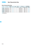
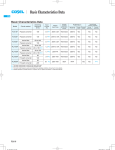
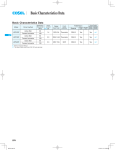
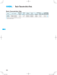
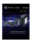
Basic Characteristics Data
Basic Characteristics Data
Model
Circuit method
Switching
frequency
[kHz]
SPLFA30F
Flyback converter
130
Active filter
60 - 440
Flyback converter
130
Active filter
60 - 440
Flyback converter
130
Active filter
60
Forward converter
140
SPLFA50F
SPLFA
SPLFA75F
SPLFA100F
SPLFA150F
*1
*2
*3
*4
Active filter
60
Forward converter
140
The value of input current is at ACIN 100V and rated load.
Refer to Instruction Manual 2.
Output side PCB.
Built-in power supply PCB.
SPLFA-12
Inrush
current
protection
Material
Single
sided
0.65
Thermistor
CEM-3
0.67
Thermistor
1.0
Input
current
*1 [A]
Series/Parallel
operation availability
PCB/Pattern
Double
sided
*2
Series
operation
Parallel
operation
Yes
Yes
No
CEM-3
Yes
Yes
No
Thermistor
CEM-3
Yes
Yes
No
1.3
Thermistor
CEM-3
Yes
*3
Yes
*4
Yes
No
2.0
Thermistor
CEM-3
Yes
*3
Yes
*4
Yes
No
AC-DC Power Supplies Open Frame/Enclosed Value-added Type
1
Instruction Manual
Function
SPLFA-14
1.1
Input voltage range
SPLFA-14
1.2
Inrush current limiting
SPLFA-14
1.3
Overcurrent protection
SPLFA-14
1.4
Overvoltage protection
SPLFA-14
1.5
Isolation
SPLFA-14
SPLFA
2
3
4
Series Operation and Parallel Operation
SPLFA-15
2.1
Series Operation
SPLFA-15
2.2
Parallel Operation
SPLFA-15
Assembling and Installation Method
SPLFA-15
3.1
Derating
SPLFA-15
3.2
Installation method
SPLFA-16
Option and Others
SPLFA-16
4.1
Outline of options
SPLFA-16
4.2
Others
SPLFA-16
SPLFA-13
AC-DC Power Supplies Open Frame/Enclosed Value-added Type
Instruction Manual
1.3 Overcurrent protection
1 Function
¡An overcurrent protection circuit is built-in and activated at 105%
of the rated current or 101% of the peak current. A unit automati-
1.1 Input voltage range
cally recovers when a fault condition is removed.
Please do not use a unit in short circuit and/or under an overcur-
¡Input voltage range of the power supplies is from AC85V to
AC264V (please see SPECIFICATIONS for details).
¡In cases that conform with safety standard DEN-AN, input voltage
range is AC100-AC120V (50/60Hz).
SPLFA
¡If input value doesn’t fall within above range, a unit may not operate in accordance with specifications and/or start hunting or fail.
rent condition.
¡Intermittent Operation Mode
Intermittent operation for overcurrent protection is included in a
part of series. When the overcurrent protection circuit is activated
and the output voltage drops to a certain extent, the output becomes intermittent so that the average current will also decrease.
If you need to apply a square waveform input voltage, which is
commonly used in UPS and inverters, please contact us.
¡When the input voltage changes suddenly, the output voltage accuracy might exceed the specification. Please contact us.
¿ SPLFA30F
1.4 Overvoltage protection
¡An overvoltage protection circuit is built-in. If the overvoltage protection circuit is activated, shut down the input voltage, wait more
than 3 minutes and turn on the AC input again to recover the out-
¡A power factor improvement circuit (active filter) is not built-in. If
you use multiple units for a single system, standards for input har-
put voltage. Recovery time varies depending on such factors as
input voltage value at the time of the operation.
monic current may not be satisfied. Please contact us for details.
¿ SPLFA30F, SPLFA50F, SPLFA75F,
SPLFA100F, SPLFA150F
¡Operation stop voltage is set at a lower value than that of a standard version (derating is needed).
-Use Conditions
SPLFA30F
SPLFA50F
SPLFA75F
SPLFA100F
SPLFA150F
10W
15W
25W
30W
50W
Input AC50V
Duty 1s/30s
*Please avoid using continuously for more than 1 second
under above conditions. Doing so may cause a failure.
1.2 Inrush current limiting
¡An inrush current limiting circuit is built-in.
¡If you need to use a switch on the input side, please select one
that can withstand an input inrush current.
¿ SPLFA30F, SPLFA50F, SPLFA75F,
SPLFA100F, SPLFA150F
¡Thermistor is used in the inrush current limiting circuit. When you
turn the power ON/OFF repeatedly within a short period of time,
please have enough intervals so that a power supply cools down
before being turned on.
SPLFA-14
1.5 Isolation
¡For a receiving inspection, such as Hi-Pot test, gradually increase
(decrease) the voltage for the start (shut down). Avoid using HiPot tester with the timer because it may generate voltage a few
times higher than the applied voltage, at ON/OFF of a timer.
Instruction Manual
AC-DC Power Supplies Open Frame/Enclosed Value-added Type
2 Series Operation and
Parallel Operation
2.2 Parallel Operation
¡Parallel operation is not possible.
¡Redundancy operation is available by wiring as shown below.
I1
Power +
Supply -
2.1 Series Operation
I3
Load
¿ SPLFA30F, SPLFA50F, SPLFA75F
¡Series operation is available by connecting the outputs of two or
more power supplies with the same output voltage, as shown below. Output current in series connection should be lower than the
lowest rated current in each unit.
D4
D1-D4 : Use a schottky barrier
diode with low forward
voltage.
Power +
Supply -
D1
Power +
Supply -
D2
Load
Power +
Supply - D3
15V or more
Load
D2
SPLFA
Fig.2.4 Example of redundancy operation
12V or less
Power +
Supply - D1
I2
Power +
Supply -
¡Even a slight difference in output voltage can affect the balance
between the values of I1 and I2.
Please make sure that the value of I3 does not exceed the rated
current of a power supply.
I3 [ the rated current value
D1,D2 : Use a schottky barrier
diode with low forward
voltage.
3 Assembling and
Installation Method
Fig.2.1 Examples of connecting in series operation (a)
Load
Power +
Supply -
3.1 Derating
Load
Power +
Supply -
¡The operative ambient temperature is different mounting position.
Derating curve is shown below.
Fig.2.2 Examples of connecting in series operation (b)
Note: In the hatched area, the specification of Ripple, Ripple
Noise is different from other area.
¿ SPLFA100F, SPLFA150F
¡You can use a power supply in series operation. The output current in series operation should be lower than the rated current of a
¿ SPLFA30F
1 (D), (E)mounting 1 (A), (C)mounting
1 (F)mounting
1 (B)mounting
2 (A) ~ (F)
mounting
power supply with the lowest rated surrent among power supplies
ceeding the rated current flows into a power supply.
Power +
Supply (a)
1Convection
2Forced air (0.5m3 / min)
60
40
20
0
-10
10
0
30
20
40
50
60
Ambient temperature [C]
Fig.3.1 Ambient temperature derating curve
(b)
Fig.2.3 Examples of connecting in series operation
¿ SPLFA50F
1 (C), (E)mounting 1 (B)mounting 1 (D)mounting
1 (F)mounting
1 (A)mounting
2 (A) ~ (F)
mounting
100
Load factor [%]
Power +
Supply -
80
Load
Load
Load
Power +
Supply -
Power +
Supply -
100
Load factor [%]
that are serially connected. Please make sure that no surrent ex-
80
1Convection
2Forced air (0.5m3 / min)
60
40
20
0
-10
0
10
20
30
40
50
Ambient temperature [C]
Fig.3.2 Ambient temperature derating curve
SPLFA-15
Instruction Manual
AC-DC Power Supplies Open Frame/Enclosed Value-added Type
¿ SPLFA75F
¡Mounting method
1 (D)mounting
1 (E), (F)mounting
100
Load factor [%]
(A)
1 (C)mounting
1 (A), (B)mounting
2 (A) ~ (F)
mounting
80
1Convection
2Forced air (0.5m3 / min)
60
40
0
10
20
30
40
50
(C)
Input wire
Standard position
20
0
-10
(B)
Input wire
Input wire
(D)
Input wire
(E)
(F)
Ambient temperature [C]
SPLFA
Fig.3.3 Ambient temperature derating curve
Input wire
¿ SPLFA100F
1 (E), (F)mounting
1 (A)mounting
1 (D)mounting
1 (B)mounting
1 (C)mounting
2 (A) ~ (F)
mounting
100
Load factor [%]
Input wire
80
75
1Convection
2Forced air (0.5m3 / min)
60
50
40
30
20
0
-10
10
0
20
25
30
Fig.3.7 Mounting method
3.2 Installation method
¡Installation Method
40
50
60
Ambient temperature [C]
Fig.3.4 Ambient temperature derating curve
Fig.3.8 Installation Method
¿ SPLFA150F
100
Load factor [%]
*Please fix the power supply with screws at installation.
1 (E), (F)mounting
1 (A)mounting
1 (D)mounting
1 (B)mounting 1 (C)mounting
2 (A) ~ (F)
mounting
80
70
60
50
40
1Convection
2Forced air (0.5m3 / min)
20
0
-10
0
5
10
20
25
30
40
45
50
55
Fig.3.9 Installation Method
60
Ambient temperature [C]
Fig.3.5 Ambient temperature derating curve
¡Derating curve depending on input voltage
Derating curve depending on input voltage is shown in Fig.3.4.
Please contact us for details.
4 Option and Others
[%]
Load factor
*Please fix the power supply with screws at installation.
*Derating curve changes in the case of attachment of Fig.3.9.
100
4.1 Outline of options
¿ -C
80
[AC V]
85 90
Fig.3.6 Derating curve depending on input voltage
-Option -C units have coated internal PCB for better moisture
resistance.
4.2 Others
¡While turning on the electricity, and for a while after turning off,
please don’t touch the power supply because that may be hot.
¡When a mass capacitor is connected with the output terminal (load
side), the output might become the stop or an unstable operation.
Please contact us for details when you connect the capacitor.
SPLFA-16