1
OPERATION MANUAL
Model 1010
TE Survey Meter
August 1998
Health Physics Instruments
330 South Kellogg Ave, Suite D
Goleta, CA 93117
GENERAL INFORMATION
This instrument is manufactured in the United States of America by:
Health Physics Instruments
Suite D
330 South Kellogg Ave
Goleta, CA 93117-3814
Tel: 805.964.3615
Fax: 805.964.3162
Email: [email protected]
Health Physics Instruments is a division of Far West Technology, Inc.
Both Health Physics Instruments and Far West Technology have been manufacturing radiation measuring
devices since 1972.
REPAIR SERVICE
Although we design and manufacture our instruments to a high standard, we realize that repairs are sometimes
necessary. If you believe service is needed on this instrument please call our service department before
shipping the instrument to us for repair; often we can help you with simple problems. If you do decide to return
it to us for repair then please include:
1.
2.
3.
4.
5.
6.
Contact person’s name
Organization or Company name
Address
Phone number of contact person
Description of the problem
Anything else you may think important
We will inform you of the repair charges and wait for your authorization before we repair your instrument.
TABLE OF CONTENTS
I.
GENERAL DESCRIPTION.................................................................................................................. 2
II.
USE .................................................................................................................................................... 2
III.
GENERAL CIRCUIT ......................................................................................................................... 2
IV.
ASSEMBLY....................................................................................................................................... 3
V.
CALIBRATION.................................................................................................................................. 4
A.
B.
ROUTINE RECALIBRATION............................................................................................................... 4
ORIGINAL CALIBRATION .................................................................................................................. 4
MAINTENANCE............................................................................................................................................ 5
VI.
REPAIR.............................................................................................................................................. 5
MODEL 1010 TE SURVEY METER
1
I.
GENERAL DESCRIPTION
The Model 1010 Survey Meter consists of a multiplying ion chamber, an electrometer with a metering circuit,
and the necessary power supplies. It has the following ratemeter ranges: 0-0.1 mrad/h, 0-1 mrad/h, 0-10
mrad/h, 0-100 mrad/h and 0-1000 mrad/h. It also has 0-0.01 mrad, 0-0.1 mrad, and 0-1 mrad integrating dose
ranges. The survey meter will measure the absorbed dose from any penetrating radiation including x-rays,
gamma rays, neutrons, and high energy Particles.
The multiplying ion chamber is a cylindrical tissue equivalent plastic shell, 2 " in diameter with a central loop.
The chamber is operated at about 1500 volts and the pressure of tissue equivalent filling gas is 10 cmHg. The
electrometer circuit measures the total charge collected by the central loop. Because of the sharp dependence
of gas multiplication on chamber voltage, the high voltage is regulated to about 0.1% by an integrated voltage
regulator and a feed-back loop.
II.
USE
The instrument is designed to measure low level penetrating radiation. Measurements of absorbed dose in noncontrolled areas in the vicinity of radiation sources may be performed quickly. The instrument normally reads
background levels of radiation on the 0. 01 mrad range.
When switching to the 0.1 mrad/h rate meter range, the meter may be driven off scale. By momentarily
switching to the reset position R and back to the 0.1 mrad/h range, the time constant capacitor will be
discharged and the meter will come back on-scale. Rapid switching of the range switch does not harm the
meter.
The instrument is independent of battery voltage until the voltage is insufficient to operate the power supply
oscillators. The battery check switch position, BAT, consists of a 6 volt voltmeter operated with the load on the
batteries. The instrument will operate properly at 4.5 volts.
For very low radiation level measurements, the integrating ranges may be used. The instrument should be
checked for leakage periodically by measuring background radiation drift rates on the 0.01 mrad scale.
Normally, time for full scale deflection (10 microrad) is about 1 hour, but it is dependent on location. If the drift
rate from background is known, differences in drift rates can be attributable to radiation sources.
The three absorbed dose ranges employ the same charging capacitor. Switching from one range to the next
does not destroy the measurement, The capacitor is discharged and the meter returned to zero by switching to
the reset position, R.
III.
GENERAL CIRCUIT
The Model 1010 Survey Meter consists of a detector, a low voltage DC to DC converter, a regulated high
voltage power supply, an electrometer and metering circuit, and a selector switch assembly. The two power
supplies are mounted on the printed circuit board. Three high impedance elements are used: 50 megohm
resistor for the x 100 and x 1000 rate meter ranges, 50,000 megohm resistor for the x 0.1, x 1 and x 10 rate
meter ranges, and a 6000 pF capacitor for the integrate ranges. The metering circuit, the components of which
are mounted on the switch sections, presents a constant impedance to the electrometer output and uses 1%
resistors to obtain accurate decade steps. Only three calibration adjustments are available, one for each high
impedance element.
The electrometer is a plug-in unit of the varactor bridge type. Zero adjustment is available to cancel the offset
voltage. The DC to DC converter supplies +/-12 v to the electrometer and +12v to the high voltage power
supply from the 6 v batteries. The high voltage power supply is regulated with an integrated circuit precision
voltage regulator with a feed-back loop using an FET. A high voltage adjustment is available. All adjustments
are located in the battery compartment.
MODEL 1010 TE SURVEY METER
2
IV.
ASSEMBLY
1. The following order is recommended to disassemble the instrument:
2. Remove the end plate by removing the 4 rubber feet to replace batteries or make calibration
adjustments.
3. Remove bottom plate by removing 4 rubber feet and 2 screws. Range switch, electrometer, circuit
board and meter are available.
4. Remove 2 screws on edges of circuit board. Circuit board may now swing up so that components
are available.
5. Remove knob and selector switch nut and withdraw the signal lead from connector in detector.
Selector switch can swing out of the chassis without disconnecting leads.
6. Remove electrometer by removing 2 4-40 screws available under circuit board. Pry the
electrometer from the socket and swing socket out of way.
7. Remove the meter by disconnecting the 3 wires. Remove the two 4-40 nuts holding the front panel
to the instrument case. These nuts have spacers under them and are located in the comers of the
meter compartment beside the meter. This will permit the meter and front panel to be removed as
a unit.
8. Remove detector by withdrawing the 2 jacks and removing the 4 mounting nuts.
MODEL 1010 TE SURVEY METER
3
V.
CALIBRATION
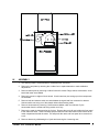
The overall sensitivity is adjusted by setting the high voltage. See Figure 3. The three calibration adjustments
are to allow for the 10% tolerances on the high impedance elements. One of these, CAL INT, sets all integrate
ranges CAL LO sets the x 0.1, x 1, and x 10 rate meter ranges, and the third, CAL HI, sets the x 100 and x
1000 rate meter ranges. The decade steps are fixed by the metering circuit.
To properly calibrate the instrument in mrads with known exposure rates from Co-60 or Cs-137, a factor of 0.96
must be used to obtain tissue rads from exposure in R (NCRP quotes 0.957). If the exposure rate at some
location is known to be 10 mR/h, the instrument should read 9.6 mrad/h.
Two calibration procedures will be described; a routine calibration and an original calibration. Normally, only
the former will be required.
A.
Routine Recalibration
1. All adjustments are in the battery compartment. The
procedure is to check the accuracy of the x 10 mrad/h,
x 100 mrad/h, and the 1 mrad ranges. If one is off or in
10 mR/h field and note meter reading. It should be 9.6
mrad/h.
2. Observe accuracy of 100 mrad/h range.
3. Observe accuracy of 0.1 mrad dose range. Time for
full scale deflection in a 10 mR/h field should be about
37 sec.
4. If all ranges are off uniformly, adjust high voltage, If one range is off, adjust the proper calibration
control.
5. Check operation on all ranges. The meter should be able to go off scale on the 10 mrad/h and the
1 mrad ranges.
B.
Original
Calibration
1. Check zero by setting range switch on R.
2. Check battery condition and replace batteries if
necessary.
3. Place CAL LO control in about the center. Place
center of chamber in a 10 mR/h field from Co-60 or
Cs-137 and adjust high voltage, HV, to give a meter
reading of 9.6 mrad/h.
4. Place center of chamber in a 100 mR/h field and
adjust CAL HI to give a reading of 96 mrad/h.
5. Place center of chamber in a 10 mR/h field and the
range switch on R. Turn range switch to x 0.1 mrad
position and time full scale deflection. Adjust CAL
INT, so that full scale deflection takes 7 sec. If it is
not possible to calibrate all three ranges because of limitations of the controls, readjust high voltage
slightly and repeat steps 3, 4 and 5.
Place the chamber near a source and check for off-scale deflection on the x 10 mrad/h and I mrad ranges. It is
possible to have the instrument in calibration and the meter not be able to read full scale deflection on these
ranges. If this is the case, decrease HV slightly and repeat the calibration.
MODEL 1010 TE SURVEY METER
4
MAINTENANCE
CAUTION: HIGH VOLTAGE EXISTS AT THE CHAMBER AND ON THE CIRCUIT BOARD.
The only routine service required is the replacement of batteries and the calibration. Any type of 1. 3 to 1. 5
volt batteries of the D size may be used, such as carbon dry cells or alkaline cells.
VI.
REPAIR
CAUTION:
After removing the bottom panel, the high megohm resistors are exposed. They are mounted
on the switch section nearest the back panel. Because of their small size, they may be overlooked. Do not
handle these resistors with your fingers, as they will change resistance and alter the calibration.
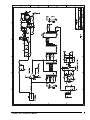
The location of all parts is shown in the drawings or in the parts list. Normal operating voltages of the critical
locations are shown in the circuit diagram.
If difficulties are experienced, determine whether the circuit or the chamber is faulty. If the voltages check out,
the high voltage power supply is not at fault. Disconnect the chamber by withdrawing the jack from the center of
the chamber and note the reading when the instrument is turned on. The meter should approach zero and
possibly dip slowly below on the x 0.1 rate meter range.
If the chamber is at fault, it can be tested if an electrometer such as a General Radio or Keithley is available.
With the high voltage from the instrument applied, (~1300V) the current should be about 2 x 10-11 amps/mR/h
from gamma rays. The current should approach zero and individual events should be observable at
background radiation levels. The chamber is sealed and no repairs can be made in the field.
If resistors in the regulator circuit are replaced, 1% metal oxide types are required. If carbon resistors are used,
the instrument will be temperature dependent. If resistors in the switch sections are replaced, 1% metal oxide
types are required for accurate calibrations on all ranges.
MODEL 1010 TE SURVEY METER
5
MODEL 1010 TE SURVEY METER
6