1
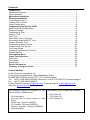
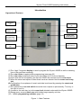
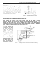
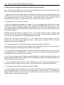
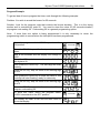
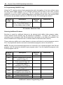
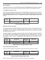
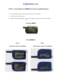
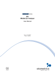
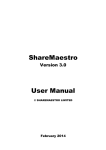
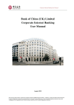
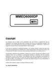
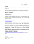
Handbook for the Wyvern® 2000R Timer Part Number 918-000-746 July 2008 Issue Number 5 (Version 8.26) Contents Introduction.............................................................................................................. 1 Operational Features ................................................................................................. 1 Timer Operation......................................................................................................... 2 Mechanical Installation ........................................................................................... 3 Electrical Installation............................................................................................... 4 Good Wiring Practice ................................................................................................ 5 Voltage Free Contacts ............................................................................................... 6 Wiring Connections … ............................................................................................... 8 Programming the Wyvern 2000R...........................................................................10 Selecting Programming Mode...................................................................................11 Program Example .....................................................................................................13 Programming Time ...................................................................................................14 Session Time ............................................................................................................15 Coin Time .................................................................................................................16 Start Delay Time or Pre-time ....................................................................................17 Secondary Output ON/OFF Time .............................................................................18 Lockout & Buzzer Time.............................................................................................19 Programming Money Values.....................................................................................20 Programming Coin Values ........................................................................................21 Coin Learn Mode ......................................................................................................22 Auxiliary Programming Functions .............................................................................24 Special Options.........................................................................................................27 Interrogation Menu .................................................................................................28 Smart Card Operation ............................................................................................30 User Card .................................................................................................................31 Profit Share...............................................................................................................33 Specification .............................................................................................................35 Service Information ................................................................................................36 Summary of Program Codes .................................................................................37 Contact Address: Leisure Controls International Ltd Clump Farm Industrial Estate, Higher Shaftesbury Road, BLANDFORD FORUM, Dorset. DT11 7DT. United Kingdom Tel: +44 (0) 1258 489075/455393 (General) or +44 (0) 1258 483574 (Technical support) Fax: +44 (0) 1258 488526/456410 E-mail: General enquires: [email protected], Technical support: [email protected] Web Site: www.lci.gb.com The following options are available for use The following input voltages are available: with the Wyvern 2000R timers: 230V 50Hz 7A 7kVA switching 115V 60Hz 7A Key over-ride or panic button or start 24V 50/60Hz 7A button Smart card (Wyvern 2000RS) PC interface (Wyvern 2000RPC) Network interface (Wyvern 2000RCN) Remote display ©2000 - 2008. Wyvern is a registered trade mark of Leisure Controls International Ltd Wyvern Timer 2000R Operating Instructions 1 Introduction Operational Features Coin Entry (3) Coin Sticker (2) Over-ride Switch (7) Display (1) Smart Card Pushbutton (6) Hidden Programming Switches (10) Smart Card Entry Slot (5) Coin Return (4) Steel Case (9) Cover Lock (8) (1) The 4 digit 7 segment display is used to program the Wyvern 2000R as well as showing time of day and time remaining. (2) The coin sticker is applied after programming (see page 23) (3) The coin entry accepts all sizes of coin and token up to 31mm in diameter (4) Coins that are not accepted by the Wyvern 2000R are returned into the coin return (5) When the smart card option is fitted smart cards are inserted into the smart card entry slot (6) Confirmation of acceptance of smart card data is achieved by pressing the smart card pushbutton (7) The optional key over-ride switch turns the timer outputs on permanently. Turn key to the right to turn on (8) Access to the cash tray is via the cover lock situated underneath the Wyvern 2000R (9) Strong epoxy covered steel case with hidden large capacity coin box (10) Hidden programming switches (page 13) Figure 1 – Main Features 2 Wyvern Timer 2000R Operating Instructions The Wyvern 2000R Timer offers an extensive range of features to suit virtually all coin/card timer applications. Advanced electronic control provides programmable options allowing up to six different coins to be recognised, peak and off-peak timing cycles, smart card operation, together with profit sharing facilities. Both switched outputs are voltage free; this means the Wyvern 2000R can be used to switch a load operating from any voltage, not just mains operated equipment. A full description of voltage free and load switching appears on pages 6 and 7. Figure 1 shows the main operational features and this manual provides all information for correct installation and programming. Timer Operation The Wyvern 2000R may be programmed to operate in one of four modes as described below. The explanations all use UK coinage as examples but the principles apply for all currencies. 1. Fixed time For fixed time operation the session cost or session time options are not programmed, so the Wyvern 2000R operates using the times allocated to the coins (options 31 to 42, page 16). The timer turns ON as soon as the first coin is inserted and the time incremented with each additional coin. 2. Session time With session time sufficient coins must be inserted to meet a specified amount of time before the timer turns ON. To activate session time options 08 to 09 are programmed (page 15), but not session cost (options 04 to 05, page 20). The timer will only activate when coins equalling the session time have been inserted. For example if the Wyvern 2000R were programmed with a session time of 19 minutes the timer would only start when coins equal to 19 minutes are inserted. The timer will flash the character ‘A’, and display the total time as each coin is added. Upon insertion of the final coin, the display will show 19:00 and the timer will turn ON and start counting down 3. Session cost With session cost sufficient coins must be inserted to meet a specified price before the timer turns ON. To activate session cost options 04 to 05 are programmed (page 20), but not session time (options 08 to 09, page 15). The timer will only activate when coins equalling the session cost have been inserted. For example if the Wyvern 2000R were programmed with a session cost of £3.80, the timer would only start when coins to the value of £3.80 are inserted. The timer will flash the character ‘A’, and display the total amount of money added. When the displayed value reaches 380, meeting the £3.80 session cost, the timer will turn ON, and start counting down. 4. Combined session cost and session time With combined session cost and session time sufficient coins must be inserted to meet a specified price before the timer turns ON for a specified time, even if this time is different from the time allocated to the coins making up the session cost. To activate combined session cost and time, options 04 to 05 (page 20) and options 08 to 09 (page 15), are programmed. The addition of further coins is influenced by program code 30 (page 26). Once the initial cost is met, if program code 30 is not set, further coins will add the time allocated for that coin (codes 31 to 42, page 16). If program code 30 is set to proportional session (3004) further coins to meet the session cost must be inserted. For example If the Wyvern 2000R were programmed with a session time of 5 minutes and a session cost of £3.80, the timer would turn ON after £3.80 has been inserted and would run for 5 minutes. With program code 30 set to proportional session coins totalling £3.80 must be inserted for an additional 5 minutes. However if program code 30 Wyvern Timer 2000R Operating Instructions 3 is not set further coins inserted ignore the combination and the timer is incremented by the time allocated to that coin. Note: Lockout time must not be set to a value less than the session time for modes 2, 3 or 4 Using the previous examples the table below shows the status of the display and state of the timer outputs as coins are inserted from coin 1 through to coin 6. The table assumes that coin 2 is inserted after coin 1 and so on. Coin No. 1 2 3 4 5 6 Value Time 10p 20p 50p £1-00 £2-00 £3.80 ɫ 30 sec 1 min 2 ½min 5 min 10 min 19 min Fixed Time 00:30 01:30 04:00 09:00 19:00 38:00 ON ON ON ON ON ON Session Time = 19 min A0:30 OFF * A1:30 OFF * A4:00 OFF * A9:00 OFF * 19:00 ON 38:00 ON Session Cost = £3.80 A010 OFF * A030 OFF * A080 OFF * A180 OFF * 19:00 ON 38:00 ON Combination £3.80 = 5 min A010 OFF * A030 OFF * A080 OFF * A180 OFF * 05:00 ON 10:00 ON ˭ Notes ɫ Coin 6 would be a token programmed for a value of £3.80 and a time of 19 minutes * A will flash on the display and indicates that further coins need to be inserted to turn the timer ON ˭ Program code 30 set to proportional session Values and times are for peak sessions only. Mechanical Installation The Wyvern 2000R Timer should be mounted on a smooth vertical wall away from corners, so its front door can be opened fully to allow easy access to the coin box and internal components. The timer is 275mm high by 204mm wide and has a depth of 90mm, so allow at least 210mm clearance from any corner wall. Take care to mount the case level in both the vertical and horizontal axes, failure to do so may prevent the coin mechanism from operating correctly. Choose an area where an ambient temperature of 40°C is not exceeded, away from any source of moisture, dust or direct heat. Note. If during the installation it is necessary to remove the ribbon cable connecting the two circuit boards, you must re-program the real time clock once the boards are re-connected. Power consumption of the timer is approximately 10W (at 230V AC). Loads of up to 1kVA (3A resistive) can be switched directly by the timer. This is typically five 100W incandescent or two 100W fluorescent lamps. Adding the 7kVA option increases the capacity up to a maximum of 7kVA (30A resistive), which is typically one 7kW shower or 12 fluorescent lamps. When used as a voltage free switch, the timer can be used with external switching contactors to control high current loads. See pages 6 and 7 in the Electrical Installation section for a description of voltage free switching. 4 Wyvern Timer 2000R Operating Instructions 1. Lay the timer on its back and open the case using the key supplied. Remove the cash box and using a small flat bladed screwdriver remove the 3mm screw (M3 x 6) holding the safety cover in place, as shown in Figure 2. Once the screw has been removed the cover may be lifted and unhooked from the main case to fully expose the back of the case and the main circuit board. Figure 2 – Removing Circuit Board Cover 2. The timer has three fixing holes arranged in a triangular formation, pre-drilled in its back cover. Position the case on the wall and mark the position of the uppermost single fixing hole (the one in-line with the cable knockouts). Remove the timer and plug the wall and fit with No. 8 or 10 screws of not less than 22mm. Hang the timer case on this screw and tighten, use a spirit level to check the case is level both vertically and horizontally. Mark the bottom two screw positions, remove case and plug the wall. 3. Remove the required cable knockouts, and fix to the wall. If the case is not level the coin mechanism may not work. Electrical Installation The timer will require a fused double pole switch for the mains input. Wire the unit as shown in Figure 7 using appropriately rated and approved cable conforming to the relevant regional standards. Minimum wire sizes for European usage are given on page 8. With the configuration of Figure 7 the total load current (the combination of main output and secondary output) is 3.15A, limited by the size of the main circuit board’s track width. If required to switch a total load current greater than 3.15A, the circuit board track limitations can be overcome by externally wiring the relays to switch 3.15A each, giving a total switching capacity of 6.3A. See Figure 8 for the circuit arrangement. Note: each relay is fuse protected and cannot switch more than 3.15A. If replacing a blown fuse ensure the replacement is a type T HBC with 250V breaking capacity. It is essential that the safety earth is connected to a known good earth at the same bonding point as the main earth for the load being switched by the Wyvern 2000R. Poor earthing or bad routing of connecting cables could create electrical noise leading to erratic operation of the Wyvern 2000R. See following page for good wiring practice. Wyvern Timer 2000R Operating Instructions 5 Good Wiring Practice to Reduce Susceptibility to Electrical Noise The Wyvern 2000R has been designed to reduce the amount of electrical noise seen by the control circuits, however bad grounding or inappropriate wiring techniques can create noise problems that overwhelm the control system. A symptom of electrical noise is randomness, both in the occurrence of the problem and in what the Wyvern 2000R does in its failure. The built in noise protection of the Wyvern 2000R is dependent on a good ground connection which usually short-circuits any electrical noise to earth. Without a good, correctly installed ground connection the noise protection is essentially defeated. Ground current Induced by noise Load that may generate noise Extra ground connection causes ground loop and acts as an aerial for noise Ground point Wyvern 2000R Noise voltage caused by ground current flowing through wire impedance. Wyvern 2000R experiences noise on its ground connection. At installation the best approach is to establish a central grounding point for the load and the Wyvern 2000R. The illustration opposite shows bad grounding technique. By connecting the grounds together and then routed through a single wire to the grounding point, any noise generated by the load is superimposed on the ground of the Wyvern 2000R. Ground current Induced by noise. Bad Grounding Technique Proper grounding technique dictates using separate ground wires from the timer and the load to a central grounding point as shown opposite Load that may generate noise The separate wire for the Wyvern 2000R protects it from sharing the noisy ground wire from the load. Wyvern 2000R Ground point Very little noise voltage is present because of low impedance to ground at the connection point Good Grounding Technique The separation of power cables is another practice that helps increase noise immunity in the installed system. If any of the input or output wires connecting the Wyvern 2000R to the load are bundled closely together with the power wiring of the load then noise currents can be transformer coupled to the Wyvern 2000R. Always keep wiring from the timer away from motors, solenoids, inductors and similar devices; if necessary use shielded cable with only one end of the shield connected to ground. Following good wiring practices as detailed above will enhance the noise protection already built into the Wyvern 2000R. 6 Wyvern Timer 2000R Operating Instructions Voltage Free Contacts The timer controls the operation of external equipment by a relay, which turns power ON and OFF. As supplied, the timer’s relay contacts are said to be ‘voltage free’, which means they have no connections made to them, as shown in Figure 3. Figure 3 - Voltage Free Relay Contacts To be able to use the relay contact to switch equipment ON and OFF, it needs to be wired as shown in Figure 4. This shows a light bulb being powered from the mains, but any source of power could be used, so long as it is wired via the timer’s main output relay contact. Figure 4 - Relay Contacts Wired to Control a Lamp Wyvern Timer 2000R Operating Instructions 7 On the timer's main circuit board connectors CN5 & CN6 already have a source of mains power connected to pin1. This is supplied via a circuit board track from the mains live input on CN3. Therefore, the mains ‘L’ (live) wire can be taken from pin 1 of CN5. The ‘N’ (neutral) wire can be connected to pins 1, 2 or 3 of CN3 where a direct connection to the mains neutral input can be made. These connections are shown in Figure 5. Figure 5 - CN3 and CN5 Final Wiring Use of Voltage Free Contacts in the Wyvern 2000R Timer Using voltage free contacts, the Wyvern 2000R Timer can be used to control equipment operating from a range of voltages, not just mains powered devices. For example, the timer could control +24V DC supplies just as easily as AC mains supplies. Supplying the timer with voltage free contacts does involve a slight overhead in installation wiring, but gains a greater versatility in the ways it may be used. The relay contacts are voltage free - they have not been pre-wired to supply a particular voltage when the contacts are closed. This means you can use the contacts to turn-ON a supply of your choice. For example, Figure 6 shows how a 24V DC supply can be controlled via the main output. This can switch up to 3.15A, which is adequate for most external contactors. Figure 6 – Voltage Free Contacts & External Buzzer Wiring 8 Wyvern Timer 2000R Operating Instructions Wiring Connections Cable and fuse size: With 24V, VF (volt-free) and 1kVA loads use cable of cross-sectional area not less than 1.0sq. mm (1mm2) and externally fuse at 5A. With 7kVA rated models use cable of not less than 6.0sq. mm (6mm2) and externally fuse as appropriate up to a maximum of 30A. The use of 20mm conduit is recommended (use male thread adaptor with lockring, for example Ega type EMA 1ZM). Alternatively fit a 20mm nylon compression cable gland to provide strain relief. Figure 7 – Mains Wiring The high current connections shown in Figure 8 are required only if the total current of both outputs exceeds 3.15A. Refer to page 3 of the electrical installation section for further details. Figure 8 - High Current Connections WARNING THE TIMER CASE MUST BE SECURELY CONNECTED TO A KNOWN EARTH Refer to page 5 Wyvern Timer 2000R Operating Instructions 9 Optional 7kVA Output Timers fitted with the optional 7kVA output have the main output relay mounted off-board. This is wired as shown in Figure 9 The 7kVA circuit can be used to switch currents of up to 30A (resistive load), and will require a suitable fuse to be fitted on the mains input side to protect whatever load is connected. Figure 9 – 7kVA Option Wiring External Buzzer Connections You can wire an external buzzer, or relay, to the timer using connector CN7. Use a 12V piezo-electric buzzer or a relay with 12V dc coil with the positive (+) side wired to the left-handside (pin 1) of connector CN7. The buzzer or relay is driven from an open collector transistor mounted on the main circuit board and is wired as shown in Figure 6. In both cases maximum current consumption must not exceed 100mA. External Input Connections Where the timer is to be controlled remotely, using externally connected push-button switches; the connections available on CN2 can be used. These inputs are optically isolated and require a low current +12V DC supply to operate correctly. Where the external buttons are only mounted a few metres away from the timer, they can be supplied directly from the timer itself. But if mounted tens of metres away, they will require an externally generated +12V DC supply to operate reliably. The two possible circuit arrangements are shown in Figure 10, which also illustrates the wiring of the HOLD switch, used when it is required to turn the timing function on and off remotely. When controlled from a remote location, pressing the start push-button will start the timer regardless of any pretime/start delay that may have been set. Pressing the stop push-button will immediately stop the timer. The secondary output may or may not turn off when the external stop push-button is pressed depending on the setting of special option program code 01 (see page 18). If a single ON/OFF HOLD switch is used in place of the start push-button and program code 28 ‘set remote hold’ is selected (see page 24), the timer can be turned ON or OFF from a remote location. With the switch ON the timer behaves normally, but stops timing when the switch is turned OFF, only to restart when the switch is turned ON again. All external inputs will only be recognised if program code 23 is set ON (see page 24). 10 Wyvern Timer 2000R Operating Instructions Figure 10 - External Inputs For Local and Remote Wiring Programming The Wyvern 2000R To control the operation of the timer, for example to let it know when to charge at peak rate, or how much time to allow for each coin inserted, it needs to be programmed. This consists of entering two digit numbers or options into various empty memory locations, identified by program code numbers (00 to 63). You step forwards or backwards through the program code number to where you wish to make a change, alter the settings, and then return the timer to normal operation. If you don’t wish to use all the timer’s facilities those code numbers can be ignored and left blank. For example, if you wished to set the timer to wait 2 minutes before switching ON whatever was being controlled (start delay time), you would select the general programming mode, choose program code 00 and alter the two digit contents to 02. This will program the pretime as 2 minutes. The display is as shown in Figure 11. For a complete programming example see page 13. Figure 11 – Programming Start Delay Time Wyvern Timer 2000R Operating Instructions 11 Selecting programming modes Before changing the two digit values held in each program code number setting, it is necessary to place the timer into programming mode. Place the programming template (shown in Figure 12), over the timer front panel logo (covering the name Wyvern 2000). The template shows the positions of three hidden programming buttons. Note: these buttons cannot be used until the programming switch is turned ON. Together with the front panel four digit display, these three buttons allow program code numbers to be selected to customise the timer. Three menus are possible: 1. Setup programming. DOWN button. Selected using the 2. Special options. Selected using the PROG button. See page 27 3. Interrogation mode, total coin count or hours used. Selected using the UP button. Note: If the wrong button is pressed, return the programming switch to its normal position, wait for ‘Stor’ to be displayed then return to the programming mode once more. Figure 12 – Programming Template The programming switch is mounted on a circuit board held inside the front opening part of the timer case. Open the timer case door to its full extent and look to the right hand side of the coin mechanism (attached to the back of the door), where a circuit board as shown in Figure 13 will be visible. The programming switch is marked LKSW1, this needs to be slid gently upwards to put the timer into its programming mode. LKSW1 must be left in the programming mode position until all programming has been completed, when it can be slid down into its normal operating position. Returning LKSW1 to its normal down position will automatically store all the programming information previously entered. Figure 13– Position of LKSW1 12 Wyvern Timer 2000R Operating Instructions To alter program settings follow the procedure described below: Note: The UP and DOWN keys do not zoom (automatically increment when held down) and once at ‘9’ the display remains at ‘9’ until altered. 1. Apply power to the timer and the Wyvern 2000R should power up, finally displaying the time (in 24-hour format) on its 4-digit display. Using the key supplied open the front cover and set the programming switch to the ON position. Keep the switch in this position until all programming is complete, and then return it to the normal OFF position (at step 9). 2. Close the front cover and lock in place. 3. With the programming template in position, a choice of programming mode can be made using the UP, DOWN or PROG buttons. Note: pressing the DOWN button will give you access to all the general programming options, while selection of the UP button gives access to the interrogation options. Pressing the PROG button gives access to special options menu and is described on page 27. Pressing DOWN will flash the message ‘Prog’ on the display and will select program code 00, which is the first general programming memory location. General program locations 00 to 63 on the coin reject timer can be programmed in this mode. Pressing UP will flash the message ‘Tot’ on the display and will select program code 00, which is the first total money memory location. Interrogation locations 00 to 05 can be selected in this mode (see page 28). 4. To start programming, choose the program mode by pressing the DOWN key. At this point the first two digits of the display are indicating the program code (00) and the second two digits are indicating the value stored at this location. 5. To change the contents of program locations, choose the program code you wish to alter by pressing the UP or DOWN keys. This will increment or decrement the first two digits of the display until you reach the required number. 6. At the chosen program code setting, press the PROG key, and the third digit (first digit of the stored value) will start to flash. Using the UP and DOWN keys select the required number and press the PROG button to accept it. 7. The last display digit will start to flash, indicating it is now ready for programming to the required number in a similar way to the first. Press PROG button to complete the selection. 8. To program further options repeat from step 5 onwards. 9. Once programming is complete, open the timer case (with power still applied) and return the programming switch to its normal ‘run’ mode (slide the switch DOWN). The display will briefly indicate the word ‘Stor’ (for store the settings) and will once more return to its clock display mode, ready for timing operations. Wyvern Timer 2000R Operating Instructions 13 Program Example To get an idea of how to program the timer, work through the following example: Problem: You wish to sound the buzzer for 25 seconds. Solution: Look for the program code that controls the buzzer duration. This is in the timing section and is controlled by code 20. You need to store the value 25 (25 seconds duration) at program code setting 20. Code setting 20 is a general programming option. Note: If more than one option is being programmed it is only necessary to return the programming switch to normal when the last option has been programmed. Move the program switch LKSW1 upwards to the ON position Press the DOWN key and the front panel display will show Wait a few seconds and the display will change to 0000 Press the UP key to increase the value of the first two digits to 20 Then press the PROG key. The third digit will start flashing Using the UP key, step the value of the flashing digit up to 2 Then press the PROG key to enter the value 2, the final digit will start flashing, ready for data entry Using the UP key, step the value of the flashing digit up to 5 Press the PROG key to enter the data value 25 into program code setting 20 To store this value, return the program switch LKSW1 downwards to the OFF position The display will flash STOR and will then return to its normal display 14 Wyvern Timer 2000R Operating Instructions Programming Time This section describes how all timing options are programmed within the Wyvern Timer 2000R. Selecting Hours or Minutes (program code 22) Certain timing operations have the option of being timed in hours and minutes or minutes and seconds. Program code 22 allows the selection of hours and minutes or minutes and seconds. This option applies to all timing functions except the start delay/pre-time and fan time options which are only available in minutes and seconds. Use the UP and DOWN buttons to change between ON and OFF options. In the following sections the Value Used column can be used to note your own settings. Program Code 22 Description Select hours or minutes Hours & minutes=ON or Minutes & seconds=OFF Maximum Value - Value Used Hours or Minutes Programming Codes Setting the Time of Day A real time 24-hour clock is fitted to the coin reject version of the timer. Time is set using program code 62. Once program code 62 is selected, pressing the PROG button will start to flash the very first digit of the 4-digit display. In the normal manner, the UP and DOWN buttons can be used to set the first 2 digits to the required hours and the last 2 digits to the required minutes. The clock is set following the last press of the PROG button for minute entry. If you do not require the 24-hour clock display, set the time to 00:00. This will not change the count-down operation of the display, but once zero time has been reached the display will permanently display 00:00, with a flashing colon (:). Program Code 62 Description Setting the real time clock Maximum Value - Setting the Real Time Clock Value Used Wyvern Timer 2000R Operating Instructions 15 Setting Session Times and Peak/Off Peak Times The Wyvern 2000R Timer can be programmed with peak and off peak session times (codes 08 to 15). Peak Time allows a premium session rate to be charged when demand is high, giving you the opportunity of maximising profits during busy periods. Off Peak Time can be set to coincide with less busy periods where cheaper rates can be offered to attract more business. Session times can be programmed as a time period in hours and minutes or minutes and seconds, depending on the setting of Program Code 22. The time at which peak rate starts or off peak rate starts can also be programmed, each time requiring a further two program codes – one for hours and the other for minutes. Note: Program codes are generally programmed as a pair, the first giving a value in hours or minutes and the second, a value in minutes or seconds. Program codes summarising all of these timing options is presented in the table below: Program Codes 08 09 10 11 12 13 14 15 Description Peak session time in hours or minutes Peak session time in minutes or seconds Off peak session time in hours or minutes Off peak session time in minutes or seconds Peak time ON in hours Peak time ON in minutes Off peak time ON in hours Off peak time ON in minutes Maximum Value - Value Used MAX 59 MAX 59 MAX 23 MAX 59 MAX 23 MAX 59 Time Programming Codes Note: If you program the peak and off peak times to overlap, the peak time takes precedence. See also session cost (page 20), selecting additional features (page 26) and combination of cost and time (page 2). 16 Wyvern Timer 2000R Operating Instructions Coin Time This allows a period of time to be allocated to a particular coin value. For each coin type, time can be programmed as a period in hours and minutes or minutes and seconds, depending on the setting of Program Code 22. Remember, these options must match the coin order of the coin value and coin learn modes. Program Codes 31 32 33 34 35 36 37 38 39 40 41 42 Description Coin 1 time in minutes/hours Coin 1 time in seconds/minutes Coin 2 time in minutes/hours Coin 2 time in seconds/minutes Coin 3 time in minutes/hours Coin 3 time in seconds/minutes Coin 4 time in minutes/hours Coin 4 time in seconds/minutes Coin 5 time in minutes/hours Coin 5 time in seconds/minutes Coin 6 time in minutes/hours Coin 6 time in seconds/minutes Maximum Value - Coin Time Programming Codes Value Used Wyvern Timer 2000R Operating Instructions 17 Start Delay Time or Pre-time This is the time between inserting money or a card into the timer and the timer turning ON. As soon as you start inserting coins or card and press the blue button, the display shows the time purchased for a period determined by option 21. Once option 21 times-out the display will show the programmed pre-time, along with a flashing ‘P’.* Inserting further coins or pressing the smart card blue button will again cause the display to show the total time purchased for a time determined by option 21. *Note: If option 21 is set to zero pre-time is not displayed. A further option (program code 27) allows the secondary output to be switched ON or OFF during this pre-time period. Program Codes 00 01 21 27 Description Start delay time in minutes Start delay time in seconds Time purchased display time Secondary output on = ON Secondary output off = OFF Maximum Value 59 59 59 - Start Delay Time Programming Codes Value Used 18 Wyvern Timer 2000R Operating Instructions Secondary Output ON/OFF Time Equipment controlled by the Wyvern Timer 2000R may require a secondary output to continue running following the end of the timed operation (for example a fan operated cool-down period). The secondary output program codes only allow you to set this time in minutes and seconds. During the run-on period the display may flash ‘Cool’, depending on how program code 25 has been set. Additionally by selecting program code 3002 coin lockout may be activated during cool down. Further options include the use of program code 27 to allow the secondary output to be switched ON or OFF during the start delay or pre-time, and program code 28, which allows the keyswitch to control the secondary output operation. Program Codes 02 03 25 27 28 Description Secondary output time in minutes Secondary output time in seconds Display of ‘cool’ = ON Display blank = OFF Secondary output on = ON Secondary output off = OFF When keyswitch is active, secondary output is on=ON When keyswitch is active, secondary output is off=OFF Maximum Value - Value Used - Secondary Output Time Programming Codes Additionally to the options described above special option program code 01 (see page 27) determines whether the secondary output remains on or turns off when the external stop, or optionally fitted emergency stop switch, is pressed. With special option program code 01 set to OFF (default factory setting) both the main and secondary outputs turn off and all remaining time is cancelled. If special option program code 01 is set to ON only the main output turns off and the secondary output remains running for the time determined by program codes 02 and 03. The external input must be enabled with program code 26 (see page 24). Special Code 01 Description Secondary output = ON Secondary output = OFF Maximum Value - Emergency Stop Special Option Code Value Used Wyvern Timer 2000R Operating Instructions 19 Lockout Time A safety feature built into the Wyvern 2000R Timer is the ability to prevent the timer from exceeding a maximum time despite a customer inserting more coins or a card. This lockout time is particularly useful in setting a limit to the exposure of UV radiation in tanning bed applications. Lockout will activate once a defined maximum time has been exceeded. During this time, the display will flash an ‘L’ character to indicate lockout is active and additional coins are rejected. If program codes 16 and 17 are set to zero lockout is not operative. Important: Do not set lockout time to a value less than the session time (options 08 and 09). Lockout can be initiated after the insertion of the first valid coin by using program code 3008, during cool down with program code 3002 (page 26), or at the end of pre-time with special option code 00. Program Codes 16 17 Special Code 00 Description Lockout time in hours or minutes (see program code 22) Lockout time in minutes or seconds (see program code 22) Description Normal operation = OFF Lockout at pre-time end = ON Maximum Value - Value Used 59 Maximum Value - Value Used Lockout Time Programming Codes Buzzer Time To warn that a timed operation is coming close to ending, a buzzer may be sounded. Buzzer ON time is the time the buzzer is sounded before the timer switches OFF. Buzzer duration is the time for which the buzzer is sounded. To select the buzzer duration time in minutes select program code 3001 (see page 26) Program Codes 18 19 20 Description Buzzer ON time in hours or minutes (see program code 22) Buzzer ON time in minutes or seconds (see program code 22) Buzzer duration time in seconds Maximum Value MAX 59 MAX 59 MAX 59 Buzzer Time Programming Codes Value Used 20 Wyvern Timer 2000R Operating Instructions Programming Money Values This section tells you how to program the cost of sessions, and the value given to each coin type. The options described are selected using the general programming mode. The amount of money collected can also be examined, using the interrogation mode, described at the end of this section. Note: In a similar manner to time, program codes are generally programmed as a pair, the first giving a value in a particular country’s base currency (such as pounds or dollars) and the second, a value in one hundredths of the base currency (such as pence or cents). Session Costs Peak and off-peak session costs can be programmed using program codes 04 to 07. This allows you to charge at two rates within any 24-hour period. Program Codes 04 05 06 07 Description Peak session cost in base currency Peak session cost in hundredths of base currency Off peak session cost in base currency Off peak session cost in hundredths of base currency Maximum Value - Value Used - Session Value Programming Codes Note: If you program the peak and off peak session costs to overlap, the overlap period will default to the peak session cost. See also session time (page 15), selecting additional features (page 26) and combination of cost and time (page 2). Wyvern Timer 2000R Operating Instructions 21 Programming Coin Values Programming coin values gives you the means of relating a cost, in real money terms, to a particular coin type. Each coin type has two program codes that can be used to give it a value in the base currency and in one hundredths of the base currency. A single session can have any time you like, programmed by the Coin Time Programming Codes, the cost of this session can be related to a particular coin type and therefore a particular cost. This allows you to program the timer for use with coins of any currency. Remember, this option must match the coin order of the coin time program and coin learn mode. Program Codes 43 44 45 46 47 48 49 50 51 52 53 54 Description Coin 1 value in base currency Coin 1 value in hundredths of base currency Coin 2 value in base currency Coin 2 value in hundredths of base currency Coin 3 value in base currency Coin 3 value in hundredths of base currency Coin 4 value in base currency Coin 4 value in hundredths of base currency Coin 5 value in base currency Coin 5 value in hundredths of base currency Coin 6 value in base currency Coin 6 value in hundredths of base currency Maximum Value - Value Used - Coin Value Programming Codes Example For example, if coin 3 were to be a UK 50p coin, program code 47 is set to ‘00’ and program code 48 is set to ‘50’. This would buy the amount of time allocated to coin 3 by program codes 35 and 36. Also learn coin 3, set using program code 57, would need to be learnt using twelve different 50p coins. Note how the coin values are programmed in pairs (47=00, 48=50) for each coin type. This allows odd value coins, such as €1.50 to be programmed. To set coin 5 as a €1.50 set program code 51=01 and 52=50. 22 Wyvern Timer 2000R Operating Instructions Coin Learn Mode One of the features of the Wyvern Timer 2000R is its ability to learn particular coin types. This enables the timer to be used with coins from a variety of currencies and also allows tokens to be given money values. If you know or suspect that the timer has been previously programmed, use programming option 61 (see page 23) to identify what coins have previously been learnt. Unwanted coins may be overwritten by reprogramming with the correct coin or special options 03 and 04 (see page 27) may be used to clear all existing coin data. To program a particular coin you will need at least twelve sample coins for the timer to ‘learn’ that coin’s particular characteristic. Consequently, a mix of old and new coins should be used and the slot entry point and speed varied as each coin is inserted*. When the first program code is selected press the PROG button once and 12 will be displayed. Insert the coins one after the other and the display will count down. Continue adding coins until the display shows the program code and ‘cx’ (where x represents the coin number, 1 to 6). The learn process is normally completed with 12 coins but occasionally a coin may be ignored if the learn process detects abnormal coin characteristics. To move to a new code press either the UP or DOWN button followed by PROG. *Use coins of varying condition, or else the timer may be over sensitive and reject valid coins. NOTE. In the Eurozone the different characteristics of national coins requires a different learn mode. Special option 06 needs to be turned ON (see page 27). Remember, the coin number must match the coin order of the coin time program and coin value program. Use program code 61 to check that coins have been learnt as required (see page 23). Program Codes 55 56 57 58 59 60 Description Learn coin 1 Learn coin 2 Learn coin 3 Learn coin 4 Learn coin 5 Learn coin 6 Maximum Value - Learn Coin Programming Codes Coin Value Wyvern Timer 2000R Operating Instructions 23 Attaching the Coin Label Once you have decided what coins or tokens are to be used, these may be indicated to the user by sticking the appropriate symbol underneath the translucent window of the front panel coin label. This label, shown in Figure 14, fits into the front panel recess just below the coin entry slot. Stick the coin symbols on the timer’s front panel such that they show through the translucent window and are held in place by the front panel sticker. Figure 14 - Front Panel Sticker and Coin Symbols Replacement stickers and coin symbols can be obtained from Leisure Controls International Ltd. Display Coin Numbers Program code 61 allows you to determine the coin number already assigned to a particular coin. Note: a coin number is set by using learn coin program codes 55 to 60. Select program code 61 using UP/DOWN buttons. The display shows ‘61c7’. Press PROG button and the display shows ‘_ _c’. Insert a coin and its coin number will be displayed, for example ‘_ _c2’ or ‘_ _c3’. If a coin is not recognised the display shows ‘_ _ c0’. Program Codes 61 Description Display coin number 1 to 6 0=coin not recognised Maximum Value - Value Used Display Coin Numbers Programming Code 24 Wyvern Timer 2000R Operating Instructions Auxiliary Programming Functions When used for a particular purpose the Wyvern Timer 2000R can be fitted with hardware options that improve its capabilities, for example remote start or over-ride timer input. External Input The coin reject Wyvern 2000R Timer has optically coupled remote ‘stop’ and ‘start’ inputs that can be enabled or disabled by program code 23. Where no external inputs are used program code 23 can be left OFF. The external inputs can be used to provide an emergency stop, a timer remote start or to hold the timer OFF until it is enabled again, depending upon the setting of program code 26. These options can only be used if program code 23 is set to ON. When a push-button is used to remotely start the timer it will automatically over-ride any start delay/pretime. Pressing the button will immediately start the timer. If the start delay/pretime is set to zero, the timer will only start when you press the remote start push-button. When the external stop input is activated the main output turns off and all time cancelled. The status of the secondary output is determined by special option program code 01 (see page 18). The remote HOLD option allows the timing operation to be suspended by turning the switch OFF and then later resumed by turning the switch back ON again. Use the program UP and DOWN buttons to change between options. Program Code 23 26 Description Enable/disable external input Enable=ON Disable=OFF Set remote start = ON Set remote hold = OFF Maximum Value - Value Used - External Input Programming Code Pulsed Output Option 29 allows an application (for example some sunbeds) to receive a pulsed output from the timer rather than a continuous supply of power (normal operation). When enabled, this option pulses the main output relay for 250 milliseconds for every coin inserted, or for every push of the blue button. Set option 29 to ON to enable this facility. The pulse output allows the timer to act as a remote display. If this option is used the Wyvern 2000R and the equipment being controlled must be programmed for the same time duration. Program Code 29 Description Pulsed output Pulse output=ON Normal operation=OFF Maximum Value - Pulsed Output Programming Code Value Used Wyvern Timer 2000R Operating Instructions 25 Key Switch/Panic Button An optional key switch or panic button (emergency stop) can be fitted to the front panel of the timer, to the left of the display (Figure 1). This switch can be used to over-ride the timer function, for example during snooker competitions, or it can take the form of a panic button for immediate power turn OFF. Its use is controlled by program code 24, as shown below. This option is factory set depending on whether a key switch or panic button is fitted. If the panic button is pressed ‘E5P’ is shown on the display, if the key switch is activated ‘PL’ is displayed. A further option (program code 28) allows the keyswitch to control the operation of the fan output. Use the program UP and DOWN buttons to change between options. Program Code 24 28 Description Key switch input function Play=ON Panic=OFF When keyswitch is active, fan output is on=ON When keyswitch is active, fan output is off=OFF Maximum Value - Value Used - Key Switch/Panic Button Programming Code Network Control Option (2000RCN only) Network control of the Wyvern 2000R allows the connection of multiple timers controlled from a single PC or the Sigma console. Used with commercial tanning software or the Sigma console all timers connected to the network may be controlled from a reception area. Real time information allows the status of each bed to be centrally monitored. Each timer is assigned its own unique id number and this is allocated with program code 64. The network interface module must be fitted and program code 3040 selected for network control. The remote display module (which allows the timer display to be seen in other locations) and failsafe monitor also work in conjunction with the network option. Program Code 64 Description Set timer id from 01 to 99 Maximum Value 99 Network Control Selection Code Value Used 26 Wyvern Timer 2000R Operating Instructions PC Programming (2000RPC only) Using the PC interface allows direct programming and interrogation of the timer without using the front panel hidden buttons. A PC interface module must be fitted to the timer to allow connection to a PC’s RS232 serial port. The PC interface also allows use of customised software to control the timer in specific applications. Instructions for the use of the Wyvern 2000 PC Interface are provided in the form of a PDF file on the CD containing the software. Program Code 63 Description Select option 63, display shows 63co. Press PROG button, co on the display starts to flash. Maximum Value - Value Used PC Interface Selection Code Selecting Additional Features Provision is made for additional features to be selected which affect other program codes. These features would normally only be selected at installation. To select the feature it is necessary to go to program code 30 and select the code shown in the table (for example if the buzzer duration time is required to be in minutes instead of seconds enter code 01) These codes are additive so to select buzzer in minutes and lockout in cool set program code to 03 or for proportional session cost and no card data set program code to 14 and so on. NOTE. The sum of the individual digits must not exceed 9 so for example program code 04 and program code 08 cannot be selected to give program code 12 as this represents program code 02 and program code 10. Program Codes 3000 3001 3002 3004 3008 3010 3020 3040 3080 Description No additional features selected Buzzer duration time in minutes (code 20, Page 17) Lockout coins/cards during ‘Cool’ (code 25, Page 16) Proportional session cost/session time (Page 2) Activate lockout after first valid coin (Page 17) Card data not stored in interrogation menu (Page 25) Door lock control Enable network devices Remote start & dual cycle Maximum Value - Value Used - Additional Features Programming Codes Wyvern Timer 2000R Operating Instructions 27 Special Options The special options menu is selected by pressing the PROG programming button and allows additional options to be set further enhancing the Wyvern 2000R. See also pages 18 and 19. Learn Mode for Euro Currency In the European Monetary Area (Eurozone) each participating country mints its own version of the currency. Consequently the consistency of the coins varies very slightly which can cause the Wyvern 2000R to reject valid coins. To overcome this problem certain parameters in the learn mode are modified for Euro coins. To select the Euro coin learn mode set special option code 06 ON. Special Codes 06 Description Eurozone Learn Mode = ON All other Learn Modes = OFF Maximum Value - Value Used Eurozone Special Option Codes Inhibit Coin & Clear Coin Data If the smart card option is fitted (see page 30) and the coin facility is not required all coins can be rejected. This is achieved by selecting special option code 03. If the timer has been programmed with coins that are no longer required all coin data may be cleared from memory by selecting special option 04. To clear coin data it is necessary to first set special code 03 to ON then set special code 04 to ON. When PROG button is pressed to exit the special code the display will show cL for half a second then revert to OFF. NOTE. Re-entering the special options menu will always reset code 03 to OFF; if other codes are re-programmed then inhibit coin will also have to be reprogrammed Special Codes 03 04 Description Inhibit Coin = ON Clear Coin Data = ON Maximum Value - Value Used Inhibit and Clear Coin Special Option Codes External Start Special Pulse Mode This option allows a 300mS low going pulse on the external input to select coin 6 data. Special Codes 05 Description External Pulse Mode = ON Maximum Value - Value Used External Start Pulse Special Option Code NOTE. Program Codes 23 and 29 must be OFF for this option to be activated 28 Wyvern Timer 2000R Operating Instructions Interrogation Menu The interrogation menu is selected by pressing the UP programming button and allows you to view the total on time and total money collected by the timer. In normal use both coin and card data are accumulated together. If only coin data is required then card data may be ignored by using program code 30. Time Used Interrogation The following codes become available when the timer is set to the interrogation menu using the UP button. Note: Although codes 03 to 05 have been used in the program menu the following selection codes relate to the interrogation menu. Total Time Accumulated Values When you select one of these selection codes, the data values displayed ‘xx’ will indicate the accumulated time ON recorded by the timer. Selection Codes 03 04 05 Description Total time xx in hundreds of minutes Total time xx in minutes Total time xx in seconds Maximum Value - Value Used - Stored Total Time Programming Codes To reset the total time and total money values to zero, the internal programming switch must be set to the programming mode before pressing the UP button. All the code data values must then be set to zero (selection codes 00 to 05 inclusive). The timer will only allow data values of ‘00’ to be entered (reset), if any other value is attempted the timer reverts to the original data setting. Return the programming switch to normal for the reset to take effect. If any one data value is not set to zero the original data values are retained for selection codes 00 to 05 inclusive. Example Suppose the following figures were obtained: Selection code 03 gives a value of 05 (100 X 05=500 minutes) Selection code 04 gives a value of 33 (1 X 33=33 minutes) Selection code 05 gives a value of 25 (1 X 25=25 seconds) So the total time recorded by the timer (500+33+25seconds) will be 533 minutes and 25 seconds. Wyvern Timer 2000R Operating Instructions 29 Money Interrogation Options The following codes become available when the timer is set to the interrogation mode using the UP button. Note: Although codes 00 to 02 have been used in the program menu the following selection codes relate to the interrogation menu. Money Collected Values When you select one of these codes, the data values displayed ‘xx’ will indicate the accumulated money values recorded by the timer. Selection Codes 00 01 02 Description Total money xx in hundreds of base currency Total money xx in units of base currency Total money xx in hundredths of base currency Maximum Value - Value Used - Stored Total Value Programming Codes To reset the total time and total money values to zero, the internal programming switch must be set to the programming mode before pressing the UP button. All the code data values must then be set to zero (selection codes 00 to 05 inclusive). The timer will only allow data values of ‘00’ to be entered (reset), if any other value is attempted the timer reverts to the original data setting. Return the programming switch to normal for the reset to take effect. If any one data value is not set to zero the original data values are retained for selection codes 00 to 05 inclusive. Example Suppose the following figures were obtained from a timer set to operate with dollars and cents: selection code 00 gave a value of 02 (100 X 02=200 dollars) selection code 01 gave a value of 59 (1 X 59=59 dollars) selection code 02 gave a value of 50 (0.01 X 50=0.5 dollars or 50 cents) So the total takings reported would be (200+59+0.5) $259.50. 30 Wyvern Timer 2000R Operating Instructions Smart Card Operation Smart card operation creates a range of versatile options for the Wyvern Timer 2000R. Card Types The Wyvern Timer 2000R can use up to five different types of smart card divided into the following two groups: • • Control Cards In Use Cards Control Cards There are three types of Control Card: • • • Reset Timer Card (standard mode, coins and cards accepted on any timer) Set Timer to Site Card (only cards from that site will be accepted) Set Timer to Profit Card (puts the timer into profit mode) Reset Timer Card This returns a timer to normal operation after being programmed to ‘Set Timer to Site Card’ or ‘Set Timer to Profit Card’ mode. Set Timer to Site Card Card security is assured by the use of an embedded Wyvern code that prevents the use of other smart cards, and a site code, which prevents the use of other Wyvern cards from another site being used. Leisure Controls International Limited and its authorised distributors control the site code by a user PIN number. Set Timer to Profit Card The Set Timer to Profit Card is used to put the timer into profit share mode and requires you to enter your user PIN number before the change can be made. See the later section on Profit Share. Control Card Operation To perform any of the above card operations, insert the Control Card into the reader and press the front panel down button. Enter the user PIN number embedded on the card as if you were entering a program code. Using the UP and DOWN buttons select each digit in turn and press PROG to confirm each selection. Upon entry of the last digit, the display will show ‘Acc’ until the card is removed. Entry of an incorrect PIN number will display ‘Err’. Once the card is removed the timer will be set to the mode determined by the type of Control Card used. Wyvern Timer 2000R Operating Instructions 31 In Use Cards There are two types of In Use Cards: • • User Card (issued to the user of the timer) Profit Card (a card that holds a pre-programmed number of session credits – see Profit Share) User Card Each User Card has memory locations to contain: • Time • Value • Total value purchased • Total time purchased NOTE Both total value purchased and total time purchased cannot be programmed on the same card. Either one or the other must be chosen. The User Card can be programmed in one of four ways: 1. Time and value stored on the card with the total value selected. Value on card deducted from total value. 2. Time and value set to zero on the card (timer settings used) with total value selected. Value stored in timer deducted from total value. 3. As value only stored on the card with total value selected. Value on card deducted from total value. 4. As time only stored on card with total time selected. Time on card deducted from total time. Option 1 allows the card to control the time per session and the value allocated to that session. This means it is possible to program the card to give a different rate to that of the timer. For example, if the timer were set to give two minutes for £1-00, programming the card to give three minutes for £1-00 would override the timer settings. To encourage card use, the higher the cost of the card the greater the amount of discount that could be given. Option 2 sets the value and time settings of the card to zero and uses the timer’s settings. This will enable use of the card in a variety of timers all charging different rates. The timer settings used depend upon the coin number programmed on the card. For example, suppose coin 3 was programmed on the card and the timer had been set to identify coin 3 as a £2-00 coin that gave 2 minutes. The value used would be £2-00 and the time would be 2 minutes. If no coin is specified a default of 6 is used. Discount rates can be offered on the card using option 2 by setting a non-existing coin to any value of (say) £3-00 within the timer. This non-existing coin will never be ‘seen’ by the timer, but exists on a card and could give a discount rate for the card user. The coin number should not be taught to learn a coin and the corresponding time needs to be set-up in the timer. Option 3 allows programming the card as a fixed total value only with time being set to zero. The timer will deduct the value from the total value each time the card is used. The card uses the session time stored in the timer (program codes 08 and 09). 32 Wyvern Timer 2000R Operating Instructions Option 4 allows programming the card as a fixed total time only with the value being set to zero. The timer will deduct the time from the total time each time the card is used. WARNING For all the card programming modes described above the timer session time (options 08 and 09) will take precedence over session time values stored on the card. In practice, this means that use of a card with a time value less than the session time offered by the timer will give only the time programmed on the card. Multiple presses of the timer’s blue button will be required (debiting value from the card) until sufficient time has been used to equal the timer’s session time. To avoid these anomalies always ensure time programmed on the card equals or exceeds any session time programmed in the timer. User Card Operation 1. Insert the card as indicated. The timer’s display will change from displaying the time to alternately flashing between the word ‘cArd’ and a display of total value available on the card. After approximately two seconds, the display will start to flash the amount of time available on the card. Removal of the card at this point will cancel the operation. If the card is empty, the display alternates between ‘cArd’ and ‘00:00’ until removed. 2. Press the blue smart card pushbutton (Figure 1) to select time, further presses of the button will transfer more time from the card to the timer. Selecting too much time may cause the lockout time to be exceeded (options 16 and 17) and the display will indicate ‘Loc’. Once the display indicates the required amount of time, remove the card. The display will show ‘Acc’ and the timer will turn-on once any pre-time has been counted down. Note 1: If an incorrect card is inserted the display shows ‘Err’. Note 2: Insert a card at any time during a timing session to increase the session length. Display of Total Value The timer displays total value in complete units of base currency, there is no display of hundredths of base currency. If you debit a card with less than one complete unit of base currency (50p, for example) the display will show the total value to the nearest complete unit. Example: Using a card with a total value of £33-00 which debits 50p for each insertion. ACTION TIMER DISPLAY REAL AMOUNT After first insertion 32 £32-50 After second insertion 32 £32-00 After third insertion 31 £31-50 After fourth insertion 31 £31-00 This continues until zero value remains on the card. Inhibit Coins If coin operation is not required with the smart card feature then set special option program code 03 to ON (see page 27). Wyvern Timer 2000R Operating Instructions 33 Profit Share Profit share mode of operation can be used where a holding company leases out equipment free of charge, but expects to share the profit generated by that leased equipment. The system works using a ‘Set Timer to Profit Card’ Control Card to switch the timer to profit share operation. Once set to profit share, an In Use Profit Card sets-up the timer to offer a fixed number of sessions at a certain cost per session. Once the timer has used-up all of the allocated sessions it will require another Profit Card to be inserted to provide it with another fixed number of sessions. For example, the company leasing the equipment may take the money collected by the timer and will return a certain percentage of it to the holding company in return for another Profit Card. Without another card, the timer will refuse to work and can only be programmed to allow alteration of the real-time-clock. This method of operation does not require the holding company to collect money directly from installed timers and denies equipment operation until another In Use Profit Card is purchased. Profit Share Operation To operate a profit share scheme the holding company will require two smart cards: 1. Set Timer to Profit Card (Control Card) 2. Profit Card (In Use Card - the one sent to the company leasing the equipment) The Set Timer to Profit Card is used to put the timer into profit share mode and requires you to enter a PIN code before the change can be made. The Profit Card, as previously explained, is a card that holds a pre-programmed number of session credits. A total time or money value is held on the card and the time or cost of each session. This card is also protected with a PIN code. Set Timer to Profit Cards and Profit Cards can be produced using a smart card programmer, available from Leisure Controls International Ltd. Also available from Leisure Controls International is a third type of card (Reset Timer Card) which can be used to return a timer to normal operation. 34 Wyvern Timer 2000R Operating Instructions Profit Share Setup This is performed by following the Control Card Operation procedure explained previously. Once set to profit share the timer is ready for the Profit Card. When the correct Profit Card has been inserted the timer will then work normally using coins, tokens or User Cards, but cannot be programmed to change any of the program codes other than setting the real time clock. In profit mode the timer is completely controlled by the settings applied via the Set Timer to Profit Card. Note: 1. You do not need to select the timer’s programming mode to enable profit share setup. 2. The PIN code must agree with the code used while programming the setup smart card. 3. Once a timer is set to profit mode, pressing the PROG button will display the total profit remaining within the timer. Using the Profit Card The following procedure applies the first time you use a Profit Card or when you need to top-up the sessions within a timer: 1. Insert the Profit Card, the timer’s display will indicate the number of sessions remaining in the timer. For example, if the timer had four sessions remaining the display will show: ‘P_:04’ Programmed with 04 remaining sessions 2. Press the front panel DOWN button. Now enter the PIN code, as if you were entering a program code and data. Using the UP and DOWN buttons select each digit and press the front panel PROG button to confirm each digit entered. 3. Press the front panel PROG button once more and the timer’s display will flash between ‘Acc’ and the number of sessions now loaded into the timer. For example, if the Profit Card contained another ten sessions the display would flash between ‘Acc’ and ‘P_:14’ indicating the timer now contains another ten (fourteen in total) sessions. Wyvern Timer 2000R Operating Instructions 35 Technical Specifications 230V Models Input Switching capacity Power consumption 115V Models Input Switching capacity Power consumption All Models Fuses Colour Time intervals Display Coin Dimensions Weight Case Lock Cash box capacity 230V 50Hz 7A 1kVA standard (3.15A resistive), 7kVA option (30A resistive) Less than 10W in standby, no output load active 115V 50Hz 7A 1kVA standard (3.15A resistive), 7kVA option (30A resistive) Less than 10W in standby, no output load active Type T HBC 250V breaking capacity, 20 x 5mm FS1 500mA; FS2 & FS3 3.15A White epoxy polyester powder case, blue moulded fascia Programmable minutes & seconds or hours & minutes (99.99 Max) 0.6 inch high green LED User programmable H: 275mm W: 204mm D: 90mm 3.7kgm 18swg mild steel Radial 8 pin with two keys 400 coins of 23mm diameter x 2.5mm thick Service Information The Wyvern 2000R Timer has been designed to provide reliable long-term use for a variety of timing applications. No regular servicing is required, apart from emptying of the cash box. Repairs When reporting any fault with the timer it is useful to quote the serial number (located on underside of the timer) and the firmware issue numbers first displayed when the timer is turned ON. When power is first applied the display indicates ‘I55’ (meaning issue) followed by ‘8.x’, followed by ‘5. x’. These numbers have the following meanings: 8.x is the processor firmware revision number and follows the sequence 8.0, 8.1, 8.2 etc. 5.x is the coin detection firmware revision number and follows the sequence 5.1, 5.2 etc. IN MOST CASES IT IS NOT NECESSARY TO REMOVE THE TIMER FROM THE WALL. WARNING Remove all sources of power from the timer before attempting any repairs. 36 Wyvern Timer 2000R Operating Instructions Note. If during installation, if it is necessary to remove the ribbon cable connecting the two circuit boards the real time clock must be re-program once the boards are re-connected. If the 7kVA relay, mounted to the side of the main circuit board, fails, its loom should be disconnected, and the two M3 nuts and washers removed carefully and a new relay fitted. Module replacement If a particular module or part is required to be replaced within the timer’s one year warranty period, Leisure Controls International Limited Ltd offer a free of charge advanced module replacement service. A replacement module will be despatched in return for the damaged part. The faulty module must be returned within 14 days or a charge will be made. An authorised returns number must first be obtained from the technical support department of Leisure Controls International, or authorised distributor, before returning any parts. Technical Support Before contacting technical support visit the FAQ section of Leisure Controls International’s web site at www.lci.gb.com/technical_support.phtml where many answers to questions may be found. Alternatively contact technical support directly by one of the following:E-mail: [email protected] Telephone: +44 (0) 1258 483574 Fax:: +44 (0) 1258 488526 IMPORTANT The Wyvern 2000R Timer is designed for indoor use only. Approvals Wyvern Timer 2000R Operating Instructions Summary of Program Codes & Display Messages General Programming Codes Program Code Description 00 Start delay or pre time in minutes Start delay or pre time in seconds Fan time in minutes Fan time in seconds Peak session cost in base currency Peak session cost in hundredths of base currency Off peak session cost in base currency Off peak session cost in hundredths of base currency Peak session time in minutes Peak session time in seconds Off peak session time in minutes Off peak session time in seconds Peak time ON in hours Peak time ON in minutes Off peak time ON in hours Off peak time ON in minutes Lockout time in minutes Lockout time in seconds Buzzer ON time in minutes Buzzer ON time in seconds Buzzer duration time in seconds Time purchased display time Selecting hours or minutes Enable/disable external input 01 02 03 04 05 06 07 08 09 10 11 12 13 14 15 16 17 18 19 20 21 22 23 Can be changed using code 22 NO See page number 17 NO 17 NO NO - 18 18 20 - 20 - 20 - 20 YES YES YES 15 15 15 YES 15 YES YES YES YES CODE 30 - 15 15 15 15 19 19 19 19 19 & 26 17 14 24 Value Used 37 38 Wyvern Timer 2000R Operating Instructions Program Code Description 24 25 26 27 28 29 30 31 32 33 34 35 36 37 38 39 40 41 42 43 44 Key switch input Cool display when fan ON Enable remote start or hold Secondary output control Key switch control Pulsed output Select additional features Coin 1 time in minutes Coin 1 time in seconds Coin 2 time in minutes Coin 2 time in seconds Coin 3 time in minutes Coin 3 time in seconds Coin 4 time in minutes Coin 4 time in seconds Coin 5 time in minutes Coin 5 time in seconds Coin 6 time in minutes Coin 6 time in seconds Coin 1 value in base currency Coin 1 value in hundredths of base currency Coin 2 value in base currency Coin 2 value in hundredths of base currency Coin 3 value in base currency Coin 3 value in hundredths of base currency Coin 4 value in base currency Coin 4 value in hundredths of base currency Coin 5 value in base currency Coin 5 value in hundredths of base currency 45 46 47 48 49 50 51 52 Can be changed using code 22 YES YES YES YES YES YES YES YES YES YES YES YES - See page number 25 18 24 17, 18 18 & 25 24 26 16 16 16 16 16 16 16 16 16 16 16 16 21 21 - 21 21 - 21 21 - 21 21 - 21 21 Value Used Wyvern Timer 2000R Operating Instructions Program Code Description 53 54 Coin 6 value in base currency Coin 6 value in hundredths of base currency Learn coin 1 Learn coin 2 Learn coin 3 Learn coin 4 Learn coin 5 Learn coin 6 Display coin numbers Setting real time clock PC Programming Network id Assignment 55 56 57 58 59 60 61 62 63 64 Can be changed using code 22 - See page number Value Used 21 21 22 22 22 22 22 22 23 14 26 25 Special Options Menu Special Code Description 00 01 02 03 04 05 06 07 Lockout at end of pre-time Second output on after EM stop Customer specific Inhibit Coins Clear coin data External start with coin 6 Learn Euro coins For future enhancements Interrogation Menu Maximum Value See page number - 19 18 27 27 27 27 - Value Used 39 40 Wyvern Timer 2000R Operating Instructions Selection Code 00 01 02 03 04 05 Description See page number Total money in hundreds of base currency Total money in units of base currency Total money in hundredths of base currency Total time in hundreds of minutes Total time in minutes Total time in seconds 29 29 29 28 28 28 Display Messages Message A ACC CARD COOL E5P L LOC P PL PROG STOR Description Add money Card accepted Valid card inserted Fan is running Emergency Stop pressed Lockout is activated Lockout time exceeded in card mode In pretime/wait time In matchplay mode In programming mode Timer is storing information See page number 2 32 32 18 25 19 32 17 25 11 onwards 11 onwards Wyvern Timer 2000R Operating Instructions INSTALLER’S/USER’S NOTES 41 Wyvern is a registered trade mark of Leisure Controls International Ltd ©2000 - 2008 Leisure Controls International Ltd