1
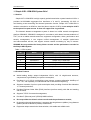
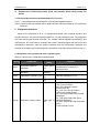
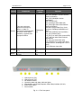
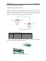
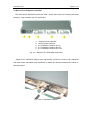
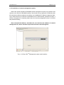
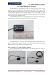
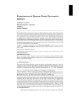
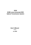
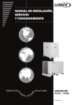
Simple 21E1-155M-SDH
User Manual
Simple 21E1-155M-SDH
Single-Board SDH Optical Transmission System
V1.1
Jan. 2005
User Manual V1.1
Page 2 of 19
Contents
1. Simple 21E1-155M-SDH System Brief ------------------------------------------------------------------ 4
1.1 Outline------------------------------------------------------------------------------------------------------ 4
1.2 Product Features ---------------------------------------------------------------------------------------- 4
1.3 Technical Specifications and Standards (ITU-T series)---------------------------------------- 5
2. Equipment Interface---------------------------------------------------------------------------------------- 5
2.1 Equipment running state and alarm indicator lights -------------------------------------------- 5
2.2 Control and Auxiliary Service Interfaces ---------------------------------------------------------- 8
2.2.1 EOW (Engineer Order Wire) interface ------------------------------------------------------ 8
2.2.2 Serial network management and user channels ----------------------------------------- 9
2.2.3 Ethernet NMS interface (NMU) --------------------------------------------------------------- 9
2.3 Main service and power interfaces --------------------------------------------------------------- 10
3. Network Applications --------------------------------------------------------------------------------------- 12
3.1 Point to Point network-------------------------------------------------------------------------------- 12
3.2 Short Line network ------------------------------------------------------------------------------------ 12
4. System Installation and Operation ------------------------------------------------------------------- 12
4.1 Equipment installation-------------------------------------------------------------------------------- 12
4.1.1 Unpacking ---------------------------------------------------------------------------------------- 12
4.1.2 Equipment installation------------------------------------------------------------------------- 12
4.1.3 Electrical installation--------------------------------------------------------------------------- 13
4.1.4 Equipment grounding ------------------------------------------------------------------------- 13
4.1.5 Installation of network management system -------------------------------------------- 15
4.2 System commission ---------------------------------------------------------------------------------- 16
4.3 Network management test -------------------------------------------------------------------------- 17
4.4 E1 tributary protection switch ---------------------------------------------------------------------- 17
5. Technical Parameters -------------------------------------------------------------------------------------- 17
5.1 Mechanical dimensions------------------------------------------------------------------------------ 17
5.2 Environmental requirements ----------------------------------------------------------------------- 17
5.3 Interface features-------------------------------------------------------------------------------------- 18
5.3.1 STM-1 optical interface ----------------------------------------------------------------------- 18
5.3.2 E1 tributary interface -------------------------------------------------------------------------- 18
5.3.3 Engineer Order Wire (EOW) interface ---------------------------------------------------- 18
5.3.4 Serial NMU (RS-232) interface ------------------------------------------------------------- 19
5.3.5 Ethernet NMU (RJ-45) interface (optional) ---------------------------------------------- 19
5.3.6 Timing mode------------------------------------------------------------------------------------- 19
User Manual V1.1
Page 3 of 19
Table index
Table 2-1 Simple 21E1-155M-SDH indicating lights .............................................................. 5
Table 2-2-1 EOW telephone interface.................................................................................... 8
Table 2-2-2 RS232 serial interface definition (RJ-45 end) ..................................................... 9
Table 4-2-1 Recommend measure instruments ................................................................... 17
Table 5-3-1 Technical indicators of STM-1 optical interface ................................................ 18
Table 5-3-2 E1 tributary interface......................................................................................... 18
Table 5-3-3 EOW interface .................................................................................................. 18
Table 5-3-4 Serial NMU ....................................................................................................... 19
Table 5-3-5 Ethernet NMU ................................................................................................... 19
Figure index
Fig. 2-1-1 The front panel....................................................................................................... 6
Fig. 2-1-2 The indicators of the front panel ............................................................................ 7
Fig. 2-1-3 The NE address switch .......................................................................................... 7
Fig. 2-2-1-1 EOW cable ......................................................................................................... 8
Fig. 2-2-1-2 EOW card ........................................................................................................... 8
Fig. 2-2-2 Serial interface structure ........................................................................................ 9
Fig. 2-3-1 Simple 21E1-155M-SDH back panel ................................................................... 10
Fig. 2-3-2 E1 tributaries interface ......................................................................................... 10
Fig. 2-3-3 the cable for 4xE1 ................................................................................................ 11
Fig. 2-3-4 E1 cable pin-out................................................................................................... 11
Fig. 3-1 Point to Point Network............................................................................................. 12
Fig. 3-2 Simple Chain Network............................................................................................. 12
Fig. 4-1-4-1 GND Jumpers ................................................................................................... 14
Fig. 4-1-4-2 System grounding............................................................................................. 14
Fig. 4-1-5 Easy SDHTM Management system main interface ............................................... 15
User Manual V1.1
Page 4 of 19
1. Simple 21E1-155M-SDH System Brief
1.1 Outline
Simple 21E1-155M-SDH is a high capacity optical transmission system based on ASICs. It
provides 2x155.52Mb/s aggregate line interfaces of A and B, possessing VC-3/VC-12
non-blocking cross-connecting and channel protection function. Simple 21E1-155M-SDH is
used as a terminal or an ADM in a short line (less or equal to 5 NEs); it can multiplex 21xE1
to the optical line port at most. It dose not support the ring network.
The Network element management system is based on unified network management
platform SDHNMS. SDHNMS is designed in accordance with related recommendations of
ITU-T, so as to realize network resources, equipment configuration, alarm, performance and
security management; it can support unified management of multiple optical-route
non-interconnected sub-net, and support remote network monitoring by way of Internet.
SDHNMS do not provides the history Alarm records and the performance records for
the Simple SDH System.
Table 1-1 SDH system
No.
Model
Product Description
1
OS155S8J
Simple 8E1-155M-SDH
2
OS155S16J
Simple 16E1-155M-SDH
3
OS155S21J
Simple 21E1-155M-SDH
4
OS155S42J
Simple 42E1-155M-SDH
5
OS155S63J
Simple 63E1-155M-SDH
6
OS8614
SDH optical transmission system Rack
1.2 Product Features
z
World leading design adopts independent ASICs, with 1U single-board structure,
compactness, high reliability, low power consumption;
z
Provides 63 x 63 VC12 non-blocking cross-connect, supports tributaries Add/Drop of
1~21 x E1, with capability of unidirectional and bi-directional multiplexing;
z
Supports networks of point to point and simple chain providing functions like tributaries
1+1 channel protection;
z
Provides Engineer Order Wire (EOW) interface (two-line model), with dial and meeting
call functions;
z
Supports TCP/IP for network management;
z
Provides F (Ethernet) and f (RS232) NMS interface;
z
Do not provides the historic alarm records and the performance records;
z
By changing the optical transceiver, it supports ultra-long distance (≤80km), long distance
(≤50km) and short distance (≤30km) transmission;
z
Equipment adopts natural wind heat emission, with stable and reliable work.
User Manual V1.1
Page 5 of 19
Supports the Free-Running timing mode, the standard G.813 timing modes are
absent.
z
1.3 Technical Specifications and Standards (ITU-T series)
G.703 Physical/electrical characteristics of hierarchical digital interfaces.
G.823 Control of jitter and wander within digital networks which are based on the 2048 kbit/s
hierarchy.
2. Equipment Interface
Simple 21E1-155M-SDH is a 19’‘-1U single-board design, with complete functions and
compact structure, can be conveniently installed on 19’‘wide equipment rack. The equipment
can meet shock, heat emission and EMC, etc. multiple national standard specifications and
requirements. The front panel is arranged with various indicating lights and the control and
management interfaces; while the power interfaces and the transmission interfaces are
focused on the back panel of the equipment. Description of the front panel is shown in Fig. 2-1.
2.1 Equipment running state and alarm indicator lights
Table 2-1 Simple 21E1-155M-SDH indicating lights
Name
Paraphrase
Effective
status
Remarks
PWR
Equipment power-on
indication
Green light is
on
Switch disconnected/power
invalid/reverse connection of
polarity/blowout
WORK
Equipment operation
indication
LOS1
Optical port A signal LOSS
Flashing represents a LOF
LOS2
Optical port B signal LOSS
Green light is
flashing
Red light is
on
Red light is
on
UALM
Equipment urgency alarm
Red light is
on
Flashing represents a LOF
LOS ( Loss of Signal)
LOF (Loss of Frame)
MS_EXC (Multiplex Section
Excessive Error)
AU_LOP (AU Loss of Pointer)
LOM (Loss of Multi-frame)
HP_PLM (High Order Path Payload
Mismatch)
HP_TIM (High Order Path Trace
Identifier Mismatch)
HP_EXC (High order Path Excessive
Error)
TLOS (Tributary Loss)
User Manual V1.1
Name
DALM
E1ALM
BUSY
Page 6 of 19
Effective
status
Paraphrase
This end equipment
appears non-urgency
alarm, or alarm or
performance deterioration,
or branch circuit failure
caused by opposite end
equipment failure
Red light is
on
Lights up when any of E1
Loss
Lights up when EOW
ringing
Red light is
on
Green light is
on
1.
2.
3.
4.
5.
6.
7.
Remarks
MS_AIS (Multiplex Section AIS)
MS_RDI (Multiplex Section Remote
Defect Indication)
MS_DEG (Multiplex Section
degraded)
AU_AIS (AU AIS)
HP_AIS (High Order Path AIS)
HP_RDI (High Order Path Remote
Defect Indication)
EXCEED (High Order Error Code
Overrun, including B1/B2/B3/out of
limit)
TU_LOP (Tributary loss of pointer)
TU_AIS (Tributary AIS)
LP_RDI (Low order Path channel RDI)
LP_PLM (low order Path Payload
Mis-match)
LP_AIS (Low Order Path AIS)
LP_EXCEED (Low Order Path Error
Code Overrun, including BIP-2 out of
limit)
TAIS (Tributary input AIS)
Optical port A (FC);
Optical port B (FC);
NE address switch;
Operating state and alarm indicator lights;
Management and EOW (Engineer Order Wire) interface (RJ-45);
Alarm mute switch.
Power switch.
Fig. 2-1-1 The front panel
User Manual V1.1
1.
2.
3.
4.
5.
6.
7.
8.
9.
10.
11.
Page 7 of 19
PWR Operating indicator;
WORK Operating indicator;
LOSA Signal loss of optical port A, it also represents a LOF when flashing;
LOSB Signal loss of optical port B, it also represents a LOF when flashing;
UALM Urgent alarm indicator;
DALM Non-urgent alarm indicator;
E1ALM Signal loss of E1tributary;
BUSY EOW call indicator.
EOW Engineer Order Wire interface (RJ-45);
RS232 NMS & User transparent serial interface (RJ-45);
NMU Ethernet network management interface (RJ-45).
Fig. 2-1-2 The indicators of the front panel
In SDH system, for the network management, each equipment should take an inherent
hardware address. The address is set by the switch manually. The coding method is simple
BCD, while the address could be “00”~”99” in decimal.
EXP: NE Address=01.
Fig. 2-1-3 The NE address switch
User Manual V1.1
Page 8 of 19
2.2 Control and Auxiliary Service Interfaces
2.2.1 EOW (Engineer Order Wire) interface
Simple 21E1-155M-SDH equipment adopts standard 2-line telephone set as EOW
telephone, whose cable that connected to equipment end is tailor-made: one end is RJ-11
connection telephone set; another end is RJ-45 connection Simple 21E1-155M-SDH
equipment. The interface definition is as shown in the following Figure.
Fig. 2-2-1-1 EOW cable
Table 2-2-1 EOW telephone interface
No.
PIN1~3
PIN4
PIN5
PIN6~8
Definition
Remarks
Not connected
TIP
RING
Not connected
The EOW card is used to provide the Order Wire function. It would be installed inside
Simple 21E1-155M-SDH after the client has ordered it.
Fig. 2-2-1-2 EOW card
User Manual V1.1
Page 9 of 19
2.2.2 Serial network management and user channels
Simple 21E1-155M-SDH uses the same RJ-45 socket to lead out serial NMS (Network
Management Station) and user serial interface, and uses dedicated serial interface cable: two
ends are DB9 plugs; another end is RJ-45 to connect Simple 21E1-155M-SDH equipment.
The cable’s linear ordering structure is as shown in the following Figure.
Fig. 2-2-2 Serial interface structure
Table 2-2-2 RS232 serial interface definition (RJ-45 end)
No.
Definition
PIN1
PIN2
Data-IN
Data-OUT
PIN3
RSNM-LINK
PIN4
PIN5
PIN6
PIN7
PIN8
GND
RSNM-IN
RSNM-OUT
Remarks
Serial data output
Serial data input
Serial network management connection
indication
Not connected
Not connected
Signal ground
Serial network management channel input
Serial network management channel output
2.2.3 Ethernet NMS interface (NMU)
Apart from providing RS232 serial NMS port, it is also recommended to use Ethernet NMS
port. The equipment provides NMS port on the front panel, which is used for connecting NMS.
While connect to a NIC (Network Interface Card), it uses a standard UTP crossover cable
(CAT-5); while connect to an Ethernet switch, it uses a straight-through cable.
User Manual V1.1
Page 10 of 19
2.3 Main service and power interfaces
The main service interfaces include two STM-1 optical ports and 21xE1 tributary electrical
interface. J type contains only one optical port.
1.
2.
3.
4.
5.
~220VAC power interface;
-48VDC power interface;
8 x E1tributary interface (#1~8);
8 x E1tributary interface (#9~16);
8 x E1tributary interface (#17~21).
Fig. 2-3-1 Simple 21E1-155M-SDH back panel
Simple 21E1-155M-SDH adopts 2mm high-density connector to lead out E1 tributaries
from back panel; description and annotation of related E1 tributary interfaces are shown in
following Figure.
Fig. 2-3-2 E1 tributaries interface
User Manual V1.1
Page 11 of 19
Fig. 2-3-3 the cable for 4xE1
Blue #1 E1 output
Red #1 E1 input
Pink #2 E1 output
Brown #2 E1 input
Gray #3 E1 output
White #3 E1 input
Yellow #4 E1 output
Green #4 E1 input
Fig. 2-3-4 E1 cable pin-out
STM-1 optical interfaces of Simple 21E1-155M-SDH are in two groups, located at the right
side of back panel; the interface is SC, the client should declare before ordering if SC is
needed. Simple 21E1-155M-SDH is equipped with FC interfaces.
The DC power interfaces of Simple 21E1-155M-SDH adopt three-line binding posts, used
for access-48VDC and PGND (protected ground), located at the left side of the Back Panel.
User Manual V1.1
Page 12 of 19
3. Network Applications
3.1 Point to Point network
The default application of Simple 21E1-155M-SDH is point-to-point.
Fig. 3-1 Point to Point Network
3.2 Short Line network
Simple 21E1-155M-SDH supports the simple chain network which contains 5 NE at most.
Fig. 3-2 Simple Chain Network
4. System Installation and Operation
4.1 Equipment installation
4.1.1 Unpacking
The operator should check the completeness of equipment packaging, possible transport
damage of equipment, and check correctness of equipment model and completeness of parts
according to the Packing List. In case of severe defection, installation should be immediately
stopped, and should contact the supplier.
4.1.2 Equipment installation
Simple 21E1-155M-SDH should be installed on 19 inch standard rack. Using 4 M6×12
bolts and through 4 mounting holes at both sides of equipment front panel, fix the equipment
User Manual V1.1
Page 13 of 19
on the rack. The equipment adopts natural wind cooling. In case of installation of multiple
equipments, it should keep upward/downward spacing of at least 1U for the equipment. Single
equipment can also keep flat on the desktop, but gapless stacking of multiple equipments is
strictly forbidden.
4.1.3 Electrical installation
z
The power switch must be set to OFF before power on.
z
The supply voltage is -48VDC, -36VDC~-72VDC is tolerable. Out range voltage
might result in equipment damage. Please verify the voltage before connecting.
z
Connect the power supply to the equipment. The reverse connection of –48VDC and
GND is forbidden. It will result in the damage of internal power module.
z
Connect E1 cable, note the impedance matching. Within Simple 21E1-155M-SDH, it
only provides 75Ω interface, the user should declare before ordering if 120Ω
connection is needed.
z
Connect optical interface. During the BER testing of tributary, FC/SC optical jumper
can be used to achieve self-loop of optical port, connect TX of port A to RX, and
connect RX of port B to TX.
z
Connect equipment NMU interface and NMS with UTP crossover line, or connect
Simple 21E1-155M-SDH serial-port to the NMS serial-port with serial cable.
z
Connect EOW telephone set to 21E1-155M-SDH EOW interface.
z
After connection of various cables, they must be fixed in cable slot with the belt, to
avoid damage.
z
Do not overexert in plug and pull of the E1 adaptor, in avoid of pins damage.
z
If any fault exists, please contact the supplier.
4.1.4 Equipment grounding
As compactable equipment, the “ground” is distinguished GND from PGND; when the
equipment works normally, GND and PGND should be connected to the earth ground. PGND
grounding resistance should be less than 4Ω, grounding cable’s profile area should be no less
than 6mm2, so as to attain various electrical indicators and provide necessary conditions for
safe and stable operating.
Notes for the operator:
1. The Equipment case has been jointed with PGND bolt on the back panel
inherently;
2. In the default factory mode, the E1 signal ground is connected to GND; if it is
needed to be changed to PGND, the operator should open the equipment case
and make the jumper changing manually, please see the following Fig.;
3. It is recommended for the user to connect PGND with the earth ground.
User Manual V1.1
Page 14 of 19
Fig. 4-1-4-1 GND Jumpers
In Simple 21E1-155M-SDH, the Earthing mode is determined by the jumper J14 and J2.
In the default mode, EGNG (the signal ground of E1) is short with GND (the power ground),
if it is necessary to short with PGND (the protect ground), the jumper should be changed.
Recommend schematic of System Grounding:
Fig. 4-1-4-2 System grounding
User Manual V1.1
Page 15 of 19
4.1.5 Installation of network management system
Before the operator install the SDHNMS network management system, the operator must
read the user manual of SDHNMS carefully. One should set up equipment IP address (each
NE should have different address) according to pre-established IP address assignment plan.
Log in after the start-up of software, the default account is Administrator, password is empty. If
security management is required, please enter into security management menu for account
and password setting.
Note: the default IP address: 192.168.2.155, one should set the address of network
management PC, which should be kept within the same network segment.
Fig. 4-1-5 Easy SDHTM Management system main interface
User Manual V1.1
Page 16 of 19
4.2 System commission
Safety Requirement
Optical interface
In order to ensure the personnel safety during the project contacting and using laser,
following rules must be observed when operating the optical equipment:
z
z
z
z
Optical fiber should be carefully kept and cleaned; and before its connection with
adapter, the connector should be covered to avoid pollutions.
The operator must be fully trained.
Before the system power off, do not look at the connector of the optical fiber straightly.
Do not bend the fiber with bending radius less than 30mm.
Power interface
The input power voltage of this series product is the standard industrial voltage
(48V±10%)
The commission can be defined as two stages: single-machine and network commission.
First of all, the single-machine checking should be completed successfully. A clear network
structure is required for network building, which should indicate connection relationship
between the NEs, as well as the NE name, IP address list, EOW number list, E1 routing list
and network clock synchronous plan. The E1 tributaries configuration of the Ethernet-bridge
and the password list for the network management are also required.
The operator should have the qualification of Telecom Engineer. He/she is also required to
familiar with equipment maintenance, Network Construction and Network Management, as
while as the security regulations. After the installation of the system (including network
management system) is completed, the operator must follow these procedures:
z
Visual checking
z
Power connection checking
z
Optical interface measurement
z
Electrical interface measurement
z
Clock precision measurement
z
EOW system testing
z
Network management system testing
z
BER (bit error rate) continuous testing
In order to realize test of various performance indicators, following table provides a table of
recommended instruments, the operator can also choose compatible types from different
vendors.
User Manual V1.1
Page 17 of 19
Table 4-2-1 Recommend measure instruments
Measuring instruments
Types
SDH analyzer
Anritsu MP1570A1
SDH/PDH analyzer
HP37718C
Optical power meter
TFC200
Variable optical pad
MN9611A
Multi-meter
BY1935
4.3 Network management test
The SDNNMS system shall be established after the software installation and the hardware
connection are completed. The SDHNMS system implements the configuration of a Simple
21E1-155M-SDH, it also gives the alarms and performance records except the historic
records.
4.4 E1 tributary protection switch
Evaluation switch request:
Alarms: LOS/LOF/LOM/AU-LOP/MS-AIS/AU-AIS/HP-AIS.
Performance: MS-EXC (10-3)/MS-DEG (10-6).
When the Bidirectional transmission condition is available, the system determines the
switching from the failure optical port to the normal one by compare the alarm or the
performance evens. All the E1 tributaries involved will be switched to the other optical port.
5. Technical Parameters
5.1 Mechanical dimensions
Dimensions: 481mm (L) x 305mm (W) x 44mm (H), (contains the handle edges)
Weight: 3.76Kg
5.2 Environmental requirements
Power supply: -48 VDC±10%
Fully equipment power consumption: 10W±10%
Operating temperature: 0°C~45°C
Humidity: ≤90% (free from condensing)
Atmospheric pressure: 70~106 Kappa
Storage temperature: -20°C ~70°C
Ambient air: free from corrosive gas and soluble gas, or dust nuisance, and without strong
electromagnetic field in the vicinity
User Manual V1.1
Page 18 of 19
5.3 Interface features
5.3.1 STM-1 optical interface
Table 5-3-1 Technical indicators of STM-1 optical interface
Bit Rate
155.520Mb/s±4.6ppm
Standard
ITU-T G.957/G.958
Optical fiber
Work wavelength
Relay-free
transmission
range
ITU-T G.652/G.653, single mode
1310nm (1550nm is optional)
50Km (70~100Km transmission distance available,
the user should declare before ordering)
Sensitivity
Better than -36dB
Connector
FC (SC is optional, the user should declare before
ordering)
Interface
S-1.1
5.3.2 E1 tributary interface
Table 5-3-2 E1 tributary interface
Bit Rate
Encoding
Standard
2.048Mb/s±50ppm
HDB3
ITU-T G.703
Connector
2mm high density connector
Impedance
75Ω non-balanced (120 Ω balanced is optional)
Jitter
performance
Comply ITU-T G. 823
5.3.3 Engineer Order Wire (EOW) interface
Table 5-3-3 EOW interface
Bit Rate
64Kb/s
Signaling mode
Dual tone multi-frequency dialing mode
Ring frequency
450Hz
Ring mode
Loudspeaker
NE address range
00~99
Interface
RJ-45
User Manual V1.1
Page 19 of 19
5.3.4 Serial NMU (RS-232) interface
Table 5-3-4 Serial NMU
Bit Rate
Interface
19200b/s
RJ-45
5.3.5 Ethernet NMU (RJ-45) interface (optional)
Table 5-3-5 Ethernet NMU
Bit Rate
Mode
Interface
10/100M
Full/half duplex auto-negotiation
RJ-45
5.3.6 Timing mode
Simple 21E1-155M-SDH supports free-run timing mode.