1
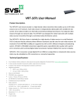
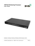
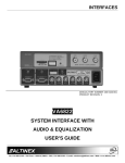
ATR-‐201 User Manual Product Description-‐ The ATR201 Audio Transceiver is an audio-‐over-‐IP solution that both sends and receives two-‐channel balanced or unbalanced audio over IP. Simply connect a balanced audio input into the IN port and it’s converted to IP packets that are switchable and routable just like data or voice. The balanced audio output receives an audio-‐over-‐IP stream and decodes to analog while preserving audio -‐fidelity. Perfect for point-‐to-‐point or point-‐to-‐multi-‐point audio delivery, the ATR201 provides audio matrix switching and distribution using the same control options as SVSi’s Networked AV video switching and distribution solution. With two auto-‐sensing gigabit Ethernet ports, units can be stacked to deliver low-‐latency multi-‐channel audio over a house network or a physically separate network. One Ethernet port is POE for use with a POE switch, eliminating the need for an external power supply. An audio matrix with any number of inputs and outputs can be constructed with the ATR201. Since control is the same as for voLANte’s video matrix, video and audio matrices can be combined and routed using the same controller for the ultimate in digital media distribution. Technical Specifications-‐ Audio Input: 2-‐channel user selectable balanced or unbalanced audio (1x 5-‐pin phoenix connector) Audio Output: 2-‐channel balanced audio (1x 5-‐pin phoenix connector) 2-‐channel unbalanced audio (headphone jack) Sample Frequency: 48-‐kHz, 44-‐kHz, 32-‐kHz Sampling Depth: 16-‐bit per channel Latency: 20-‐msec (excluding network propagation) Network: 1x RJ-‐45 auto-‐sensing gigabit Ethernet switch port – POE 1x RJ-‐45 auto-‐sensing gigabit Ethernet switch port Network protocols: multi-‐cast, unicast, IGMP v2, IPv4, layer-‐2 and layer-‐3 switch compatible Power: 5W max (either POE or 2-‐pin phoenix connector) Dimensions: 4″₺ x 4.5″₺ x 1.25″₺ Weight: 1 lb Warranty: 2-‐year Front of ATR-‐201 1.) 2.) 3.) 4.) Power Reset Button RJ-‐45 Auto-‐Sensing Gigabit Ethernet Switch Port RJ-‐45 Auto-‐Sensing Gigabit Ethernet Switch Port w/ POE Power Supply Connector (Power Supply Sold Separately) Rear of ATR-‐201 5.) 6.) 7.) 8.) LED Indicator Lights Input Phoenix Connector (5-‐pin) Output Phoenix Connector (5-‐pin) Headphone Jack Application Examples Set-‐Up and Installation Step 1: Download the Software Each ATR201 ships with an auto-‐IP address in the range of 169.254.xxx.xxx with netmask 255.255.0.0. Please download SVSi’s Conductor NetLite configuration software, free-‐of-‐charge from the Resources page. The host machine running Conductor NetLite must have a unique 169.254.xxx.xxx IP address assigned to its network interface connection to be able to auto-‐discover and communicate with the ATR201. After discovery, a static IP address can be assigned or a DHCP server used to define the unit’s IP address. Audio streams can be assigned to your device through NetLite or SVSi’s Conductor VDC108 or VDC208 hardware controller. The ATR201 does not ship with a wall-‐wart power supply since it is capable of POE power. Please contact your local reseller if POE is not available and an external power supply is required. Step 2: Install the software After the download completes, double-‐click the downloaded file to start the installation. Follow the prompts to install NetLite and associated Add-‐Ons. Step 3: Wire your Devices together Follow the below wiring diagram during initial setup to insure first time success. You can add additional devices to what is shown on the diagram, or include a switch. However, if the switch is improperly configured for SVSi products, problems can occur. If you have a pre-‐configured switch from SVSi, simply attach your devices. Add your computer into the network either via a port on the switch, or by attaching to one of the SVSi devices. Diagram: Blue – Network, Black – Video Step 4: Configure your computers IP Address SVSi equipment comes default with an IP Address of 169.254.XX.XXX. Your computer MUST have an IP Address in a similar range. To do this in Windows 7: 1. Open network and sharing center. 2. Choose “Change Adapter Settings” on the Left hand side of the screen. 3. Locate the appropriate adaptor in your list, and go to it’s properties (right-‐click, Properties) 4. Choose TCP/IPv4 and Select Properties. 5. Select “Use the following IP Address” A. Set the computer IP Address to “169.254.20.101” B. Set the subnet mask to “255.255.0.0” C. Select OK. 6. Exit out of the Network and Sharing Center. Step 5: Run Conductor Netlite Navigate to the install location of your conductor NetLite software – by default this is START>All Programs > Conductor NetLite. Start the Program. Step 6: Add devices to system 1. With NetLite Running: A. Select “System Admin” B. Select “Add” On Right hand side of the window C. Select “Auto Discover Devices” 2. After Discovery is complete (If Auto Detect did not detect anything – Refer to the Advanced Discovery Methods Appendix at the end of this document.) A. Check the box next to each device you wish to Add, or choose Select All B. Click on “Add Selected” and then “Close” You have successfully added your devices to your system! Step 7: Organization and Setup of Devices 1. Close the System Admin Window, and open the Matrix View. 2. Starting with Transmitters in turn do the following: A. Double-‐click the device’s name to bring up the Properties B. On the Basic Settings Tab: i. Change the Name to something friendlier (I.E. Cable Box 1 or Bob’s Computer) C. On the Advanced Tab: i. Slide the Image Quality and Motion Quality Faders all the way to the right. This will insure the highest image quality. If you need to lower the bandwidth used by a transmitter later on, this is where you would accomplish that. ii. Change the Stream Number – Valid numbers are 1 through 255. Organize the stream numbers as you see fit. D. On the Copy Protection Tab i. Read the Statement and decide to allow or block copy protected content. E. On the Network Tab i. Change the IP Address (if needed) to the appropriate IP Address (usually supplied by your network administrator a. Click the box at the end of the IP Address field b. Choose “Use the following IP Address” c. Set your IP Address, Subnet Mask, and Default Gateway to their new values. d. Select OK ii. Make Sure all of the Media Port Options are Checked (advanced users can change this at a later date if needed) F. Select Apply. i. This will cause the Transmitters to Reboot, and take on their new IP Address. At this stage, you may lose communication with the device, as it’s IP address has changed. Continue changing all of the transmitters in a similar fashion until complete. 3. Starting with the First Receiver A. Double-‐click the device name to bring up the Properties for each Receiver in turn, and do the following: i. General Tab a. Change the Name of the Device b. Decide if you want to force Audio to Follow Video. If this option is not set, you can independently switch audio and video streams using advanced control options. ii. Serial Port a. If using the on-‐board RS-‐232 Port, configure your port settings as needed. Testing of RS-‐232 Commands is covered later in this document iii. Network a. Configure the IP Address of the Receiver. Follow the same steps as setting the IP Address for the Transmitters. iv. Select Apply a. At this point, you may lose connectivity to the device as it resets its IP Address. Continue to the rest of the devices before changing your laptop’s IP Address. 4. If Needed – Change your laptop’s IP Address. A. If you changed the IP Address of the Transmitters and Receivers to something other than default, then you will need to reset your computers IP Address to match. Step 8: Working with the Matrix. Your matrix should now look similar to the matrix pictured below. There are several modes for each transmitter and receiver that will help you setup your video matrix. To change a device’s mode, do the following. 1. Double-‐click on the Transmitter or Receiver. 2. Click on the drop-‐menu to the right of the device’s name input box. 3. Select the Desired Mode. In Host Play, or Local Play (explained below) you must also choose one of the playlists. The Various Modes for each device are as follows. 1. Transmitter A. Host Play – Each transmitter has on-‐board memory for storing a various amount of still image files. These can be used to display a slideshow to multiple receivers in a similar fashion to Live Play. This will turn off the attached video sources video, and begin playing back the slideshow B. Live Play – This is the video coming from the attached device C. EmCast – An Emergency Messaging system that can send message to all receivers in the network. 2. Receivers A. Local Play – The same thing as host play, but is only available on the receiver B. Live Play – Plays the live stream coming from a transmitter. Changing the Matrix 1. Start by attaching a video source to an available Transmitter. 2. Verify your transmitter is in Live Play Mode 3. Verify your desired receivers are in live play mode as well. 4. Using the Radio Buttons, click the cross-‐point for the Transmitter/Receiver combination – as shown below. 5. The Background will turn Yellow. Continue attaching receivers to transmitters until you have made all of your connections. TIP: Start by attaching all of your Receivers to one Transmitter to verify on all devices that streaming is working 6. Select the “Take” Button. This will make the changes in your matrix, and the background for all checkboxes changed will turn blue. Troubleshooting: Auto-‐Detect Failure If Auto-‐Detect failed to discover your attached devices, it is most likely a network configuration issue. Please try the following steps to resolve the problem: 1. Try to search by MAC Address. A. Locate the sticker on the bottom of the device that has the mac address. In the discovery window, select “find by Mac Address”. Enter the MAC address and search. B. If the device is found, determine the units IP Address, and if it has a different IP Address from the default, you may need to change the computers IP address to be in the same range. After changing the computers IP Address, change the devices IP address to a corrected one and continue. 2. If Searching by MAC address FAILS: A. Start by disabling every network adaptor on your computer, except for the one connected to the SVSi system. Attempt to Auto Discover Again. B. If that fails, do the following: i. On the conductor NetLite main screen select “conductor” and then “options” ii. In the network section of the window, choose “enable adapter binding” iii. Specify the correct adapter in the drop down menu iv. Select OK v. Attempt Auto Discovery Again 3. When trying to troubleshoot a SVSi System, Wireshark can be a powerful tool to help track down network errors, problems, or a communications breakdown. It is an incredibly powerful and flexible tool with many ways to utilize it during troubleshooting. If you are having problems with your network, you may want to download it and follow the guides to help you track down and resolve the problems. Download here – www.wireshark.org/ WireShark is a packet sniffing tool, it can be used to track traffic across your network. You can add an IP filter in to track packets going to/from a specific IP address. More details can be found on WireShark’s website. 4. If all of the above fail A. Contact Technical Support for additional help. LocalPlay screen showing with live video source: Confirm that encoder and decoder are not connected through a network. If connected through a network, please consult IT administrator and the SVSi pre-‐implementation guide available at www.svsiav.com/downloads. Verify that both encoder and decoder are set to LivePlay in software and not LocalPlay or HostPlay. Verify that Power, DVI, and LAN lights on VRR104 are illuminated. Display shows only black screen: Verify that cable connecting encoder and decoder shows gigabit Ethernet connectivity with a 3-‐blink pattern on left LED on RJ-‐45 connector. Verify that video source is not putting out a black screen by default. If connected through a network, please consult IT administrator for multicast routing protocols for your network. Video present but no audio: Confirm that audio-‐over-‐DVI is enabled on both encoder and decoder in software if using embedded audio. Conductor Server and Conductor DiVAS have the ability to route the audio matrix different than the video matrix. Verify that audio for the decoder is not attached to a different or non-‐existent source in Server’s audio matrix. Attached network device unresponsive: Default bandwidth of video traffic is 25-‐Mbps and can overwhelm 10-‐baseT or 100-‐baseT devices. If such a device (third-‐party TCP/IP controller, IP camera, network printer, point-‐of-‐sale device, etc.) is connected, video traffic must be blocked from the port to which it connects. Blocking video traffic to specific ports can be done in Conductor NetLite or Server. Alternatively, the slower network device can be plugged into a layer-‐3 switch with IGMP-‐query capability to firewall the video traffic. Display shows “Unsupported Resolution” splash screen: SVSi does not support 480i resolution that some older DVD players and cameras output. Set output on video source to 480p, 720p, 1080i, or 1080p. Appendix A Color Codes in NetLite When looking at the matrix, colors are used to allow you to quickly glance and determine the status of all the attached devices. The following colors are used: ICONS: Green – Actively Online and Broadcasting/Receiving Red – Communication Lost Blue – Local/Host Play TEXT: Black – Display Detected or Valid Video Source Red – No Display Detected or No Valid Video Source Appendix B SVSi video networks can be controlled by several options: 1. Conductor NetLite – virtual matrix switching software for PC, free download from www.svsiav.com/downloads 2. Conductor DiVAS VDC108/208 – Conductor Server running on a dedicated Linux 2RU device with email notification and simplified ASCI control through serial or telnet 3. TCP/IP control by any third-‐party controller such as AMX, Crestron, Altinex, Extron, etc. Control modules for AMX and Crestron controllers are available from SVSi’s partner portal website Appendix C Using SVSi as a point-‐to-‐point video extender: 1. Connect the appropriate cable from a video source to DVI connector on encoder. The VMT105-‐D, VRT107C-‐D, and VRT107U-‐D models require digital video input on the DVI-‐D connector. The VMT105-‐I, VRT107C-‐I, and VRT107U-‐I support either analog or digital video input (but not both) through an appropriate cable. Note: all SVSi encoders support either embedded digital audio through the DVI connector or analog audio input through the 3.5-‐mm jack (but not both). Audio-‐over-‐DVI is disabled by default and must be enabled in Conductor NetLite, Server, or DiVAS software or the VDT111 Interface. 2. Connect a network cable from any one of the RJ-‐45 Ethernet ports on the encoder to a network port on a SVSi decoder. The maximum distance between network ports is 100-‐m. Network switches can be used to extend distances as needed in 100-‐m increments. 3. Connect the VRR104 or VRR204 decoder to a digital video port on the display (either DVI or HDMI) with appropriate cable. The VRR104 supports embedded digital audio-‐over-‐DVI and de-‐embedded analog audio from the dual RCA connectors. Both embedded digital and de-‐embedded analog audio signals can be accessed at the same time; however, audio-‐over-‐DVI is disabled by default and must be enabled in software before use. The VRR204 supports only embedded digital audio-‐over-‐DVI. Note: when using a computer monitor as display, audio-‐over-‐DVI must be disabled or image will be corrupted. 4. As soon as the decoder is powered up and all cables connected, the splash screen show below stored on the decoder will appear. If encoder and decoder are correctly connected, live video from the source will be displayed.