1
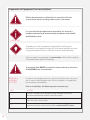
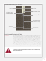
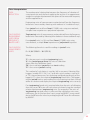
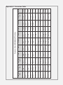
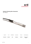
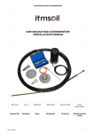
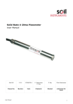
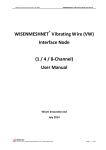
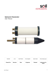
Man 106
STANDARD
VIBRATING WIRE
PIEZOMETER
User Manual
Soil Instruments Limited has an ongoing policy of design review and reserves the right to amend these specifications without notice.
Man106 - Vibrating Wire Piezometer - Standard - MN1114 - Rev1.2.0
1
What’s this manual about? This manual tells you about the Standard Vibrating
Wire Piezometer and how to use it to measure pore
water pressures in fully or partially saturated soil.
Who does this apply to?
Installers, field engineers and technicians who need
to acquire pore water pressure measurements in fully
or partially saturated soil.
2
Welcome!
Thank you for choosing the Standard Vibrating Wire
(VW) Piezometer.
This manual has been written to provide you with relevant
information and to guide you in best practice when using a
Vibrating Wire Piezometer in order for you to gain the most
from our product.
Please read this manual thoroughly before use to help avoid
any problems and keep it handy during installation.
Standard Vibrating Wire Piezometer
The Standard Duty Vibrating Wire Piezometer accurately
measures pore water pressures in fully or partially saturated
soil and is designed for pressure ranges from -50 to 4,000 kPa.
The small diameter piezometer is hermetically sealed and
combines in-built temperature compensation with an
integral thermistor for temperature monitoring and an
over voltage surge arrestor to offer protection from indirect
lightning strikes.
The transducer is fitted with either a low air entry sintered
steel or a high air entry ceramic filter and is manufactured
from high quality 316 grade Stainless Steel, providing
long-term stability and reliability.
A cone shaped nose piece is available for push-in installations.
3
Contents
PART I - OVERVIEW6
Introduction:8
Important Information8
Product8
Changes8
Warranty8
Disposal8
System Description:9
Things You Need to Know About the Vibrating Wire Piezometer
9
Features9
Benefits9
System Components10
Overview10
Standard Vibrating Wire Piezometer Components
11
PART II - VW PIEZOMETER PREPARATION GUIDE
12
Preparation of Equipment Prior to Installation
14
Removal and Assembly of Filter 14
Pre-Installation Base Reading15
PART III - VW PIEZOMETER INSTALLATION GUIDE
16
Standard Vibrating Wire Piezometer Installation Procedure
18
Drilling the Borehole18
Installing the Piezometer19
Borehole Installation19
Installation in Fill20
Installation of Heavy Duty Push-In Piezometer
20
Installation and Termination of Cable
21
Overview21
Installation in Trenches22
Termination of Cables23
4
PART IV - TEMPERATURE & PRESSURE EFFECTS & DATA REDUCTION 25
Effect of Temperature and Pressure
27
Temperature Change27
Effect of Barometric Pressure
28
Data Interpretation29
Data Reduction29
Calculating Engineering Units From Frequency Based Units 29
Calculation Using Period Units
29
Calculation Using Linear Units
30
Linear Unit Calculation Using a Polynomial Equation
30
PART V - APPENDICES31
Appendix A - Conversion Table
33
Appendix B – Troubleshooting Guide
34
Appendix C - Sample Calibration Certificate
36
Appendix D - CE Declaration
37
PRECISELY MEASURED
instrumentation and monitoring
5
Part I – Overview
6
Contents
This section contains the following topics.
TOPIC
Introduction:
Important Information
Product
Changes
Warranty
Disposal
System Description:
Things You Need to Know About the Standard Vibrating Wire Piezometer
Features
Benefits
System Components
Overview
Standard Vibrating Wire Piezometer Components
SEE PAGE
8
8
8
8
8
8
9
9
9
9
10
10
11
7
Introduction:
Important Information
The following symbols are used throughout this manual
WARNING
IMPORTANT
INFORMATION
TIP
QUESTION
! Important: Failure to adhere to the warnings in this manual
may result in network disruption and possible data loss.
Failure to observe the warning may result in injury, product
malfunction, unexpected readings or damage to the product
that may invalidate its warranty.
Tips give additional information that may be helpful when using
a Standard Vibrating Wire Piezometer.
8
PRODUCT
CHANGES
Soil Instruments Limited has an on-going policy of design review
and reserves the right to amend the design of their product and
this instruction manual without notice.
WARRANTY
Please refer to Soil Instruments Limited terms and conditions of
sale for warranty information. Batteries are a consumable item
and are excluded from any warranty.
DISPOSAL
Products marked with the symbol are subject to the
following disposal rules in European countries:
• This product is designated for separate collection at an
appropriate collection point
• Do not dispose of as household waste
• For more information, contact Soil Instruments Limited
or the local authority in charge of waste management.
System Description:
Things You Need to Know About the Standard Vibrating Wire Piezometer
FEATURES
• Small diameter
• Uses proven Vibrating Wire (VW) technology
• Manufactured from high grade 316 Stainless Steel
for extended operation
• In built temperature compensation
• Hermetically sealed
• Suitable for long-term monitoring
• No electronic components in sensor module
• Capable of measuring negative pore pressures to –50 kPa
• Fitted with thermistors for temperature monitoring
BENEFITS
•
•
•
•
•
•
Accurate, repeatable readings over long cable lengths
Long working life, long-term stability and reliability
Fast response to pressure changes
Design prevents case stresses from affecting readings
Over-voltage surge arrestor protects against electrical damage
Connecting cable is strong, screened and flexible
9
System Components
OVERVIEW
The piezometer comprises a porous tip element connected to a
Vibrating Wire (VW) Transducer. The transducer body is constructed
throughout from high integrity materials; the sensing wire, diaphragm
and anchor are enclosed in an independent unit. An electrical surge
protector is included in the design to prevent coil damage should
excessive voltages be induced into the connecting cable during
electrical storms.
The transducer consists of a rigid cylinder, sealed at one end by a
watertight bulkhead and at the other by a thin diaphragm which
serves as an elastic, force sensing member. A thin steel wire strung
between these two points is tensioned and firmly anchored during
manufacture. A coil/magnet assembly set at the mid-position on
the wire provides the means of exciting the wire into oscillation,
the frequency of which is dependent on wire tension.
Pore water pressure acting on the diaphragm causes it to deflect,
changing the tension of the wire and the resonant frequency.
The readout unit supplies an electrical pulse to the coil/magnet
assembly which plucks the wire, causing it to vibrate at its
resonant frequency.
The coil/magnet assembly acts as a pickup as the oscillations of
the wire through the magnetic field induce an alternating current
in the coil which is detected by the readout. The readout converts
the sinusoidal alternating voltage to a square waveform which may
easily be timed using a frequency oscillator. In this way the period
of oscillation may be accurately measured.
The relationship between a change in the period of oscillation and
the strain of the wire is non-linear. Basic readout units simply give a
reading in period units, which must be manually converted, to the
appropriate units by use of formulae. More sophisticated readout
units such as Soil Instruments ‘VWnote’ are programmable to give a
direct reading in the appropriate engineering units. ‘VWnote’ is also
able to store a series of readings in a non-volatile memory for future
transfer to a PC.
Please refer to Datasheets ‘RO-1-VW-NOTE Vibrating Wire Note’ and
‘RO-1-VW-READ Vibrating Wire Readout’ for details on Soil Instruments
Vibrating Wire handheld readouts.
10
Standard Vibrating Wire Piezometer Components
Cable
Stainless Steel housing
Porous
element
Watertight, flexible cable gland
Watertight, flexible
cable gland
Stainless Steel housing
Detachable
nose piece
Rubber washers
Water block
potting
Waterproof
connection block
VW transducer
Sensing wire
Coil/magnet
diaphragm
Porous element
Filter end piece
Nylon washer
11
Part II VW Piezometer
Preparation
Guide
12
Contents
This section contains the following topics.
TOPIC
Preparation of Equipment Prior to Installation
Removal and Assembly of Filter
Pre-Installation Base Reading
SEE PAGE
14
14
15
13
Preparation of Equipment Prior to Installation
Follow the precautions outlined in this manual at all times
to ensure the correct working order of your instrument.
WARNING
It is essential that the equipment covered by this manual is
handled, operated and maintained by competent and suitably
qualified personnel.
IMPORTANT
INFORMATION
To guide you in the competence required for installing each
instrument in our product range, Soil Instruments provide you with
a recommended skill level in all of our manuals and datasheets.
TIP
Soil Instruments recommend an intermediate skill level for installing
a Standard Vibrating Wire Piezometer.
The ceramic filter MUST be soaked in clean water for a minimum
of 24 HOURS prior to installation.
WARNING
REMOVAL &
ASSEMBLY
OF FILTER
As soon as the equipment arrives, check that all the necessary parts
are in correct working order, even if the installation is not going to
be carried out immediately.
Prior to installation, the following tasks are necessary:
STEP
14
ACTION
1
Locate a suitable clean container, large enough to immerse
the entire piezometer and fill with clean water
2
Unscrew the detachable nose piece containing the filter
from the main sensor body
3
Immerse the nose piece containing the filter upright in the
container of clean water and soak for a minimum of 24 hours
STEP
ACTION
4
Shortly before proceeding with the installation, immerse the
piezometer body in the same container of water and invert
to expel any air, repeat if neccesary to ensure that all the air
has been removed
5
Invert the detachable nose piece containing the filter
to expel any air and screw the nose piece back on to
the piezometer body, keeping both sections immersed
in the water during attachment
PRE-INSTALLATION
BASE READING
Please refer to Datasheets ‘RO-1-VW-NOTE Vibrating Wire Note’ and
‘RO-1-VW-READ Vibrating Wire Readout’ for details on Soil Instruments
Vibrating Wire handheld readouts.
It is necessary to establish a base reading for each instrument
prior to installation.
WARNING
STEP
ACTION
1
Ensure that the piezometer is totally immersed in clean water to a
depth of a few centimetres only and is shielded from direct sunlight
2
Connect the instrument cable to Vibrating Wire Readout such
as ‘VWnote’ or ‘VWread’ and record the reading in frequency
or period units
3
Wait for 15 minutes for the transducer to adjust to the temperature
of the water and repeat the reading operation.
A value identical to the first reading indicates that the transducer
has adjusted to the water temperature.
TIP
4
Continue reading (if necessary) until stability is observed
5
Record the reading with the current barometric pressure
and water temperature
15
Part III VW Piezometer
Installation
Guide
16
Contents
This section contains the following topics.
TOPIC
Standard Vibrating Wire Piezometer Installation Procedure
Drilling the Borehole
Installing the Piezometer
Borehole Installation
Installation in Fill
Installation and Termination of Cable
Overview
Installation in Trenches
Termination of Cables
SEE PAGE
18
18
19
19
20
20
20
21
22
17
Standard Vibrating Wire Piezometer Installation Procedure
Follow the precautions outlined in this manual at all times
to ensure the correct working order of your instrument.
WARNING
It is essential that the equipment covered by this manual
is handled, operated and maintained by competent and
suitably qualified personnel.
IMPORTANT
INFORMATION
To guide you in the competence required for installing each
instrument in our product range, Soil Instruments provide you with
a recommended skill level in all of our manuals and datasheets.
TIP
DRILLING THE
BOREHOLE
Soil Instruments recommend an intermediate skill level for installing
a Standard Vibrating Wire Piezometer.
A borehole with the diameter of 75 - 150mm is either driven into
soils using shell and auger drilling or into rock using rotary water
flush drilling.
Air flushing and subsequent entrapment of air in the ground
should be avoided.
WARNING
The sides of the borehole in the vicinity of the piezometer tip should
be free from mud cake and debris. If the hole requires casing, this
should be withdrawn to keep pace with the installing operation.
TIP
18
On completion of the borehole it is strongly recommended to flush
with fresh water to remove any silt or debris that may be present in
the borehole. A head of water will ease installation of the piezometer;
however this is not appropriate in highly impermeable soils.
If the borehole is completely dry add a little water to cover the
instrument during installation.
TIP
Installing the Piezometer
BOREHOLE
INSTALLATION
Place coarse clean filter sand through the water, ideally with a tremie
pipe and compact to the proposed base of the piezometer tip.
Allow a suitable amount of time for the sand to settle, particularly if
the water level is high.
When marking the proposed depth of the piezometer, make sure
you take into account the borehole casing above ground level.
WARNING
Mark the proposed depth of the tip on the piezometer cable using
coloured P.V.C. adhesive tape, remembering to take account of any
borehole casing remaining above ground level.
Just prior to installation measure the water level in the borehole.
Very carefully lower the piezometer down the borehole until the
tape mark coincides with the top of the casing.
Take a reading on the piezometer, allowing time for temperature
equilibrium to be established. Compare the calculated head of
water with the measured water level.
Comparing the calculated head of water with the measured water
level is a very useful operational test.
TIP
Place further filter sand until the tip is covered by at least 150mm.
If using a punner to compact the filter material, take extra
precaution not to damage the cable.
WARNING
19
Remember to allow time for the sand to settle as it is difficult to
remove surplus sand without causing considerable disturbance.
WARNING
A plug to prevent entry of grout into the filter should be placed in
the form of bentonite pellets, or alternatively balls of stiff bentonite
no larger than 50mm diameter, may be dropped through the water
and tamped into place.
Backfilling is completed to ground level with an impervious grout,
generally a bentonite-cement mix through a tremie pipe, positioned
above the bentonite plug and withdrawn as grouting proceeds.
If more than one instrument is being installed it is vitally
important to clearly identify the cables using colour coded
P.V.C. adhesive tapes.
WARNING
INSTALLATION
IN FILL
This is essentially similar to installation in shallow soil foundations.
In clay fill, the piezometer may either be placed in a sand pocket or in
direct contact with the fill material. This latter operation is performed
using a mandrel to form an impression into which the piezometer
is placed. In rock fill the tip should be surrounded by clean coarse
filter sand.
Installation of Heavy Duty Push-In Piezometer
IMPORTANT
INSTALLATION
INFORMATION
The push-in Piezometer is designed for pushing into soft soils using drill
rods either by hand or using the hydraulics of the rig. The Piezometer
should be monitored during the pushing process to ensure that
pressures do not exceed the calibrated range of the piezometer. Should
the pressures reach or exceed the calibrated range the process should
be stopped to allow the pressure to dissipate before continuing.
If the drill rods are to be removed then a bladed anti rotation rod with
a left hand/right hand threaded adaptor should be used. This will allow
the drill rods to be rotated clockwise and detached from the bladed
anti rotation rod. The left hand/right hand threaded adaptor will be
recovered with the drill rods for reuse. The filter tip should be saturated
prior to installation as per the standard piezometer.
See diagram of Installation by pusing into soft soils for more details.
20
Installation by Pushing Into Soft Soils
Borehole
Drill Rod
Piezometer Cable
Left/Right Hand
Threaded Adaptor
Anti-Rotation Blades
Anti-Rotation Rod
(1m or 2m Long)
Piezometer
Filter Housing
Installation and Termination of Cable
OVERVIEW
Connecting cable is laid in a trench deep enough to provide protection
from mechanical damage. In certain situations the cables may be run
in protective conduits or cast into concrete, however, great care should
be taken to protect cables at interfaces between such relatively rigid
conduits and flexible soil areas if this method is used. The choice of
suitable protection material surrounding the cable along the trench
length will depend on local factors, but in all cases should be fine grained
with a particle size less than 0.5mm and not contain any sharp particles.
Fine sand is preferable in free draining areas, but should be replaced by
screened silt or clay based soil where lower permeability is required.
Failure to use the correct protection material may result in piping
along the trench lines.
WARNING
21
You MUST use screened connecting cable and use an
electrical jointing kit, ensuring you follow the manufacturer’s
instructions precisely.
WARNING
INSTALLATION IN
TRENCHES
The screened connecting cable is compacted within the trench, ensuring
that it is protected by 150mm of stone-free material, normally sand, silt or
clay above and below the cable itself. Although sand is often the most
convenient to use; only silt clay or clay should be used where the creation
of a drainage path would be undesirable.
If the trench passes through an impervious clay core of an
embankment dam, additional cut-offs across the trench may
be necessary. If the trench is to be backfilled using rock fill or
coarse granular material, the thickness of the protective layer
over the cables should be increased to 250mm.
IMPORTANT
INFORMATION
The trench cable must be connected to the borehole cable by use of
a proper electrical jointing kit. It is strongly recommended to avoid any
cable joints, however if this is not possible, the same jointing kit must
be used.
The effectiveness of these joints largely depends on the care
with which the jointing operation is carried out.
WARNING
The cables should be laid loosely within the trench and snaked to
prevent any strain due to ground movements; in most cases a
wavelength of 3m and amplitude of 200mm should be sufficient.
In certain cases it may be advisable to separate the cables from each
other within the base of the trench. The cables should be looped on
crossing an interface where differential ground movements might
be anticipated and may also be looped at cable joints to avoid any
unnecessary stresses. The cables should be identified using coloured
P.V.C. tape applied at regular intervals.
The correct functioning of the instrument MUST be checked before
backfilling the trench.
22
Compaction of backfill should be carried out using only hand
operated equipment.
WARNING
It may be advisable to clearly mark out or survey the position of the
instrument trench, particularly if there is to be further excavation or
borehole drilling in the vicinity. A record of the trench position and
depth should be kept and pegged out.
TERMINATION OF
CABLES
The cables are normally terminated in multi-channel terminal units.
The terminal units have a hinged cover secured by two screws and
the cables enter through waterproof glands.
Please refer to Datasheet ‘RO TB-JB-TJ - Terminal and Junction Boxes’
for details on Soil Instruments terminal and junction boxes.
23
To wire the cables into a terminal unit, follow the step guide below.
STEP
1
ACTION
Unscrew and open the hinged cover
2
Unscrew the four fixing screws holding the terminal panel and
carefully remove it without straining the connecting leads
3
Prepare the cables by stripping and cutting back approximately
20mm of the outer insulation and screen
4
Remove the inner sheath and strip back 5mm of the
conductor insulation
5
Slacken the entry glands and insert the cables
6
Make connections to the terminal blocks
7
Re-tighten the glands to grip the cables
8
Replace the terminal panel and secure
9
Connect the readout unit to each instrument in turn to
check connections
Please refer to Datasheets ‘RO-1-VW-NOTE Vibrating Wire Note’
and ‘RO-1-VW-READ Vibrating Wire Readout’ for details on
Soil Instruments Vibrating Wire handheld readouts.
24
Part IV –
Temperature &
Pressure Effects
& Data Reduction
25
Contents
This section contains the following topics.
TOPIC
Effect of Temperature and Pressure
Temperature Change
Effect of Barometric Pressure
Data Interpretation
Data Reduction
Calculating Engineering Units From Frequency Based Units
Calculation Using Period Units
Calculation Using Linear Units
Linear Unit Calculation Using a Polynomial Equation
26
SEE PAGE
26
26
27
28
28
28
28
29
29
Effect of Temperature and Pressure
TEMPERATURE
CHANGE
The materials used in the construction of the transducer are carefully
chosen and controlled in order to reduce the effect of ambient
temperature changes on readings. In addition, the strain wire assembly
is evacuated when it is sealed during manufacture, which considerably
reduces internal air pressure on the diaphragm when the piezometer
is heated, which might give rise to false negative readings in extremes.
The significance of temperature change is always with respect to the
temperature difference between the current time and the time of the
pre-installation base reading. As a rule of thumb, installed temperature
changes of less than 10° C are not, for practical purposes, significant.
If large temperature changes are to be expected in the ground where
the piezometers are to be installed, then consideration must be given
to specifying the incorporation of a thermistor coil in each transducer,
or the separate installation of another temperature measuring device
in order to provide the temperature data required for corrections to
be applied.
WARNING
Temperature gradients across the unit, triggered by rapid changes
in ambient temperature will produce considerable reading error.
For this reason it is essential that pre-installation base readings are
only taken after sufficient time has been allowed for the transducer
to stabilise at the ambient temperature. Piezometers MUST be
immersed in shallow water and shaded from direct sunlight until
readings settle.
27
EFFECT OF
BAROMETRIC
PRESSURE
External pressure applied to the diaphragm of the transducer modifies
the wire tension and therefore its resonant frequency. Such a change
is used to determine the magnitude of the applied pressure.
Since the unit is evacuated and sealed during manufacture,
subsequent external variations in barometric pressure will cause a
differential force to act across the diaphragm which will affect the
tensioned wire proportionally.
The effect is most significant with thin diaphragms (low range units).
For example;
For a 50mH20 transducer, a ±10 millibar change in ambient
barometric pressure, (equivalent to 100 mm of water head),
relative to the encased pressure within the unit will modify
the reading by the equivalent of ±100 mm of water head,
even though the external water head to be measured
remains constant.
In such applications where such relatively small variations are considered
to be significant, correction of reading errors due to barometric pressure
changes should be applied respectively. For this purpose a note of
barometric pressure on the day of the pre-installation base reading is
required and also an accurate barometer must be available on site.
28
Data Interpretation
DATA
REDUCTION
The mathematical relationship between the frequency of vibration of
a tensioned wire and the force applying the tension is an approximate
straight line relationship between the square of the measured frequency
and the applied force.
Engineering units of measurement maybe derived from the frequency
based units measured by vibrating wire readouts in 3 traditional ways;
From ‘period’ units and from ‘linear’ (f2/1000) units using two methods;
a simple linear equation or a polynomial equation.
CALCULATING
ENGINEERING
UNITS FROM
FREQUENCY
BASED UNITS
‘Engineering’ units of measurement maybe derived from the frequency
based units measured by Vibrating Wire readouts in three traditional ways;
CALCULATION
USING PERIOD
UNITS
The following formula is used for readings in ‘period’ units.
From ‘period’ units (t x 107) and from ‘linear’ (f2/1000) units using
two methods, a simple ‘linear’ equation or a ‘polynomial’ equation.
E = K (10^7/P0^2 – 10^7/P1^2)
Where;
‘E’ is the pressure in resultant ‘engineering’ units,
‘K’ is the ‘period gauge factor’ for units of calibration
(taken from the calibration sheet)
‘P0’ is the installation ‘period’ base or ‘zero’ reading
‘P1’ is the current ‘period’ reading.
This method of calculation is used by Soil Instruments Vibrating Wire
Loggers (models RO-1-VW-1 or 2 and with serial numbers starting VL
or TVL) internal processors, for calculating and displaying directly on the
loggers LCD screen, the required ‘engineering’ based units. The loggers
require ‘period’ base or zero reading units for entering into their channel
tables to calculate and display the required ‘engineering’ units correctly.
If an ‘engineering’ based unit is required other than the units of calibration,
then the correct ‘K’ factor will have to be calculated using the standard
relationship between ‘engineering’ units. For example, if the units of
‘engineering’ required were in inches and the calibration units were
millimetres, we can find out that 1mm is equal to 0.03937”, so we would
derive the ‘K’ factor for inches by multiplying the ‘K’ factor for millimetres
by 0.03937.
29
CALCULATION
USING LINEAR
UNITS
The following formula is used for readings in ‘linear’ units.
E = G (R0 – R1)
Where;
‘E’ is the resultant ‘engineering’ unit,
‘G’ the ‘linear gauge factor’ for the units of calibration
(taken from the calibration sheet)
‘R0’ is the installation ‘linear’ base or ‘zero’ reading
‘R1’ is the current ‘linear’ reading.
Again the ‘linear gauge factor’ for units other than the units of calibration
would need to be calculated using the same principles as stated in the
last paragraph of the ‘period unit’ section.
LINEAR UNIT
CALCULATION
USING A
POLYNOMIAL
EQUATION
‘Linear’ units may be applied to the following ‘polynomial’ equation,
for calculation of ‘engineering’ units to a higher order of accuracy.
E = (AR1^2 + BR1 + C)
Where;
‘E’ is the resultant ‘engineering’ unit
‘A’, ‘B’ and ‘C’ the ‘polynomial gauge factors’ ‘A’, ‘B’ and ‘C’,
(taken from the calibration sheet)
‘R1’ is the current ‘linear’ reading.
The value ‘C’ is an offset value and relates to the zero value experienced
by the transducer at the time of calibration.
This value should be recalculated at the installation time as follows;
C = - (AR0^2 + BR0)
Where;
‘A’ and ‘B’ are as above
‘R0’ is the installation ‘linear’ base or ‘zero’ reading.
Please note that the sign of the recalculated value of ‘C’ should be the
same as the original value of ‘C’, so if the original is negative then the
recalculated value should also be a negative.
Conversion to ‘engineering’ units other than the units of calibration,
would best be done after conversion, using a factor calculated using the
same principles as stated in the last paragraph of the ‘period unit’ section.
30
Part V –
Appendices
31
Contents
This section contains the following topics.
TOPIC
Appendix A - Conversion Table
Appendix B – Troubleshooting Guide
Appendix C - Sample Calibration Certificate
Appendix D - CE Declaration
32
SEE PAGE
32
33
35
36
kN/m2 or
kPa
1000
1
98.07
100.0
101.33
9.7885
2.9835
0.1333
107.3
6.895
4.788 x 10⁻²
MN/m2 or
MPa
1
0.001
9.807 x 10⁻²
0.100
0.1013
9.788 x 10⁻³
2.983 x 10⁻³
1.333 x 10⁻⁴
0.1073
6.895 x 10⁻³
4.788 x 10⁻⁵
4.883 x 10⁻⁴
7.031 x 10⁻²
1.0942
1.3595 x 10⁻³
3.043 x 10⁻²
9.983 x 10⁻²
1.0332
1.0197
1
1.019 x 10⁻²
10.197
kp or kgf/
cm2
4.788 x 10⁻⁴
6.895 x 10⁻²
1.0730
1.333 x 10⁻³
2.984 x 10⁻²
9.789 x 10⁻²
1.0132
1
0.9807
0.0100
10.000
bar
4.725 x 10⁻⁴
6.805 x 10⁻²
1.0589
1.315 x 10⁻³
2.945 x 10⁻²
9.661 x 10⁻²
1
0.9869
0.9678
9.87 x 10⁻³
9.869
atm
4.891 x 10⁻³
0.7043
10.960
1.362 x 10⁻²
0.3048
1
10.351
10.215
10.017
0.1022
102.2
m H2O
1.605 x 10⁻²
2.3108
35.960
4.469 x 10⁻²
1
3.2808
33.959
33.515
32.866
0.3352
335.2
ft H2O
Pressure, Stress & Modulus of Elasticity
0.3591
51.714
804.78
1
22.377
73.424
760.02
750.06
735.56
7.5006
7500.6
mm Hg
4.464 x 10⁻⁴
6.426 x 10⁻²
1
1.243 x 10⁻³
2.781 x 10⁻²
9.124 x 10⁻²
0.9444
0.9320
0.9139
0.0093
9.320
tonf/ft2
6.944 x 10⁻³
1
15.562
1.934 x 10⁻²
0.43275
1.4198
14.696
14.504
14.223
0.14504
145.04
psi or lbf/
in2
1
144.00
2240.0
2.7846
62.316
204.45
2116.2
2088.6
2048.1
20.886
20886
lbf/ft2
Appendix A - Conversion Table
33
Appendix B – Troubleshooting Guide
Before any of the steps below are followed, a Vibrating Wire readout
unit should be used to verify the stability of the reading.
The method used to verify the signal will be dependent on which
type of VW readout is being used; all Soil Instruments readouts use
‘FFT’ analysis, where as some other manufacturers use ‘audio’ signal.
Please refer to the manufacturers’ user manual for details
on the method required for verifying signal strength.
WARNING
Please refer to Datasheets RO-1-VW-NOTE Vibrating Wire Note
and RO-1-VW-READ Vibrating Wire Readout for details on Soil
Instruments Vibrating Wire handheld readouts.
Wildly fluctuating readings from the sensor (or an unsteady audio signal)
are both indications of possible problems with the instrument or related
electrical cables.
If the readout is giving faulty readings or audio signals from
all of the sensors, a faulty readout unit and/or lead must
be suspected. Another lead/readout unit should be used to
check the readings. If there is a fault with the readout unit,
please contact ‘www.soilsupport.co.uk’ for assistance.
IMPORTANT
INFORMATION
STEP
ACTION
The resistance across the two conductors of the electrical cable
should be tested using a multimeter. Check the resistance across
the two conductors, either at the end of the cable if available, or at
the corresponding terminals if wired into a Datalogger.
1
The resistance across the two conductors should be approximately
120Ω to180Ω. The majority of this resistance will come from the sensor,
approximately 130Ω, with the remainder from the electrical cable
connected to the transducer (for 22 gauge copper, resistance is
approximately 1Ω /15m).
Before proceeding, the continuity should be checked between
conductors and the earthing screen of the electrical cable.
If continuity exists, a damaged cable is confirmed.
34
Appendix B – Troubleshooting Guide Continued
STEP
2
ACTION
If the resistance across the two conductors is much higher than
the values quoted in ‘STEP 1’, or is infinite, a severed cable must
be suspected.
If the location of the cable damage is found, the cable can be
spliced in accordance with recommended procedure.
If the resistance across the two conductors is much lower than the
values quoted in ‘STEP 1’, (less than 80 Ω) it is likely that cable
damage has occurred causing a ‘short’ in the circuit.
3
It is possible to calculate approximately how far from the cable end
(or readout location) the suspected fault is. If the resistance of a
known length of conducting cable is measured, a resistance/length
unit can be found. This figure can be used to calculate the length of
the conductor cable in between the readout location and the break
in the circuit. If the location of the cable damage is found, the cable
can be spliced in accordance with recommended procedure.
This method is only applicable if the ‘short’ occurs between the
two conductors of the electrical cable. Since cables are generally
buried or hidden it is may not be possible to confirm a ‘short’ is
of this nature using this method.
IMPORTANT
INFORMATION
STEP
4
ACTION
If the resistance is within the values quoted in ‘STEP 1’ and no
continuity exists between the conductor and the earth screen
AND the reading from the sensor is unstable or wildly fluctuating,
it must be assumed that the integrity of the circuit is good and
the fault lies within the crackmeter. In this case please contact our
support team at ‘soilsupport.co.uk’.
35
Appendix C - Sample Calibration Certificate
36
Appendix D - CE Declaration
37
SUPPORT
www.soilsupport.co.uk
+44 (0) 1825 765044
38
39
Bell Lane, Uckfield, East Sussex
TN22 1QL United Kingdom
t: +44 (0) 1825 765044 e: [email protected]
w: www.soilinstruments.com
Soil Instruments Limited. Registered in England. Number: 07960087. Registered Office: 3rd Floor, Ashley Road, Altrincham, Cheshire, WA14 2DT
40