1
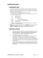
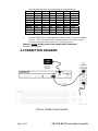
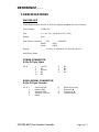
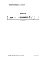
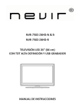
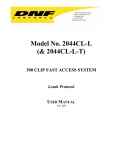
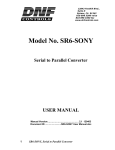
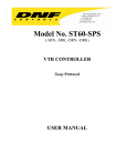
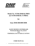
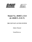
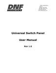
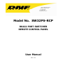
12843 Foothill Blvd. Suite C Sylmar, California 91342 V: 818.898.3380 F: 818.898.3360 [email protected] Model No. SW32PS-RCP RS422 PORT SWITCHER REMOTE CONTROL PANEL User Manual Rev 1.01 TABLE OF CONTENTS REVISION HISTORY 2 GETTING STARTED . . . 3 1. 2. 3. 4. 5. DESCRIPTION INSTALLATION CONNECTION DIAGRAM OPERATION a. MAKE A ROUTE b. VIEW THE ROUTES c. DISCONNECT ROUTE d. SAVE PRESET e. RESTORE PRESET f. SETUP GANG g. DISCONNECT GANG SELF-TEST PROCEDURE a. KEYBOARD TEST b. SYSTEM PORT TEST REFERENCE . . . 6. 7. 8. SPECIFICATIONS POWER CONNECTOR RS422 SERIAL CONNECTOR GPI CONNECTOR FRONT PANEL LAYOUT DNF CONTROLS LIMITED WARRANTY 3 3 4 5 5 5 5 5 5 6 6 7 7 7 9 9 9 9 10 11 13 Manual Version ...................................................... 1.01 090407 Document No: ........................... SW32PS-RCP_User_Manual.doc SW32PS-RCP Port Switcher Controller Page 1 of 13 1. REVISION HISTORY 080505 090407 Page 2 Of 13 1.0 1.01 Original document. Corrected ID Switch numbering. SW32PS-RCP Port Switcher Controller Getting Started . . . 2. DESCRIPTION The control panel consists of the ST100 controller hardware and the special software that allows controlling the SW32PS for the following functionality: Make route, view routes, gang outputs to input, disconnect route, disconnect gang, save preset, restore preset. Easy to read LCD Display has 2 lines by 20 characters. Shows source (From) and destination (To) routing and gang information. 6-function keypad provides: From (Select Source) To (Select Device) View (View active router) Take (Enable the selected route) Gang (User control of multiple destinations) Preset (Select Preset) Ideal for: Television Stations, Video Productions, Cable TV, Video Post Production, Duplication Houses NOTE: Words enclosed in brackets, such as [TAKE] indicate buttons on the SW32PS-RCP. Buttons shown with a “+” between them, for example [SHIFT] + [TAKE], indicate two keys pressed simultaneously. 3. INSTALLATION a. Plug one end of a 9-pin cable into the connector labeled “VTR” on the back of the controller. Plug the other end into one of the connectors on the port expander. Plug the port expander into the connector labeled “RS422” on the back of the SW32PS port switcher. b. Dip Switches Configuration for SW32PS-RCP. Every SW32PS-RCP has to have a unique ID from 1 to 10. The ID should match the External Device number set in the SW32PS. For example, if you use only one SW32PS-RCP with the SW32PS, the External Device should be set to 1 and the ID of the RCP should be 01. (The ID can be seen on the second line of the display during the power up of the RCP.) If you use two SW32PS-RCPs with the SW32PS, the External Device should be set to 2 and the ID of the RCPs should be 01 and 02. (The IDs can be seen on the second line of the display during the power up of the RCP.) SW32PS-RCP Port Switcher Controller Page 3 of 13 Use the table below to set the switches for SW6 SW5 SW4 SW3 ID: 01 Left Left Left Left ID: 02 Left Left Left Left ID: 03 Left Left Left Left ID: 04 Left Left Left Right ID: 05 Left Left Left Right ID: 06 Left Left Left Right ID: 07 Left Left Left Right ID: 08 Left Left Right Left ID: 09 Left Left Right Left ID: 010 Left Left Right Left c. the desired ID: SW2 SW1 Left Right Right Left Right Right Left Left Left Right Right Left Right Right Left Left Left Right Right Left Connect DB9F side of supplied power supply into the connector labeled “Power”. Then connect the IEC to Edison cable to the power supply. Connect the power cable to 90 VAC to 240 VAC source. Caution: Do Not Hot Plug the Power Supply DB9F connector! Installation is complete. 4. CONNECTION DIAGRAM TYPICAL CONNECTION DIAGRAM Page 4 Of 13 SW32PS-RCP Port Switcher Controller 5. OPERATION a. MAKE A ROUTE 1) Press [FROM]. The FROM indicator will turn on. The left side of the display shows the currently selected FROM connector (PORT1-32). 2) Turn the Wheel until the desired FROM point is displayed. 3) Press [TO]. The TO indicator will turn on. The right side of the display shows the currently selected TO connector (PORT1-32). Turn the Wheel until the desired TO point is displayed. 4) Press [TAKE] to route the FROM input to the TO output. NOTE: No Route is made until [TAKE] is pressed. NOTE: The Route that involves the selected FROM and/or TO will be disconnected prior to making the new route. b. c. d. VIEW THE ROUTES 1) Press [VIEW]. The VIEW indicator will turn on. 2) Turn the Wheel to scroll through all ports that are displayed on the first line of the display. DISCONNECT ROUTE 1) Press [FROM]. 2) Turn the Wheel until OFF is displayed. 3) Press [TO]. 4) Turn the Wheel to find the destination that you wish to turn off. 5) Press [TAKE] to turn off the route. SAVE PRESET 1) Press [SHIFT] + [PRESET]. The PRESET indicator will turn on. The first line of the display will show “Save Preset 1”. 2) Turn the Wheel to select preset number 1-8. 3) Press [TAKE] to save current configuration into the selected preset. OR Press [ESC] to exit without saving. e. RESTORE PRESET 1) Press [PRESET]. The PRESET indicator will turn on. 2) Turn the Wheel to select preset number 1-8. 3) Press [TAKE] to restore selected preset. The first line of the display will show “Restore Preset 1”. OR Press [ESC] to exit without restoring. SW32PS-RCP Port Switcher Controller Page 5 of 13 f. SETUP GANG 1) Press [FROM]. The FROM indicator turns on. The left side of the display shows the currently selected FROM connector (PORT1-32). 2) Turn the Wheel to select the source port. 3) Press [TO]. The TO indicator turns on. The right side of the display shows the currently selected TO connector (PORT1-32). 4) Press [GANG]. The GANG indicator turns on. 5) Turn the Wheel to select the destination port. 6) Press [TAKE] to route the selected input to the selected destination. The second line of the display will show “PORT(X) Added”. 7) Repeat steps 5-6 to add additional routes to GANG. 8) Press [ESC] when done. FROM, TO and GANG indicators turn OFF. NOTE: The GANG function will only work properly if the GANG is Enabled on the SW32PS. It is the responsibility of the user to set GANG to Enabled in the SW32PS Setup Menu. (See the SW32PS Port Switcher User Manual for the instructions on how to enable / disable gang.) g. DISCONNECT GANG 1) Press [VIEW]. 2) Turn the Wheel to find the GANG to be disconnected. 3) Press [GANG]. The display will prompt “Disconnect switches?” 4) Press [TAKE] to break all the routes that are part of gang. OR Press [ESC] to exit. Page 6 Of 13 SW32PS-RCP Port Switcher Controller 6. SELF-TEST PROCEDURE Press [TAKE] + [PRESET] + [SHIFT], in that order, to enter the test mode. Press [TAKE] + [PRESET] + [SHIFT] at anytime to exit self-test mode. a. KEYBOARD TEST Press keys to see the appropriate scan code on the display. Turn the Wheel to see Wheel count on the display change: (F0-00-10). b. SYSTEM PORT TEST Plug an RS422 looping plug into RS422 connector on the back of the SW32PS-RCP. The display should say: “port- OK”. Unplug the RS422 looping plug. SW32PS-RCP Port Switcher Controller Page 7 of 13 Page 8 Of 13 SW32PS-RCP Port Switcher Controller REFERENCE . . . 7. SPECIFICATIONS SW32PS-RCP Power Requirements 90 VAC to 265 VAC adapter supplied with IEC connector Power Supply +5VDC, 3A Size (L” x W” x H”) 19”X8.5”X1.75” (1RU) Weight 4 lbs. Rear Panel Connectors GPI RS422 Power Display (D9F) (D9M) (D26HDF) 2 Line x 20 Character LCD display, back-lit. Data Entry Wheel POWER CONNECTOR 9-Pin D-Type, Male Pin # 1 2 3 4 5 +5v DC NC Ground NC NC 6 7 8 9 NC NC NC NC 6 7 8 9 Receive Common Receive B Í Transmit A Î Frame Ground RS422 SERIAL CONNECTOR 9-Pin D-Type, Female Pin # 1 2 3 4 5 Frame Ground Receive A Í Transmit B Î Transmit Common Spare SW32PS-RCP Port Switcher Controller Page 9 of 13 GPI CONNECTOR 26HD-Pin D-Type, Female (DB26HDF) Pin # 1 2 3 4 5 6 7 8 9 10 11 12 13 14 15 16 17 18 19 20 21 22 23 24 25 26 Page 10 Of 13 Output #1, No Output #2, No Output #3, No Output #4, No Output #5, No Output #6, No Output #6, No Output #8, No Ground Input #1, No Input #2, No Input #3, No Input #3, No Input #4, No Input #5, No Input #6, No Input #7, No Ground + 5v + 5v No Connection No Connection No Connection No Connection No Connection Ground Function Function Function Function Function Function Function Function Function Function Function Function Function Function Function Function SW32PS-RCP Port Switcher Controller 8. FRONT PANEL LAYOUT Front Panel SW32PS-RCP Port Switcher Controller Page 11 of 13 Page 12 Of 13 SW32PS-RCP Port Switcher Controller 9. DNF CONTROLS LIMITED WARRANTY DNF Controls warrants its product to be free from defects in material and workmanship for a period of one (1) year from the date of sale to the original purchaser from DNF Controls. In order to enforce the rights under this warranty, the customer must first contact DNF’s Customer Support Department to afford the opportunity of identifying and fixing the problem without sending the unit in for repair. If DNF’s Customer Support Department cannot fix the problem, the customer will be issued a Returned Merchandise Authorization number (RMA). The customer will then ship the defective product prepaid to DNF Controls with the RMA number clearly indicated on the customer’s shipping document. The merchandise is to be shipped to: DNF Controls 12843 Foothill Blvd., Suite C Sylmar, CA 91342 USA Failure to obtain a proper RMA number prior to returning the product may result in the return not being accepted, or in a charge for the required repair. DNF Controls, at its option, will repair or replace the defective unit. DNF Controls will return the unit prepaid to the customer. The method of shipment is at the discretion of DNF Controls, principally UPS Ground for shipments within the United States of America. Shipments to international customers will be sent via air. Should a customer require the product to be returned in a more expeditious manner, the return shipment will be billed to their freight account. This warranty will be considered null and void if accident, misuse, abuse, improper line voltage, fire, water, lightning or other acts of God damaged the product. All repair parts are to be supplied by DNF Controls, either directly or through its authorized dealer network. Similarly, any repair work not performed by either DNF Controls or its authorized dealer may void the warranty. After the warranty period has expired, DNF Controls offers repair services at prices listed in the DNF Controls Price List. DNF Controls reserves the right to refuse repair of any unit outside the warranty period that is deemed non-repairable. DNF Controls shall not be liable for direct, indirect, incidental, consequential or other types of damage resulting from the use of the product. ### SW32PS-RCP Port Switcher Controller Page 13 of 13