1
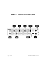
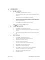
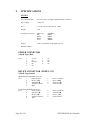
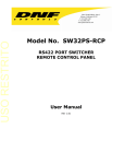
12843 Foothill Blvd. Suite C Sylmar, California 91342 V: 818.898.3380 F: 818.898.3360 [email protected] Model No. SW32PS RS422 PORT SWITCHER User Manual TABLE OF CONTENTS 1. REVISION HISTORY 3 GETTING STARTED . . . 4 2. 3. 4. 4 4 6 6 6 6 7 7 7 7 DESCRIPTION INSTALLATION OPERATION a. MAKE A ROUTE b. VIEW THE ROUTES c. SETUP GANG d. SAVE PRESET e. RESTORE PRESET f. DISCONNECT ROUTE g. DISCONNECT GANG ADVANCED FEATURES . . . 5. 6. 7. SOFTWARE OPTIONS a. GRASS VALLEY 7000 INTERFACE OPTION b. PESA INTERFACE OPTION c. SIGMA INTERFACE OPTION COMPUTER INTERFACE PROTOCOL COMMANDS SELF-TEST PROCEDURE a. KEYBOARD TEST b. SYSTEM PORT TEST c. FACTORY TEST ROUTES d. TEST IN/OUT PORTS e. TEST RS232 INTERFACE f. TEST RS422 INTERFACE Page 1 of 24 8 8 8 10 11 12 12 15 15 15 16 16 17 17 SW32PS RS422 Port Switcher REFERENCE . . . 8. 9. 10. 11. 18 SETUP MENU SPECIFICATIONS POWER CONNECTOR DEVICE (PORT 1-32) and RS422 SERIAL CONNECTOR RS232 SERIAL CONNECTOR GPI CONNECTOR FRONT/REAR PANEL LAYOUT DNF CONTROLS LIMITED WARRANTY 18 20 20 20 Error! Bookmark not defined. 21 21 22 23 Software Version: Basic Unit GV7000 Option PESA Option Sigma Option Manual Version..................................…..................... 3.7 030804 Document No:.....................................…...................SW32PS.doc Page 2 of 24 SW32PS RS422 Port Switcher 1. REVISION HISTORY 120902 Rev. 3.0 Revised Sec. 6, Computer Interface Protocol. 050503 Rev. 3.1 Revised Sec. 5, Software Options, para. a.10). 072503 Rev. 3.2 Added Learn Preset, Restore Preset Commands to Section 6 Commands. 091903 Rev. 3.3 Sect. 5.a.3): Corrected GV700 to GV7000. 101403 Rev. 3.4 Added RS422 Test to SELF-TEST PROCEDURE, Section 7. 102203 Rev. 3.5 Added Protect Setup and Unused Levels Setup for GV7000 Interface option. (Sect. 5.a.) 010704 Rev. 3.6 Company header information revised. Added DNF Controls Limited Warranty. 030804 Rev. 3.7 SPECIFICATIONS, Section 9: Changed weight from 4 lbs to 9 lbs. Page 3 of 24 SW32PS RS422 Port Switcher Getting Started . . . 2. DESCRIPTION The SW32PS is a low cost 32-port switcher for RS422 routing. 3. Route VTR to VTR / Route Controller to VTR. Automatically configures Ports. Easy to read LCD Display has 4 lines by 20 characters. Shows source (From) and destination (To) routing. 6-function keypad provides: From (Select Source) To (Select Device) View From (View by Sources) Take (Enable the selected route) Gang (User control of multiple destinations) Menu (User configuration Menu) Ideal for: Television Stations, Video Productions, Cable TV, Video Post Production, Duplication Houses Versions Available SW32PS-32 SW32PS-24 SW32PS-16 SW32PS-8 32 ports 24 ports 16 ports 8 ports INSTALLATION a. Plug one end of a 9-conductor, RS422 serial cable to a controller. Plug the other end of the cable into any of the 32-port connectors on the back of the switcher. b. Plug one end of a 9-pin cable into a VTR/DDR/Video Server. Plug the other end into any of the 32 connectors on the back of the switcher. c. Connect DB9F side of supplied power supply into the connector labeled “Power.” Then connect the IEC to Edison cable to the power supply. Connect the power cable to 90 VAC to 240 VAC source. Caution: Do Not Hot Plug the Power Supply (DB9F) ! Installation is complete. NOTE: Words enclosed in brackets, such as [TAKE] indicate buttons on the SW32PS. Buttons shown with a “+” between them, for example [SHIFT] + [TAKE], indicate two keys pressed simultaneously. Page 4 of 24 SW32PS RS422 Port Switcher TYPICAL CONNECTION DIAGRAM Page 5 of 24 SW32PS RS422 Port Switcher 4. OPERATION a. MAKE A ROUTE 1) Press [FROM]. The FROM indicator will turn on. The first line of the display shows you the currently selected FROM connector (PORT1-32). Turn the Wheel until the desired FROM point is displayed. 2) Press [TO]. The TO indicator will turn on. Second line of the display shows you the currently selected TO connector (PORT1-32). Turn the Wheel until the desired TO point is displayed. 3) Press [TAKE] to route the FROM input to the TO output. NOTE: No Route is made until [TAKE] is pressed. b. c. Page 6 of 24 VIEW THE ROUTES 1) Press [VIEW]. The VIEW indicator will turn on. 2) Turn the Wheel to scroll through all ports that are displayed on the first line of the display. 3) The second line of the display will show the port(s) connected to the selected port. SETUP GANG 1) Press [FROM]. The FROM indicator turns on. The first line of the display shows the selected input port. 2) Turn the Wheel to select the source port. 3) Press [TO]. The TO indicator turns on. The first line of the display shows the selected output port. 4) Press [GANG]. The GANG indicator turns on. 5) Turn the Wheel to select the destination port. 6) Press [TAKE] to route the selected input to the selected destination. The third line of the display will show “PORT(X) Added.” 7) Repeat steps 5-6 to add as many routes to GANG. 8) Press [ESC] when done. SW32PS RS422 Port Switcher d. SAVE PRESET 1) Press [SHIFT] + [PRESET]. The PRESET indicator will turn on. The first line of the display will show “Save Preset 1.” 2) Turn the Wheel to select preset number 1-8. 3) Press [TAKE] to save current configuration into the selected preset. OR Press [ESC] to exit without saving. e. RESTORE PRESET 1) Press [PRESET]. The PRESET indicator will turn on. The first line of the display will show “Restore Preset 1.” 2) Turn the Wheel to select preset number 1-8. 3) Press [TAKE] to restore selected preset. OR Press [ESC] to exit without restoring. f. g. DISCONNECT ROUTE 1) Press [FROM]. 2) Turn the Wheel until OFF is displayed. 3) Press [TO]. 4) Find the destination that is to be turned off. 5) Press [TAKE] to turn off the route. DISCONNECT GANG 1) Press [VIEW]. 2) Turn the Wheel to find the GANG to be disconnected. 3) Press [GANG]. The display will prompt “Disconnect switches?” 4) Press [TAKE] to break all the routes that are part of gang. OR Press [ESC] to exit. Page 7 of 24 SW32PS RS422 Port Switcher Advanced Features . . . 5. SOFTWARE OPTIONS a. GRASS VALLEY 7000 INTERFACE OPTION 1) GV7000 SERIM PORT 2) GV7000 SERIM PORT Page 8 of 24 If the GV7000 20-TEN SERIM has an RS422 port, connect one end of the 9-pin cable to the SERIM port, connect the other end of the cable to the RS422 port on the back of the SW32PS using turnaround adapter (provided). TURNAROUND ADAPTER 1 2 3 4 5 6 7 8 9 NC 7 8 NC NC NC 2 3 9 SW32PS RS422 PORT If the GV7000 20-TEN SERIM has an RS232 port, connect one end of RS232 NULL-MODEM cable to the SERIM port, connect the other end of the cable to the RS232 port on the back of the SW32PS. NULL-MODEM CABLE 1 2 3 4 5 6 7 8 9 NC 3 2 NC 5 NC NC NC NC SW32PS RS232 PORT SW32PS RS422 Port Switcher 3) Configure AMEZI card on the GV7000 for 20-TEN protocol. 4) Press [MENU]. 5) Turn the Wheel until the display says: “Ext. Interface:” 6) Press [TAKE] to select RS232 or RS422, depending on what interface you are using. 7) Turn the Wheel until the display says “Parity: ” 8) Press [TAKE] to select ODD, EVEN or NONE to match parity on what the AMEZI card is configured for. 9) Turn the Wheel until the display says “BAUD RATE:” 10) Press [TAKE] to select 9600, 19.2K or 38.4K to match baud rate on what the AMEZI card is configured for. 11) Turn the wheel until the display says “Protect.” 12) Press [TAKE] to enable or disable Protecting Destinations. 13) Turn the wheel until the display says “UNUSED LVLS:” 14) Press [TAKE] to select sending the status of unused levels as “NOTConnected” or “DISABLED.” 15) Turn the Wheel until the display says “Set STROBE.” 16) Press [TAKE]. 17) The display shows current strobe (level) number. 18) Turn the Wheel to select level 1-4. 19) Press [ESC] twice to exit SETUP MENU. Setup is complete. The GV7000 can now control the SW32PS. NOTE: Default settings for communications are: RS422, 34.8, No parity, 8 bits data, 1 stop bit. Page 9 of 24 SW32PS RS422 Port Switcher b. PESA INTERFACE OPTION The SW32PS with the Pesa Interface Option makes the SW32PS act as a matrix of a Pesa switcher, which allows control of switching of RS422 signals. 1) INSTALLATION Connect the connector labeled “RS422” on the back of the SW32PS using a 9pin cable and a supplied turnaround adapter to the COM3/PRC connector on the back of the PESA SYSTEM CONTROLLER. (Communication Protocol: 38.4 K, No Parity, 8 bits, 1 stop bit) 2) 3) SETUP ON THE WIN 3500 CONTROL SYSTEM a) Using PESA WIN 3500 software to create an RS422 component, name it, then assign a level to it. b) Component type must be PRC. c) Assign a strobe number (1- 62). Input and Output Offsets should be set to 0. SETUP on the SW32PS a) Press [MENU] on the SW32PS. b) The display shows “Set Strobe.” Press [TAKE]. c) The display shows current Strobe number. d) Turn the Wheel to select a strobe number 1-62. The number must match a strobe number that was assigned to the component on the WIN 3500 software. e) Press [ESC] twice to leave the Strobe Setup mode. The SW32PS now behaves as a matrix of a PESA switcher. NOTE: In the MENU, FROM, TO and VIEW modes, the SW32PS stops communication with the PESA router. If no key is pressed or no Wheel movement detected for 10 seconds in any mode, the SW32PS automatically returns to normal operation mode and communication with the PESA Router is restored. Page 10 of 24 SW32PS RS422 Port Switcher c. SIGMA INTERFACE OPTION 1) Connect one end of a 9-pin custom cable (see wiring information below) to any one of “CONTROL BUS” connectors on the back of the 2126 SLV cards of the SIGMA control panel. Connect the other end of this 9-pin cable to the GPI connector on the back of SW32PS. 2) Press [MENU] on the SW32PS. 3) The display shows “SET LEVEL.” 4) Press [TAKE]. 5) The display shows current level number. 6) Turn the Wheel to assign level number 1-4. 7) Press [ESC] twice to leave the MENU mode. Setup is complete. The SW32PS now behaves as a level on the SIGMA router. Interface Cable DB9 Male (Sigma Equipment) DB9Male (DNF Equipment) Pin 1 ÎÎÎÎÎÎÎÎÎÎÎ Pin 9 Pin 2 ÎÎÎÎÎÎÎÎÎÎÎ Pin 2 Pin 3 ÎÎÎÎÎÎÎÎÎÎÎ Pin 3 Pin 4 ÎÎÎÎÎÎÎÎÎÎÎ Pin 4 Pin 5 ÎÎÎÎÎÎÎÎÎÎÎ Pin 5 Pin 6 ÎÎÎÎÎÎÎÎÎÎÎ Pin 6 Pin 7 ÎÎÎÎÎÎÎÎÎÎÎ Pin 7 Pin 8 ÎÎÎÎÎÎÎÎÎÎÎ Pin 8 Pin 9 ÎÎÎÎÎÎÎÎÎÎÎ Pin 1 NOTE: There is no GPI control available if the Sigma Interface Option is installed. Page 11 of 24 SW32PS RS422 Port Switcher 6. COMPUTER INTERFACE PROTOCOL Connection: Connect RS232 COM PORT on computer to the “RS232” labeled port on the rear of the SW32PS. See RS232 SERIAL CONNECTOR pin out diagram below. Communication Format: BAUD: 38400 PARITY: None DATA: 8 Bits START: 1 Bit STOP: 1 Bit COMMANDS For the command descriptions and examples below: All characters enclosed in single quotes represent ASCII Characters. For example, ‘R’ represents the hexadecimal value 0x52. The “+” symbol should not be included in the command string. This symbol is used for the sole purpose of enhancing readability. For example, the command string ‘1’ + ‘2’ + ‘3’ should be transmitted as 0x31 0x32 0x33. The CR symbol represents Carriage Return, which has a hexadecimal value of 0x0D. Replace the CR symbol with its hexadecimal value of 0x0D. a) Route: Set From To Route Route the “FROM” port to the “TO” port Command = ‘R’+ FROM + TO + CR FROM = Source Port, TO = Destination Port Response = ‘O’ + ‘K’ + CR Example # 1: FROM Port 4 TO Port 23 Command = ‘R’ + ‘0’ + ‘4’ + ‘2’ + ‘3’ + CR Response = ‘O’ + ‘K’ + CR Example # 2: FROM Port 13 TO Port 5. Command = ‘R’ + ‘1’ + ‘3’ + ‘0’ + ‘5’ + CR Response = ‘O’ + ‘K’ + CR Page 12 of 24 SW32PS RS422 Port Switcher b) Status: Get Status of Selected Port Returns the status of the passed port. Command = ‘S’ + PORT + CR PORT = the 2-digit ASCII representation of the port number. Response = ‘S’ + FROM + TO + CR Example #1: Get status of port 13 using route in previous example. Command = ‘S’ + ‘1’ + ‘3’ + CR Response = ‘S’ + ‘1’ + ‘3’ + ‘0’ + ‘5’ + CR Example #2: Get status of port 5 using route in previous example. Command = ‘S’ + ‘0’ + ‘5’ + CR Response = ‘S’ + ‘1’ + ‘3’ + ‘0’ + ‘5’ + CR c) Status: Request Status of All Crosspoints Returns the Source Number routed to each Destination. Command = ‘X’ + CR Response = ‘X’ + CROSSPOINTS RETURNED + CROSSPOINT DATA CROSSPOINTS RETURN = Total number of crosspoints included in response represented as a 2-digit ASCII number. CROSSPOINT DATA = Source number for each destination, represented as a 2digit ASCII number. Source numbers are returned in order starting from Destination 1. Example: SW32-8 with following routes: 5 to 1, 2 to 6, 2 to 7, 3 to 4 Command = ‘X’ + CR Response = X+08(total of 8 crosspoints) +05 +00 +00 +03 +00 +02 +02 +00 + CR d) Preset: Learn Preset Save the current configuration of the SW32PS into one of the available presets. There are 8 presets available, numbered 1 – 8. Command: ‘L’ + Preset # + CR Where Preset # = ‘1’ through ‘8’ Response: ‘O’ + ‘K’ + CR Example #1: Learn Preset #1 Command = ‘L + ‘1’ + CR Response = ‘O’ + ‘K’ + CR Example #2: Learn Preset #3 Command = ‘L’ + ‘3’ + CR Response = ‘O’ + ‘K’ + CR Page 13 of 24 SW32PS RS422 Port Switcher e) Preset: Restore Preset Copy selected Preset into the current SW32PS configuration. There are 8 presets on the SW32PS numbered 1 – 8. Command: ‘P’ + Preset # + CR Where Preset # = ‘1’ through ‘8’ Response: ‘O’ + ‘K’ + CR Example #1: Restore Preset #1 Command = ‘P’ + ‘1’ + CR Response = ‘O’ + ‘K’ + CR Example #2: Restore Preset #3 Command = ‘P’ + ‘3’ + CR Response = ‘O’ + ‘K’ + CR Page 14 of 24 SW32PS RS422 Port Switcher 7. SELF-TEST PROCEDURE Press [SHIFT] + [BLANK] (blank key) to enter the test mode. Turn the Wheel to move between self-test tasks. Press [TAKE] to select a task. Tasks include: KEYBOARD TEST SYSTEM PORT TEST FACTORY TEST I/O PORT TEST RS232 TEST RS422 TEST Press [ESC] at anytime to exit self-test mode. a. KEYBOARD TEST Press keys to see the appropriate LED turn on and appropriate scan code on the display. Turn the Wheel to see Wheel count on the display change. Press [SHIFT] + [BLANK] (blank key) to exit self-test mode. The unit will reset upon exit. b. SYSTEM PORT TEST 1) Plug an RS422 looping plug into RS422 connector on the back of the SW32PS. The display should say: “RS422 port- OK.” The third line of the display should say “422 Transmitter ON.” The fourth line of the display should prompt “Take- Tx Off, ESC- EXIT.” 2) Press [TAKE] to turn the transmitter off. The first line of the display should say: “422 transmitter OFF,” The second line of the display should say “No communication.” Page 15 of 24 3) Unplug the RS422 looping plug. 4) Plug a RS232 looping plug into the RS232 connector on the back of the unit. If the communication is normal, the first line of the display will say: “RS232 port- OK” 5) Press [ESC] to exit system port setup. The unit will reset upon exit. SW32PS RS422 Port Switcher c. d. FACTORY TEST ROUTES 1) Plug one end of the standard 9-pin cable into RS422 connector on the back of the SW32PS. 2) Plug the other end into PORT1 connector on the back of the SW32PS. 3) Plug the RS422 looping plug into PORT2 connector on the back of the SW32PS. 4) The third line of the display should say “From Odd To Even.” The first line of the display should say: “Route= OK.” 5) Continue by moving the RS422 cable and Loopthru to the next position (422PORT3, Loopthru- PORT4, then 422-PORT5, Loopthru- PORT6, and so on). 6) Press [TAKE] to swap FROMs and TOs. Now RS422 cable needs to go into even-numbered ports, and Loopthru needs to plug into odd-numbered ports, e.g.: 422cable- PORT2, Loopthru- PORT1; 422cable- PORT4, loopthru- PORT3 etc). 7) Press [ESC] to exit the test. TEST IN/OUT PORTS 1) Connect one end of the standard 9-pin cable to the RS422 connector on the back of the SW32PS. 2) Connect the other end of the 9-pin cable to the PORT1 connector on the back of the SW32PS. 3) The display prompts: TEST: PORT1. 4) Press [TAKE] to select port to test. The second line of the display shows “PORT1= OK” if the port works right. OR PORT1= NOT OK” if the port doesn’t work. Page 16 of 24 5) Disconnect one end of the 9-pin cable from the PORT1. 6) Plug it into another port. 7) Turn the Wheel until the first line of the display shows the port number you have the 9-pin cable connected to. 8) Press [TAKE] to test that port number. 9) Repeat steps 2-6 to test all the ports. 10) Press [ESC] to exit the test mode. SW32PS RS422 Port Switcher e. TEST RS232 INTERFACE NOTE: Only accessible if External Interface is set to RS232. f. 1) Connect one end of the standard 9-pin cable to the external control source (your PC). 2) Connect the other end to the RS232 port on the back of the SW32PS. 3) The first line of the display shows: “RS232 Interface Data” 4) Send some data from the PC. 5) The second line of the display should show sent data. 6) Press [ESC] to exit the test mode. TEST RS422 INTERFACE NOTE: Only accessible if External Interface is set to RS422. Page 17 of 24 1) Connect one end of the standard 9-pin cable to the external control source. 2) Connect the other end to the RS422 port on the back of the SW32PS. 3) The first line of the display shows: “RS422 Interface Data” 4) Send some data from the external control source. 5) The second line of the display should show sent data. 7) Press [ESC] to exit the test mode. SW32PS RS422 Port Switcher Reference . . . 8. SETUP MENU a. Press [MENU] to enter MENU mode. Scroll the Wheel to move between MENU options. b. Press [TAKE] to change mode of the device. c. Press [ESC] at anytime to exit MENU mode. MENU MODES (Turning Wheel Clockwise) SET STROBE Grass Valley Group and PESA Software Options Only LOCAL MODE SETUP LOCAL mode DISABLE - disable TAKE and CLEAR operations from the front panel. You will still be able to view routes. LOCAL mode ENABLE - enable TAKE and CLEAR operations from the front panel. GANG MODE SETUP GANG MODE DISABLE- Disables GANG mode. In that mode, every new route breaks a previous route that includes the same FROM. For example: FROM: PORT 1 was routed TO: PORT2. Created new route: FROM: PORT 1 is now routed TO: PORT3. The previous route is broken. PORT2 is not routed to anything. GANG MODE ENABLE- Enables GANG mode. In that mode, every new route that includes the same FROM does not break a previous one. For example: FROM: PORT 1 was routed TO: PORT2. Created new route: FROM: PORT 1 is now routed TO: PORT3. The previous route is not broken. PORT1 now controls both PORT2 and PORT3. CONTROLLER/ DEVICE MODE SETUP FROM CONTROLLER TO DEVICE In that mode, FROM port is a port to which a controller is connected. TO port is a port to which a controlled device is connected. TO CONTROLLER FROM DEVICE In that mode, TO port is a port to which a controller is connected. FROM port is a port to which a controlled device is connected. CLEAR ALL ROUTES The display will prompt “Are You Sure?” Press [TAKE] to clear or [ESC] or Turn the Wheel to EXIT. This option will clear the current configuration of the switcher, BUT WILL NOT CLEAR PRESETS. CLEAR ALL MEMORY The display will prompt “Are You Sure?” Press [TAKE] to clear or [ESC] or Turn the Wheel to EXIT. This option will clear the current configuration of the switcher AND PRESETS. Page 18 of 24 SW32PS RS422 Port Switcher SET FACTORY DEFAULTS Sets Default parameters: LOCAL MODE - ENABLED. GANG MODE - ENABLED. FROM CONTROLLER TO DEVICE. DISPLAY VERSION NUMBER Display Version and date code of software. EXTERNAL DEVICE SETUP Turn the Wheel to select number of external devices. The display shows: “# of External Dev = xx”, the third and fourth lines of the display show: “Sel. 0 for RS232 port or 1-10 for 422 port.” If the user selects 0, RS232 port is active and the Port Switcher constantly listens to the commands coming from the PC. If the user selects 1 through 10, the Port Switcher will query every device every frame. Page 19 of 24 SW32PS RS422 Port Switcher 9. SPECIFICATIONS SW32PS Power Requirements 90 VAC to 265 VAC adapter supplied with IEC connector Power Supply +5VDC, 3A Size (L” x W” x H”) 19”X8.5”X5.25” (2RU) Weight 9 lbs. Rear Panel Connectors PORT1-32 GPI RS422 RS232 Power Display 4 Line x 20 Character LCD display, back-lit. (All DB9F) (DB9F) (DB9F) (DB9F) (DB9M) Data Entry Wheel POWER CONNECTOR 9-Pin D-Type, Male Pin # 1 2 3 4 5 +5v DC NC Ground NC NC 6 7 8 9 NC NC NC NC DEVICE CONNECTOR (PORTS 1-32) 9-Pin D-Type, Female FROM DEVICE (depending on set-up) Pin # 1 Frame Ground 2 Receive A Í 3 Transmit B Î 4 Transmit Common 5 Spare 6 7 8 9 Receive Common Receive B Í Transmit A Î Frame Ground TO DEVICE (depending on set-up) Pin # 1 Frame Ground 2 Transmit A Î 3 Receive B Í 4 Transmit Common 5 Spare 6 7 8 9 Receive Common Transmit B Î Receive A Í Frame Ground Page 20 of 24 SW32PS RS422 Port Switcher RS422 SERIAL CONNECTOR 9-Pin D-Type, Female Pin # 1 2 3 4 5 Frame Ground Receive A Í Transmit B Î Transmit Common Spare 6 7 8 9 Receive Common Receive B Í Transmit A Î Frame Ground 6 7 8 9 NC NC NC NC RS232 SERIAL CONNECTOR 9-Pin D-Type, Female Pin # 1 2 3 4 5 NC Transmit Receive NC Ground GPI CONNECTOR 9-Pin D-Type, Female Pin # Page 21 of 24 1 2 3 4 5 Input # 1, Select Preset # Input # 2, Select Preset # Input # 3, Select Preset # Input # 4, Select Preset # Input # 5, Select Preset # 1 2 3 4 5 6 7 8 9 Input # 6, Select Preset # 6 Input # 7, Select Preset # 7 Input # 8, Select Preset # 8 Ground SW32PS RS422 Port Switcher 10. FRONT/REAR PANEL LAYOUT Front Panel Rear Panel Page 22 of 24 SW32PS RS422 Port Switcher 11. DNF CONTROLS LIMITED WARRANTY DNF Controls warrants its product to be free from defects in material and workmanship for a period of one (1) year from the date of sale to the original purchaser from DNF Controls. In order to enforce the rights under this warranty, the customer must first contact DNF’s Customer Support Department to afford the opportunity of identifying and fixing the problem without sending the unit in for repair. If DNF’s Customer Support Department cannot fix the problem, the customer will be issued a Returned Merchandise Authorization number (RMA). The customer will then ship the defective product prepaid to DNF Controls with the RMA number clearly indicated on the customer’s shipping document. The merchandise is to be shipped to: DNF Controls 12843 Foothill Blvd., Suite C Sylmar, CA 91342 USA Failure to obtain a proper RMA number prior to returning the product may result in the return not being accepted, or in a charge for the required repair. DNF Controls, at its option, will repair or replace the defective unit. DNF Controls will return the unit prepaid to the customer. The method of shipment is at the discretion of DNF Controls, principally UPS Ground for shipments within the United States of America. Shipments to international customers will be sent via air. Should a customer require the product to be returned in a more expeditious manner, the return shipment will be billed to their freight account. This warranty will be considered null and void if accident, misuse, abuse, improper line voltage, fire, water, lightning or other acts of God damaged the product. All repair parts are to be supplied by DNF Controls, either directly or through its authorized dealer network. Similarly, any repair work not performed by either DNF Controls or its authorized dealer may void the warranty. After the warranty period has expired, DNF Controls offers repair services at prices listed in the DNF Controls Price List. DNF Controls reserves the right to refuse repair of any unit outside the warranty period that is deemed non-repairable. DNF Controls shall not be liable for direct, indirect, incidental, consequential or other types of damage resulting from the use of the product. ### Page 23 of 24 SW32PS RS422 Port Switcher