1
User’s Manual
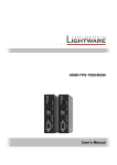
MX-RCP16
MX-RCP32
Page 2 / 32
Section 1. Introduction
MX-RCP32
User’s Manual Rev. 0.8
Table of contents
1.
INTRODUCTION .............................................................................................................................. 5
1.1. DESCRIPTION.................................................................................................................................5
1.2. FRONT PANEL VIEW ........................................................................................................................6
1.3. REAR VIEW ....................................................................................................................................6
2.
INSTALLATION ............................................................................................................................... 7
2.1. MATRIX ROUTER CONTROL SYSTEM.................................................................................................7
2.1.1. Building the system ..............................................................................................................7
2.1.2. Configuring the system ........................................................................................................7
2.2. UNIVERSAL DEVICE CONTROL SYSTEM.............................................................................................8
2.2.1. Building the system ..............................................................................................................8
2.2.2. Configuring the system ........................................................................................................8
3.
CONFIGURATION ........................................................................................................................... 9
3.1. SETTINGS ON THE UNIT...................................................................................................................9
3.1.1. Setting the communication protocol .....................................................................................9
3.1.2. Resetting the IP address .....................................................................................................9
3.2. SETTINGS WITH LIGHTWARE MATRIX CONTROLLER SOFTWARE...................................................... 10
4.
OPERATION .................................................................................................................................. 10
4.1. OPERATIONAL MODES OVERVIEW ................................................................................................. 10
4.1.1. Matrix control protocols ..................................................................................................... 10
4.1.2. Universal device control protocol ...................................................................................... 11
4.2. FRONT PANEL OPERATIONS IN X-Y MODE ..................................................................................... 11
4.2.1. CONTROL LOCK.............................................................................................................. 11
4.2.2. TAKE / AUTOTAKE modes .............................................................................................. 11
4.2.3. Viewing crosspoint state ................................................................................................... 12
4.2.4. Switching in X-Y mode ...................................................................................................... 13
4.2.5. OUTPUT LOCK ................................................................................................................ 13
4.2.6. Switching operations flowchart in X-Y mode .................................................................... 15
4.2.7. Preset operations .............................................................................................................. 16
4.3. FRONT PANEL OPERATIONS IN Y MODE ......................................................................................... 17
4.3.1. CONTROL LOCK.............................................................................................................. 17
4.3.2. Switching in Y mode ......................................................................................................... 17
4.3.3. Switching operations flowchart in Y mode ........................................................................ 18
4.4. FRONT PANEL OPERATIONS IN SALVO MODE ............................................................................... 18
4.4.1. CONTROL LOCK.............................................................................................................. 18
4.4.2. Executing salvos ............................................................................................................... 19
4.4.3. Verified salvo operations flowchart ................................................................................... 19
4.5. OPERATION IN UDC MODE .......................................................................................................... 20
5.
USING LIGHTWARE MATRIX CONTROLLER ............................................................................ 20
5.1. INSTALLING THE MATRIX CONTROLLER SOFTWARE ....................................................................... 20
5.2. ESTABLISHING THE CONNECTION ................................................................................................. 21
5.3. CONTROL MENU .......................................................................................................................... 23
5.3.1. Controlled target ............................................................................................................... 23
5.3.2. Salvo commands .............................................................................................................. 23
5.4. STATUS MENU............................................................................................................................. 24
5.4.1. IP settings ......................................................................................................................... 24
6.
PROGRAMMER’S REFERENCE .................................................................................................. 26
6.1. MATRIX CONTROL PROTOCOLS .................................................................................................... 26
6.2. UDC PROTOCOL ......................................................................................................................... 26
6.2.1. Sent responses ................................................................................................................. 26
6.2.2. Accepted commands ........................................................................................................ 26
Section 1. Introduction
Page 3 / 32
7.
SPECIFICATIONS ......................................................................................................................... 27
7.1. MECHANICAL DRAWINGS (MX-RCP16) ........................................................................................ 28
7.2. MECHANICAL DRAWINGS (MX-RCP32) ........................................................................................ 29
8.
VERSION APPLICABILITY........................................................................................................... 30
9.
WARRANTY .................................................................................................................................. 30
10. QUALITY CHECK RECORD ......................................................................................................... 31
11. DOCUMENT REVISION HISTORY ............................................................................................... 32
Page 4 / 32
Section 1. Introduction
MX-RCP32
User’s Manual Rev. 0.8
1. Introduction
1.1. Description
Lightware MX-RCP16 and MX-RCP32 are remote control panels for controlling
Lightware matrix routers. Additionally the control panels support group commands
(salvo) or can be used as universal device control with a simple protocol.
The control panels have illuminated and easily relegendable front panel buttons
and an Ethernet LAN port for connecting to the controlled device.
Section 1. Introduction
Page 5 / 32
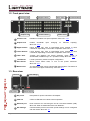
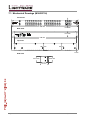
1.2. Front panel view
1 Control Lock
3 Upper buttons
2 Output Lock
4 Lower buttons
Take / Auto 5
6 Preset buttons
Mode select 7
1 Control Lock
Disables or enables front panel operation. More info: 4.2.1.
2 Output Lock
Inhibits accidental
More info: 4.2.5.
3 Upper buttons
Upper buttons may refer to input/output ports, presets or salvo
commands, depending on the mode of operation. More info: 4.1.
4 Lower buttons
Lower buttons may refer to input/output ports, presets or salvo
commands, depending on the mode of operation. More info: 4.1.
5 Take / Auto
Toggles and displays the actual switching mode (TAKE or
AUTOTAKE; available only in X-Y operation mode). More info: 4.2.2.
6
7
input
changing
on
selected
output(s).
Load Preset
Loads a previously saved crosspoint configuration.
Save Preset
Stores actual matrix state, in one of the preset memories.
More info: 4.2.7.
Mode select
The operation mode can be selected with these buttons. The button of
the active mode lights continuously. More info: 4.1.
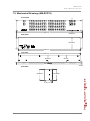
1.3. Rear view
CPU live 2
DC power 1
4 DIP settings
3 Ethernet port
1 DC power
Receptacle for power external 5V DC adaptor.
2 CPU live
CPU live LED blinks to indicate normal operation.
3 Ethernet port
RJ45 connector for connecting the unit to Local Area Network (LAN).
More info: Hiba! A hivatkozási forrás nem található..
4 DIP settings
Communication protocol and other special settings can be configured
with this switch. More info: 3.1.
Page 6 / 32
Section 1. Introduction
MX-RCP32
User’s Manual Rev. 0.8
2. Installation
The RCPs can be used to remote control matrix routers, or as a simple button
array to control any device through a simple protocol. The below guide describes
how to build and configure these systems.
2.1. Matrix router control system
2.1.1. Building the system
Step 1. Install a Lightware matrix router with sources and displays as needed.
Step 2. Connect the matrix to a network hub, switch or router with its Ethernet port.
Step 3. Connect the RCP to the same network as the matrix.
a) One RCP unit can connect to one matrix router
b) More RCP units can connect to the same matrix router depending
on the router’s Webserver firmware version.
Step 4. Set the RCP unit’s protocol to 0, 1, 2, 4 or 5 with the DIP switch.
Step 5. Power up the devices.
2.1.2. Configuring the system
Step 1. Check that the RCP unit protocol is set to 0, 1, 2, 4 or 5.
Step 2. Set the controlled matrix to fix IP configuration, and set the IP address
manually. Remember the IP address and the port number.
a) This can be done through the front panel LCD on the matrix or with
the Matrix Controller software remotely.
Step 3. Connect to the RCP with the Matrix Controller software.
a) The RCP has a fix IP address as factory default: 192.168.254.254.
To change this, use a crosslink UTP cable and connect the unit
directly to your computer’s Ethernet port. Or enable DHCP through
the front panel buttons. More info: 3.1.2.
b) The three operation mode buttons will blink green until the RCP
unit is in configuration mode.
Step 4. Set the IP address and port of the matrix as the target IP address and port.
Step 5. Close the Matrix Controller software to disconnect from the RCP.
Step 6. The RCP automatically tries to connect to the matrix on the set IP address.
If the connection could not be established, the “OUTPUT LOCK” button
blinks continuously.
Step 7. The system is ready to use. The RCP will function just as it would be the
front panel control of the connected matrix router.
Section 2. Installation
Page 7 / 32
2.2. Universal device control system
The RCP can operate as a universal device controller (UDC). In this mode the RCP
sends a command regarding each button press or release. These commands can
be processed by a third party device. On the other hand, the RCP can take
commands to control its built-in LEDs.
2.2.1. Building the system
Step 1. Prepare a device that implements the UDC protocol (UDC server).
Step 2. Connect the UDC server to a network hub, switch or router.
Step 3. Connect one or more RCP units to the same network. (One RCP can
connect to one UDC server at a time, but several RCPs could connect to
the UDC server depending on its configuration.)
Step 4. Set the RCP unit’s protocol to 3 with the DIP switch.
Step 5. Power up the devices.
2.2.2. Configuring the system
Step 1. Check that the RCP unit protocol is set to 3.
Step 2. Set the UDC server to a fix IP address and port number.
Step 3. Connect to the RCP with the Matrix Controller software.
a) The RCP has a fix IP address as factory default: 192.168.254.254.
To change this, use a crosslink UTP cable and connect the unit
directly to your computer’s Ethernet port. Or enable DHCP through
the front panel buttons. More info: 3.1.2.
b) The three operation mode buttons will blink green until the RCP
unit is in configuration mode.
Step 4. Set the IP address and port number of the UDC server as the target IP
address and port number.
Step 5. Close the Matrix Controller software to disconnect from the RCP.
Step 6. The RCP automatically tries to connect to the UDC server on the set IP
address. (There is no automatic indication to show whether the connection
is established or not. The server should detect the connection and send
some commands for the RCP unit to generate indication.)
Step 7. The system is ready to use. The RCP will send a command if a button is
pressed down or released. The LEDs can be switched ON/OFF/BLINK by
sending command to the RCP.
Page 8 / 32
Section 2. Installation
MX-RCP32
User’s Manual Rev. 0.8
3. Configuration
3.1. Settings on the unit
3.1.1. Setting the communication protocol
Changing
The communication protocol can be changed on the rear of the unit:
Step 1. Set the DIP switch as a binary representation of the protocol number.
0
Lightware
1
Lightware
2
Secondary
3
UDC
12345678
12345678
12345678
12345678
4
5
Lightware Secondary
(free salvo) (free salvo)
12345678
12345678
Step 2. Check the protocol on the front panel as described above.
Viewing
The communication protocol can be checked on the front panel (except UDC):
Step 1. Press and hold the Control Lock button for 4 seconds. (Control Lock button
lights in up red continuously).
Step 2. Press and keep pressed the Output Lock button. The current protocol
indication will light up.
3.1.2. Resetting the IP address
The unit’s Ethernet port can be set to factory default IP configuration or to DHCP
mode with front panel buttons. To set the IP configuration perform the following:
Step 1. Ensure that there is no active connection on the Ethernet port. You have to
unplug the LAN cable.
Step 2. Press and hold the Control Lock button for 4 seconds. (Control Lock button
lights in up red continuously).
Step 3. Press and keep pressed the Output Lock button (the current protocol
indication will light up).
Step 4. Press and release the
a) Load Preset button to set the factory default IP settings
IP address:
port number:
subnet mask:
gateway:
192.168.254.254
10001
255.255.0.0
0.0.0.0
b) Save Preset button to set DHCP enabled
IP address:
port number:
subnet mask:
gateway:
Acquired with DHCP
unchanged
unchanged
unchanged
Step 5. A light sequence will occur to confirm the command. (Save Preset, Load
Preset and Take/Auto buttons will light up one after the other.)
Step 6. Reinsert the LAN cable to the Ethernet port.
Step 7. The RCP unit will restart, and try to connect to the set target IP address.
Section 3. Configuration
Page 9 / 32
3.2. Settings with Lightware Matrix Controller software
Some special functions of the RCP unit can be only configured using Lightware
Matrix Controller from a Windows PC or Laptop through Ethernet port.
Please see section 4.5 about using the Matrix Controller Software to:
set up the controlled target IP address (see 5.3.1)
set up salvo commands (see 5.3.2)
configure RCP IP settings (see 5.4.1)
4. Operation
4.1. Operational modes overview
The remote control panels can communicate with different protocols, and they
have several operational modes.
The communication protocol can be set with a DIP switch on the rear of the unit.
The use of different protocols depends on the application and the device that has
to be controlled. Regarding to the selected protocol the controller has some
operation modes which can be selected with front panel buttons.
Front panel buttons
DIP switch
DIP switch
0 or 1
2
3
4
5
12345678
12345678
12345678
12345678
12345678
Lightware
protocol
Secondary
protocol
UDC
protocol
Lightware
protocol
Secondary
protocol
X-Y
X-Y
X-Y
X-Y
TAKE / AUTO
TAKE / AUTO
TAKE / AUTO
TAKE / AUTO
verified
salvo
verified
salvo
free
salvo
free
salvo
Y
Y
Y
Y
universal
device
contol
4.1.1. Matrix control protocols
The “Lightware” and the “Secondary” protocols are used to control matrix routers.
The RCP unit can work in three operational modes to best suit your application.
X-Y mode
In this mode, the remote control panel functions just as if it would be the front side
control panel of a matrix. Each button is dedicated to an input or an output of the
matrix router that the RCP is connected to. This operation mode has two switching
modes: TAKE and AUTOTAKE.
Y mode
The Y mode is most useful if the RCP is used as an input selector for a specific
output. While the Y button is pressed, the affected output can be selected. After the
button is released, every button is dedicated to an input of the matrix router that the
RCP is connected to.
Page 10 / 32
Section 4. Operation
MX-RCP32
User’s Manual Rev. 0.8
Salvo modes
The salvo mode makes possible to execute a sequence of commands with a single
button. In this mode the buttons are not dedicated to I/O ports, but each button can
have its own command sequence that is executed if the button is pressed.
Verified salvo mode
The command sequence can contain any switching command. The RCP checks
the response from the matrix and verifies if the crosspoint state matches with the
issued commands.
Free salvo mode
The command sequence can contain anything. The response is not monitored, the
last pressed salvo button lights until another is pressed.
4.1.2. Universal device control protocol
The UDC protocol is developed to create a simple button array that can be used as
a universal device controller. The RCP sends a command regarding each button
press or release. These commands can be processed by a third party device. On
the other hand, the RCP can take commands to control its built-in LEDs.
4.2. Front panel operations in X-Y mode
The X-Y mode is active when the X-Y button lights on the front panel. In this
mode, the remote control panel functions almost the same as if it would be the
front side control panel of a matrix. There are minor differences due to the remote
communication delay and because the RCP may have more I/O buttons as the
controlled matrix.
Each button is dedicated to an input or an output of the matrix router that the RCP
is connected to. The upper buttons refer to inputs and the lower buttons refer to
outputs. This way the MX-RCP16 has 16 source buttons and 16 destination
buttons, while the MX-RCP32 has 32 source buttons and 32 destination buttons. In
this manner, this mode is most efficient when the RCP has at least as much
buttons as the controlled router. (The upper numbered ports of a 32x32 matrix will
be unreachable with this mode when using an MX-RCP16.)
If a button is pressed on the RCP that refers to a higher numbered I/O port than the
matrix frame size, the button gives a short flash to indicate press, but otherwise it is
ignored.
4.2.1. CONTROL LOCK
Front panel button operations on the RCP unit can be enabled or disabled using
CONTROL LOCK button. This does not affect the front panel control on the router
itself, neither the Serial nor Ethernet control from another RCP unit. If the button is
not illuminated, front panel button operations are enabled. If it illuminates red
continuously, front panel operations are inhibited.
Press and hold the CONTROL LOCK button for 3 seconds to toggle the control
lock state.
4.2.2. TAKE / AUTOTAKE modes
The RCP has two switching modes in X-Y operation mode: TAKE and AUTOTAKE.
If the TAKE / AUTO button is unlit, TAKE mode is active. When the TAKE / AUTO
button continuously lights green, AUTOTAKE mode is selected.
Press and hold the TAKE button for three seconds to toggle between TAKE and
AUTOTAKE modes.
TAKE mode allows the user to make multiple connections and disconnections at
once. This mode is useful when time delay is not allowed between multiple
Section 4. Operation
Page 11 / 32
switching. The commands are only realized when the TAKE button is pressed. If no
button is pressed for two seconds, all preselected actions (which were not realized
with pressing TAKE) will be ignored, and the RCP returns to its idle state.
AUTOTAKE mode is useful when immediate actions must be done or fast
switching is needed between sources on a particular destination. In this mode
switching occurs immediately upon pressing one of the input selector buttons.
4.2.3. Viewing crosspoint state
User can check the current crosspoint status of the connected router on the RCP
unit. This status view feature is slightly different in TAKE or AUTOTAKE modes
because of different switching philosophy of the two modes.
Info
Status view occurs whenever the router has to be switched. After entering the view
state, the user can change the routing configuration. Viewing and switching can be
done after each other, or if nothing is pressed for three seconds, the RCP returns
to idle state.
View current state in TAKE mode
If all source and destination buttons and TAKE button are unlit (the unit is in TAKE
mode, and no input was selected in last 3 seconds), user can verify both input and
output connections. This informative display will remain for 3 seconds, and then all
button lamps go out. In TAKE mode no accidental change can be done unless
TAKE button is pressed.
For viewing input connections, press and release a source button. Now the
selected source button and all destination buttons will light up which are currently
connected to the selected source.
For viewing output connections, press and release a destination button. Now the
source button which is connected to the selected destination will light up. If no
source button is lighting, the selected destination is disconnected from any source,
or is in muted state.
View current state in AUTOTAKE mode
In AUTOTAKE mode only states of destinations can be viewed.
Press and release the required destination button. Now the source button which is
connected to the selected destination will light up. If no source button is lighting,
the selected destination is disconnected from any source, or is in muted state. By
pressing another destination button, the state of that destination can be seen.
Info
Page 12 / 32
Be careful, as in AUTOTAKE mode if a source button is pressed, it is immediately
connected to the last selected destination.
Section 4. Operation
MX-RCP32
User’s Manual Rev. 0.8
4.2.4. Switching in X-Y mode
Creating connections and disconenctions in TAKE mode
Step 1. First press and release the desired source button. The pressed source
button and all destination buttons which are currently connected to this
source will light up. The dark destination buttons are not connected to this
source. This is an informative display about current status of the selected
input (view only).
Step 2. Press and release the desired destination button(s) which has to be
connected to the selected source. The preselected destination button(s)
start(s) blinking.
Step 3. Press and release any green lighting destination button which has to be
disconnected from the selected source. The pressed destination(s) turn(s)
dark.
Step 4. Press and release TAKE button to execute the tie(s). Now the selected
input is switched to the selected output(s) and disconnected from the
deselected output(s).
Info
Deselected destinations are disconnected from any source, thus output devices will
display black image or "no signal" message, or automatically will turn off.
Creating a connection or disconnection in AUTOTAKE mode
Step 1. Press and release the desired destination button. The pressed destination
button, and the actually connected source button light up green. If no
source is connected (the output is muted) no source button will light up.
Step 2. To connect another source, press and release the desired input button.
The switch action will be executed immediately. Switching between sources
to the selected destination can be done directly.
Step 3. To disconnect the output from any sources, press and release the current
input button that lights green. The switch action will be executed
immediately and the output is disconnected.
Info
Deselected destinations are disconnected from any source, thus output devices will
display black or blue image or "no signal" message and may automatically turn off.
4.2.5. OUTPUT LOCK
Lightware routers can lock a destination’s state. This feature prevents an
accidental switching to the locked destination in case of important signal. Locking a
destination means, that no input selection or muting can be executed on that
particular destination.
Destinations can be independently locked or unlocked through an RCP unit.
Locking a destination does not affect other destinations.
Section 4. Operation
Page 13 / 32
Viewing or changing output lock states in TAKE mode
Step 1. Press and release the Output Lock button.
Step 2. The Output Lock button and all the buttons of any locked destinations light
up, and remain illuminated for two seconds (view state).
Step 3. If no button is pressed for three seconds, the router returns to idle state.
Step 4. To change an output’s lock state:
a) If an unlit output button is pressed, it starts to blink, to indicate that
it is preselected for output locking.
b) If an illuminating output button is pressed, it goes off, to indicate
that it is preselected for unlocking.
Step 5. Press and release TAKE button. The preselected output lock states are
changed.
Viewing or changing output lock states in AUTOTAKE mode
In AUTOTAKE mode a destination is selected all the time. Therefore the currently
selected output and input buttons are illuminated. The Output Lock button
illuminates regarding to the lock state of the current output.
Viewing all locked outputs is not possible is AUTOTAKE mode, as pressing the
Output Lock button instantly locks or unlocks the current output.
Step 1. Press and release the desired destination button. Now the selected
destination button and the currently connected source button light up (view
mode).
Step 2. The Output Lock button lights regarding if the selected output is locked.
Step 3. To toggle lock state on the selected output, press and release the Output
Lock button.
a) If the output was previously unlocked, the Output Lock button was
not illuminated. Pressing the Output Lock button activates the lock
function at once.
b) If the output was previously locked, the Output Lock button was
illuminated. Pressing the Output Lock button deactivates the lock
function at once.
Page 14 / 32
Section 4. Operation
MX-RCP32
User’s Manual Rev. 0.8
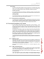
4.2.6. Switching operations flowchart in X-Y mode
To better understand the viewing and switching sequence in TAKE and
AUTOTAKE modes, please study the below diagrams.
TAKE mode
source
button
pressed
select or
deselect
destinations
viewing
source
connections
previewing
connections
nothing pressed for 3 sec
idle
connections
realized
TAKE
mode
TAKE
button
pressed
nothing pressed for 3 sec
destination
button
pressed
viewing
destination
connection
Figure 4-1. Switching flowchart in TAKE mode
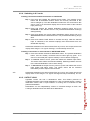
AUTOTAKE mode
destination
button
pressed
idle
AUTOTAKE
mode
viewing last destination’s
connection
change or
deselect
source
connection
realized
Figure 4-2. Switching flowchart in AUTOTAKE mode
Section 4. Operation
Page 15 / 32
4.2.7. Preset operations
Lightware matrix routers have 32 user programmable presets. Each preset stores a
configuration regarding all input connections and mute state for all outputs. All
presets are stored in a non volatile memory; the router keeps presets even in case
of power down. Memory numbers are assigned to source buttons 1..16 on MXRCP16 and 1..32 on MX-RCP32.
Saving a Preset in TAKE mode
Step 1. Create the desired connections which have to be saved.
Step 2. Press and release the SAVE PRESET button.
Step 3. Press and release a source button according to the desired memory
address (source 1 to 16 or to 32).
Step 4. Press and release TAKE button. Now the current configuration is stored in
the selected memory.
Info
Preset save action always stores the current configuration for all outputs including
mute state, but ignoring lock state.
Loading a Preset in TAKE mode
Step 1. Press and release LOAD PRESET button.
Step 2. Press and release a source button according to the desired memory
address (source 1 to 16 or to 32).
Step 3. Press and release TAKE button. Now the selected preset is loaded.
Info
Loading a preset modifies all output states that are not currently locked.
Saving a Preset in AUTOTAKE mode
Step 1. Create the desired connections which have to be saved.
Step 2. Press and release SAVE PRESET button.
Step 3. Press and release a source button according to the desired memory
address (source 1 to 16 or to 32). Now the current configuration is stored in
the selected memory.
Info
Preset save action always stores the current configuration for all outputs including
mute state, but ignoring lock state.
Loading a Preset in AUTOTAKE mode
Step 1. Press and release LOAD PRESET button.
Step 2. Press and release a source button according to the desired memory
address (source 1 to 16 or to 32). Now the selected preset is loaded.
Info
Page 16 / 32
Loading a preset modifies all output states that are not currently locked.
Section 4. Operation
MX-RCP32
User’s Manual Rev. 0.8
4.3. Front panel operations in Y mode
The Y mode is active when the Y button lights on the front panel. While the Y
button is pressed, the affected output can be selected. After the button is released,
every button is dedicated to inputs of the matrix router that the RCP is connected
to. Pressing an I/O button while the Y button is released executes the switching at
once on the last selected output. The affected output can be easily changed by
pressing and holding the Y button, and pressing the port number of the desired
output.
All buttons are dedicated to inputs when the Y button is released. All buttons are
dedicated to outputs while the Y button is pressed. This way sources and
destinations can be selected from port 1-32 with MX-RCP16 and 1-64 with
MX-RCP32.
TAKE / AUTO, Load Preset and Save Preset buttons are disabled in this mode.
4.3.1. CONTROL LOCK
Front panel button operations on the RCP unit can be enabled or disabled using
CONTROL LOCK button. This does not affect the front panel control on the router
itself, neither the Serial nor Ethernet control from another RCP unit. If the button is
not illuminated, front panel button operations are enabled. If it illuminates red
continuously, front panel operations are inhibited.
Press and hold the CONTROL LOCK button for 3 seconds to toggle the control
lock state.
4.3.2. Switching in Y mode
Step 1. Press and keep pressed the Y-mode button. The button of the affected
output port lights.
Step 2. To change the affected output port, hold the Y-mode button down and
press the desired output number.
Step 3. Release the Y-mode button. The button of the currently connected input
port lights up.
Step 4. To change the source, press any of the numbered buttons. (1-32 on the
MX-RCP16 and 1-64 on the MX-RCP32.)
Step 5. The switching is done at once. The newly selected source is connected to
the affected destination.
Section 4. Operation
Page 17 / 32
4.3.3. Switching operations flowchart in Y mode
press any
numbered
button
Y-mode
button
held down
idle
Y mode
affected
destination
changed
Y-mode
button
released
showing
affected
destination
showing affected destination’s connection
press any
numbered
button
source changed
on affected
destination
4.4. Front panel operations in SALVO mode
Salvo mode is active when the SALVO button lights on the front panel. In this
mode the buttons are not dedicated to an input or an output port of the connected
matrix. Each button can have its own command sequence that is executed if the
button is pressed. The command sequences can be programmed to the RCP with
the Matrix Controller software.
TAKE / AUTO, Load Preset and Save Preset buttons are disabled in this mode.
Verified salvo mode
The command sequence can contain any switching command according to the
selected protocol (Lightware or secondary protocol). The RCP checks the
response from the matrix and verifies if the crosspoint state matches with the
issued commands. The button will light only if all the commands were successfully
executed, and the matrix configuration is in accordance with the command
sequence. If the crosspoint configuration does not match with the sent commands,
the button blinks.
Free salvo mode
The command sequence can contain anything. The response is not monitored, the
last pressed salvo button lights until another is pressed.
4.4.1. CONTROL LOCK
Front panel button operations on the RCP unit can be enabled or disabled using
CONTROL LOCK button. This does not affect the front panel control on the router
itself, neither the Serial nor Ethernet control from another RCP unit. If the button is
not illuminated, front panel button operations are enabled. If it illuminates red
continuously, front panel operations are inhibited.
Press and hold the CONTROL LOCK button for 3 seconds to toggle the control
lock state.
Page 18 / 32
Section 4. Operation
MX-RCP32
User’s Manual Rev. 0.8
4.4.2. Executing salvos
Step 1. Press and release the SALVO mode button to enter Salvo mode.
Step 2. Press and release the desired salvo button. (1-32 on the MX-RCP16 and
1-64 on the MX-RCP32.)
Step 3. The button flashes to indicate press, and the stored command sequence is
sent to the matrix router.
a) In verified salvo mode the pressed button stays illuminated only if
the command sequence contained only switch commands, and the
response from the matrix meets the required configuration.
Otherwise the pressed button blinks.
If the salvo was executed correctly, but later the matrix
configuration is changed (e.g. switching is done directly on the
router’s front panel), than the salvo button starts to blink. This
indicates that the current crosspoint configuration does not match
the previously selected salvo.
If the crosspoint configuration changes to a state that meets the
last executed salvo, then the salvo button changes to continuous
illumination.
b) In free salvo mode the pressed button stays illuminated
disregarding the response.
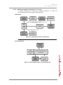
4.4.3. Verified salvo operations flowchart
other
controller
salvo button
pressed
idle
SALVO
mode
Section 4. Operation
matrix router
executing
stored salvo
crosspoint
configuration
mismatch
crosspoint
configuration
match
showing last executed salvo validity
(blink if invalid, continuous if valid)
Page 19 / 32
4.5. Operation in UDC mode
The UDC protocol is developed to integrate with third party solutions. This way the
front panel operations depend on the third party system, thus not described in this
documentation.
See section XX about the UDC protocol.
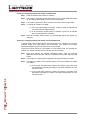
5. Using Lightware Matrix Controller
5.1. Installing the Matrix Controller software
Step 1. Run Installer_LW_matrix_controller_v3_2_4.exe
Step 2. Select destination folder and click Install (Using the default path is highly
recommended)
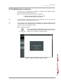
Step 3. If you want to create desktop icon click Yes in the next pop-up window:
Step 4. After finishing the installation the following message appears:
Step 5. To run Lightware matrix control software find the shortcut icon in
Start menu Programs Lightware LW_matrix_controller_vXXX or on
the desktop, and double click:
Uninstalling
To uninstall the control software double click on: Start menu Programs
Lightware Uninstall_LW_matrix_controller_vXXX.exe
Page 20 / 32
Section 5. Using Lightware Matrix Controller
MX-RCP32
User’s Manual Rev. 0.8
5.2. Establishing the connection
The unit can be controlled from a Windows computer using Lightware Matrix
Controller software through Ethernet port.
Step 1. Connect the matrix switcher and the computer via
Ethernet through a LAN hub, switch or router
Ethernet directly (with cross UTP cable)
Info
If the connection is made through the router’s Ethernet port, be sure that the
computer is in the same network as the router.
Info
If the computer has multiple Ethernet connections (for example WiFi and LAN
connections are used simultaneously) you will have to know the IP address for the
one that is used for controlling the matrix.
Step 2. Start the application
To run the CONTROL SOFTWARE double click on the icon
of the software on the desktop or select proper shortcut from
Start Menu Programs Lightware folder.
Figure 5-1. Matrix Controller software startup
Section 5. Using Lightware Matrix Controller
Page 21 / 32
Step 3. The Find dialog appears automatically
The software picks the primary Ethernet interface, and shows the available
Lightware devices on that port. The device type and the serial number are
displayed automatically. Click the desired device, to highlight it.
If the computer has more Ethernet ports (for example WiFi and LAN connections
are used simultaneously), you must select the one that is used to control the router
from the drop-down list. If you are unsure which one to use, try to search for
devices on all of them.
Figure 5-2. Ethernet connection
Step 4. Click on the Connect button to connect to the device
Info:
If the router is not listed in the “available devices on Ethernet” box, try searching
again, or see check the other Ethernet interfaces as well.
Info:
Only one user is allowed to connect to the RCP unit via Ethernet.
Info:
Be sure that the firewall is not blocking the application!
Step 5. The RCP enters configuration mode when the software connects to it. The
three operation mode buttons are blinking simultaneously to indicate this.
While in configuration mode, the front panel operations are ignored on the
RCP unit.
Page 22 / 32
Section 5. Using Lightware Matrix Controller
MX-RCP32
User’s Manual Rev. 0.8
When the Lightware Matrix Controller finds the hardware, it determines the product
type, and the control menu appears.
5.3. Control menu
Figure 5-3. RCP control menu
5.3.1. Controlled target
In the upper frame, the target IP address and port number of the matrix router or
the UDC server is displayed. The currently set target is inquired and displayed
upon connection.
To change the controlled target, type the IP address and port, then press Apply.
The IP address must be typed with all leading zeros in the dot-decimal notation.
(e.g. write 192.168.002.205 instead of 192.168.2.205)
The IP address and port of a matrix router can be checked on the front panel LCD
on the matrices or the devices can be discovered with the FIND dialog in the Matrix
Controller software.
5.3.2. Salvo commands
In the lower frame the SALVO command sequences can be set up. Salvo
commands can be used to execute a sequence of commands with one press of a
button. One command sequence is stored for each button.
The RCP stores a total of 128 command sequences: 64 for Lightware protocol and
another 64 for the secondary protocol. The control software displays if Lightware or
Secondary protocol is active for remote controlling, and shows only the 64 salvos
that belong to the actual protocol. The other 64 salvos are not accessible and not
affected.
Storing salvos
Each salvo memory can store a maximum is 512 character long command
sequence. Each command has to be typed including { } brackets. Any commands
can be stored, but when verified salvo mode is used, only switching commands are
sent. If a stored salvo contains switching and other commands as well, the nonswitching commands are omitted. When using free salvo mode, any string in the
salvo memory is sent to the matrix.
Section 5. Using Lightware Matrix Controller
Page 23 / 32
Salvo commands are sent as a batch. In most cases, batch commands are
processed just as if they were sent one by one, but for switching commands, the
router groups them, and executes switching in one step. The grouping is done only
if the switching commands are received after each other, without any interruption
(e.g. other command sent between switch commands). For example the salvo
{02@01}{05@04} results in group switching but the salvo {02@01}{+06}{05@04}
does not resulted group switching, because another command get between.
5.4. Status menu
Basic device information, such as the RCP unit’s IP address and the serial number
are displayed in this window. The firmware versions can be checked in the lower
frame.
5.4.1. IP settings
The RCP unit’s IP settings can be viewed by clicking on the “Serial and IP
Settings...” button.
These settings are independent from the controlled target settings. However, the
RCP unit has to be in the same subnet as the controlled matrix. The RCP unit’s
port number is used only by the control software when connecting to the RCP unit.
The controlled target’s IP address and port number can be set in the control menu.
See section 5.3.1 for more information.
Page 24 / 32
Section 5. Using Lightware Matrix Controller
MX-RCP32
User’s Manual Rev. 0.8
Obtain IP address automatically
By selecting the “Obtain IP address automatically” option, the RCP unit gets the IP
address from the DHCP server on the LAN, or if DHCP server is not present, it gets
an AutoIP address from the 169.254.xxx.xxx domain.
Fix IP configuration
In this case, the RCP unit has an IP address configuration set up by the
user/administrator. The earlier saved configuration is shown in brackets.
Step 1. Select the “Fix IP configuration” option.
Step 2. Type in the IP address, select the desired subnet mask and type in the
gateway IP address.
Step 3. Click on “Apply Settings” button. Depending on the modified settings, you
might need to restart the RCP and the Matrix Controller Software.
Info:
The “Load Default” button loads the factory default IP settings to the fields, which
contain a fix configuration:
IP Address:
192.168.254.254
Subnet Mask:
255.255.0.0
Default Gateway: 0.0.0.0
IP port settings
The RCP unit can be accessed via this TCP/IP port number with TCP connection.
This number can be modified to any number between 1025 - 65535 except the
followings: 9999, 14000 - 14009, 30704, and 30718.
Info:
This port number is independent from the target port number.
Info:
The IP port number is 10001 by default.
Section 5. Using Lightware Matrix Controller
Page 25 / 32
6. Programmer’s reference
6.1. Matrix control protocols
When protocol 1, 2, 4 or 5 are set, the RCP unit sends and accepts commands that
are described in the user’s manual of Lightware matrix routers.
6.2. UDC protocol
In UDC mode the RCP unit connects to a TCP server on a specified IP address
and port. See section 5.3.1 about configuring the target. The RCP unit sends a
command if a button is pressed down or released. The LEDs can be switched
ON/OFF/BLINK by sending command to the RCP.
Buttons and LEDs are referred with their number as 1..32 on MX-RCP16 and 1..64
on MX-RCP32. The special function buttons and LEDs are referred as F1..F8 on
both units.
Legend for protocol
<BTN>
=
button name 1..64 or F1..F8 (in ASCII format)
<LED>
=
LED name 1..64 or F1..F8 (in ASCII format)
CrLf
=
Carriage return, Line feed (0x0D, 0x0A)
●
=
space character (0x20)
→
=
each command issued by the TCP server, sent to the RCP unit
←
=
each response received by the TCP server, sent by the RCP unit
6.2.1. Sent responses
Button pressed down
Format
Response {D<BTN>}CrLf
Example
← (D5)
Button released up
Format
Response {U<BTN>}CrLf
Example
← (UF3)
6.2.2. Accepted commands
Turn LED on
Format
Command {on@<LED>}CrLf
Example
→ {ON@6}
Turn LED off
Format
Command {off@<LED>}CrLf
Example
→ {OFF@4}
Blink LED
Format
Command {blink@<LED>}CrLf
Page 26 / 32
Example
→ {BLINK@F2}
Section 6. Programmer’s reference
MX-RCP32
User’s Manual Rev. 0.8
7. Specifications
General
Compliance ..................................................................................... CE, UL, FCC
EMI/EMC ..................................................................... EN 55103-1, EN 55103-2
Safety ....................................................................................... EN 60065 Class I
Warranty ................................................................................................... 3 years
Operating temperature ................................................................. -20°C ~ +50°C
Humidity ........................................................................................... 10 ~ 90% RH
Power
Power adaptor (wall plug type) ................ 100-240 V AC; 50~60 Hz / 5V DC; 1 A
Power consumption ......................................................... max 2 W (7 BTU/hour)
DC power connector .......................................................... 2.5/5.5 mm barrel plug
Enclosure (MX-RCP16)
Rack mountable ............................................................................... Yes, 1U high
Material ............................................................................................... 1 mm steel
Dimensions ............. 446/482W x 55D x 44H mm (17.6/19W x 2.2D x 1.7H inch)
Net Weight ..................................................................................................... TBD
Enclosure (MX-RCP32)
Rack mountable ............................................................................... Yes, 2U high
Material ............................................................................................... 1 mm steel
Dimensions ............. 446/482W x 55D x 89H mm (17.6/19W x 2.2D x 3.5H inch)
Net Weight ..................................................................................................... TBD
Network connection
Ethernet port connector ................................................... RJ45 female connector
Ethernet protocol .................................................... TCP/IP, HTTP, TFTP, Telnet
IP address assignment .................................... fixed, DHCP, BOOTP, and AutoIP
Section 7. Specifications
Page 27 / 32
7.1. Mechanical Drawings (MX-RCP16)
Front View
482 mm
43.9 mm
Rear View
43.5 mm
446 mm
Top View
56.2 mm
55 mm
2 mm
Side View
43.5 mm
43.9 mm
55 mm
56.2 mm
Page 28 / 32
Section 7. Specifications
MX-RCP32
User’s Manual Rev. 0.8
7.2. Mechanical Drawings (MX-RCP32)
Front View
482 mm
88.5 mm
Rear View
88.1 mm
446 mm
Top View
446 mm
56.2 mm
55 mm
482 mm
2 mm
Side View
88.5 mm
88.1 mm
55 mm
56.2 mm
Section 7. Specifications
Page 29 / 32
8. Version applicability
This User’s Manual applies to the following versions of the mentioned software,
firmware and hardware:
version
Lightware Matrix Controller software
3.2.4
Lightware Bootloader software
3.2.1
MX-RCP firmware
1.2.8
MX-RCP Web Server
1.0.0
MX-RCP Web Content
DISABLED
MC-RCP card hardware
PCB 1.1
Control Panel firmware (MX-CP1)
1.0.4
RCP enclosure
1.0
9. Warranty
Lightware Visual Engineering warrants this product against defects in materials
and workmanship for a period of three years from the date of purchase.
The customer shall pay shipping charges when unit is returned for repair.
Lightware will cover shipping charges for return shipments to customers.
In case of defect please call your local representative, or Lightware at
Lightware Visual Engineering
1071. Budapest Peterdy str. 15, HUNGARY
Page 30 / 32
Tel.:
+36 1 889 6177
Fax:
+36 1 342 9903
E-mail:
[email protected]
Section 8. Version applicability
MX-RCP32
User’s Manual Rev. 0.8
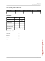
10. Quality Check Record
Model name
Serial number
Date of manufacture
Checked
Hardware
Module
Hardware
Firmware
RCP board
CPU &
Control Panel 1
Control Panel 2
(only for MX-RCP32)
LAN control server
MAC address
:
:
:
:
:
Electrical check
+3.3V; +5V
CPU Live
Buttons
LAN
Section 10. Quality Check Record
Page 31 / 32
11. Document revision history
Document
Release Date
Changes
Checked by
Rev. 0.8
01-11-2010
preliminary edition
Tamas Lehel
Rev. 0.1
20-09-2010
draft
-
Rev. 1.0
Page 32 / 32
Section 11. Document revision history