1
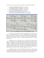
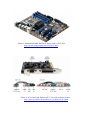
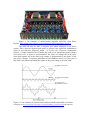
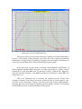
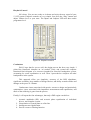
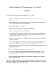
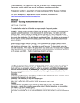
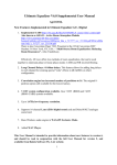
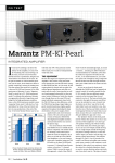
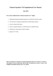
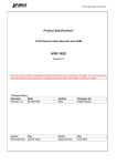
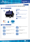
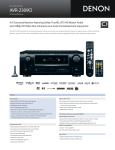
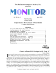
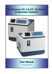
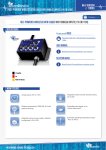
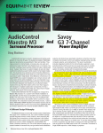
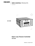
DSP-PC for 5.1 Home Theatre System
By Bohdan Raczynski
Bodzio Software Pty. Ltd.
Is it becoming quite common these days to see a personal computer sitting
somewhere in the audio-video room, and providing centralized audio/video server
capabilities. Additional functionality described in this article, brings the audio
performance of an active 5.1 HT system to a new level.
Basic functional concept
DSP-based audio systems, such as Ultimate Equalizer (UE), offer attractive,
new sound-processing functions, which are not available in traditional passivecrossover loudspeaker systems. The four most important DSP contributions would be:
1. Acoustic amplitude (SPL) and acoustic phase equalization of individual
drivers, and complete system.
2. Linearization of system phase to a flat line.
3. Intelligent room equalization.
4. Precise crossover filtering function.
It is perhaps worth mentioning at this point, that active loudspeaker system
discard all issues related to impedance of the driver, making the design of such
loudspeaker system significantly less complicated and more accurate.
As a general concept, a device described above, and implemented as a
Windows © software program, can be running on a personal computer, equipped with
a suitable sound card(s). This device would be used to compliment Windows Media
Player© for audio only sessions, or Windows Media Player© for a video sessions
running on your PC.
Connectivity
Windows 7 Home Premium©, Ultimate, and Enterprise come with DVD
playback capability built in. If you're running Windows 7 Home Basic or Starter, you
can upgrade your edition of Windows 7 to add full DVD capability.
From the connectivity point of view, it means, that your Windows7- based PC
can play a DVD and decode 5.1 Dolby Digital© sound and output the analogue audio
via the 6-channel built-in motherboard Realtek sound system, thus making it available
to for external processing. Obviously, using an external Blu-ray 3D DVD player is
another alternative.
This is where the new DSP-PC device comes in. As the 5.1 surround sound
DSP processor, it comes with 6 analogue inputs, ready to accept the decoded movie
sound tracks. After all processing is done, the DSP processor puts out up to 16
channels for individual drivers built into the 5.1 surround system loudspeakers.
For instance, your surround sound system could have the following components:
1.
2.
3.
4.
5.
6.
7.
front-left (FL) loudspeaker designed as 3-way system.
front-right (FR) loudspeaker designed as 3-way system.
rear-left (RL) loudspeaker designed as 2-way system.
rear-right (RR) loudspeaker designed as 2-way system.
centre CT) loudspeaker designed as 3-way system.
left-subwoofer (LS) loudspeaker designed as 1-way system.
right-subwoofer (RS) loudspeaker designed as 1-way system.
Figure 1. Example of a 15-channel surround sound system design.
This system would consume 15 sound card output channels. Please note, that
there are two subwoofers in the system. This configuration may come very handy, if
decide to augment the bottom-end of your stereo configuration. Our DSP processor
should have the ability to link the LS subwoofer to FL channel and link the RS
subwoofer to FR channel. Obviously, providing appropriate frequency and phase
characteristics.
Additional aspect of connectivity can be exploited by creating “special
effects”. For instance, when using your system for stereo listening (on the top of
subwoofer augmentation ), you can utilize RR and RL channels as well. One option
would be to band-limit the RR and RL channels and add some time delay to these
channels, so when played in normal stere-mode, such configuration would create the
overall effect of much larger venue. You could also connect the RR and RL speakers
180deg out of phase for further experimentation. There are quite a few possibilities to
explore and create your own version of acoustic signature for the venue.
It should be clear by now, that the DSP-PC may require at least as many
individual amplifier modules as there are drivers in the whole system. Some designs
will employ less amplifiers, if there are dual loudspeakers in one enclosure, that can
be powered from the same amplifier module. All choices are up to the designer.
An example of another, but smaller, 14-amp-channel 5.1 HT system is conceptually
shown on Figure 2.
Figure 2. 14-amp-channel, surround sound DSP-PC based loudspeaker system.
DSP-PC hardware implementation
The Ultimate Equalizer is an advanced, complete software package, allowing
you to measure loudspeaker SPL, process the results of measurements, model
diffraction effects, design 6in/16out loudspeaker setup and finally, play the sound
through it as a fully equalized crossover, with an addition of intelligent room
equalization.
This is actually quite a lot of functions. However, this article will not involve
loudspeaker SPL measurements performed by the Ultimate Equalizer (2). The
intended focus of this article is on the design of the 5.1 HT system.
The program has been written using the new, “exclusive mode”, WASAPI
audio engine and runs on Windows 7/64-bit and Windows 7/32-bit operating system.
The motherboard (eg: MSI X58 Pro-E Series, shown on Figure 3) requires two PCI
slots, as there are two Delta1010LT sound cards used. This configuration will allow
you to design and run loudspeaker system with 6 inputs and 16 outputs – just right for
a large 5.1 HT system. For additional information about synchronizing Delta1010LT
sound cards please consult reference (1).
Figure 3. Motherboard MSI X58 Pro-E Series with 2 x PCI slots.
http://au.msi.com/product/mb/X58-Pro-E.html
Figure 4. PCI sound card: Delta1010LT. You will need two of these.
http://www.m-audio.com/products/en_us/Delta1010LT.html
Figure 5. An example of multi-channel amplifier MA1240, from PartsExpress. http://www.parts-express.com/pe/showdetl.cfm?Partnumber=300-815
The MA1240 may be able to surprise you, when employed in an active
system. This is because required peak power is greater if the signal has simultaneous
peaks in two different frequency bands - as in the case of passive loudspeaker
systems. A single amplifier has to handle the peak power when both signal voltages
are at their crest; as power is proportional to the square of voltage, the peak power
when both signals are at the same peak voltage is proportional to the square of the
sum of the voltages. If separate amplifiers for each band are used, (as in the case of
MA1240) each must only handle the square of the peak voltage in its own band.
Figure 6. Crest voltages for separate and combined 100Hz and 500Hz waveforms.
(adopted from http://clas.mq.edu.au/acoustics/waveforms/adding_waveforms.html and modified).
For instance, please assume 8ohm load impedance, and consult Figure 6 above.
1. Single amplifier is required to deliver audio power to a passive loudspeaker
system with crossover with crossover at 300Hz. Woofer branch requires 20V
and midrange branch requires 10V maximum voltage level. Amplifier
satisfying these requirements would have to be able to deliver 56Watts of
undistorted power, at clipping level of 30Volts.
2. Bi-amped system, is required to deliver audio power to an active loudspeaker
system with crossover at 300Hz. Woofer branch requires 20V and midrange
branch requires 10V maximum voltage level (same as above).
Here, the woofer amplifier only needs to deliver 24.5Watts at clipping level of
20Volts. Midrange amplifier is required to deliver 6.2 Watts at clipping level of
10Volts.
This is very important aspect of active systems in general – they require much
smaller amplifier to play as loud as comparable passive systems. In the example
above, woofer requires only 44% of the passive amplifier power. It would be fair to
say following the example above, that 40Watt active system woofer amplifier would
be equivalent to 90Watt amplifier in passive system.
5.1 HT system design process in details
Imagine, you can have a large selection of filter configurations and types, and
the ability to cascade them any way you like. On the top of this, you are able to
cascade other filtering elements, like notches, shelving and peaking elements with
adjustable Q-factor. Each one of these long chains can be applied as a filtering
channel for individual driver in the enclosure. In order to visualize the whole
crossover, you would simply pick-and-place filtering elements from the available tray
of component, and then place and link them on the screen to effectively built the
whole crossover as a block diagram with interconnected filtering elements. The “tray”
is shown below. To keep things simple, there are only three active elements, using
which you can built the entire crossover.
First, the “Loudspeaker” element – incorporates measured driver file name,
equalization frequency range, channel delay, channel phasing, channel gain and sound
card output port assignment data. Equalization of the loudspeaker is implemented as
inverted Hilbert-Bode Transfrom (HBT) function. It is very effective in equalizing the
measured SPL to a flat line, and equalizing the measured phase to straight, line as
well. Final phase equalization to a flat line is performed by running the DSP-PC in
“Linear-Phase Mode”. This way the acoustical transfer functions of your loudspeaker
(or frequency and phase responses if you like) are both flat lines. Such loudspeaker
will reproduce square waves at the listening location.
Next, the “Filter” element – incorporates a large selection of filter
configurations and types, cut-off frequency, and also gain and Q-factor of notch/peak
and shelving elements. As mentioned above, you can cascade a number of these
elements to make filtering channels for each driver in the enclosure.
Here is an example of frequency response of the filtering element described above.
And finally the “Room EQ” element. This element is more complex, and
allows you to incorporate minimum-phase room equalization for each enclosure. This
element combines up to 6 measured room SPL responses to calculate spatial average
and then calculates room correction function to be applied to this particular
loudspeaker. Typically, you would focus on the low-end frequency range, say below
150Hz, and apply the room correction carefully, with caution, to avoid overequalization.
The “Input” element is not involved in calculation of transfer functions – it’s only
purpose is to allow you to select sound card port for the selected loudspeaker.
The equalization process incorporated in Ultimate Equalizer was described in
details in Audio Xpress June 2010, therefore, it will not be presented in details here.
However, as a remainder, please consider Figure 7 below. Depicted here are the
following curves:
1.
2.
3.
4.
5.
Green curve – SPL of the measured driver
Dark Blue curve – SPL correction curve, calculated by inverted HBT
Red curve – filter transfer function – 2nd order, 1000Hz, Butterworth.
Pink curve – final equalized SPL. Equalization frequency range 60Hz-6000Hz.
Grey curve – final equalized phase. Equalization frequency range as above.
The final, flat phase response is accomplished by employing time-inverted
filtering method. This example shows the crossover and equalization design for the
woofer drivers in the Front-Left speaker system.
Figure 7. Woofer filtering and equalization design.
Figure 8. Front-Left loudspeaker system, fully equalized SPL (pink curve) and
phase (grey curve) transfer functions.
The process I have just described, needs to be applied to all other loudspeakers
in your 5.1 HT system. Having finished, you will be left with a superbly performing
loudspeakers, having frequency and phase responses flat and possibly extended by an
octave into low and high-ends of the old operating frequency range.
In the next step, you may want to audition each loudspeaker individually, in
their designated location. While doing this, you may want to adjust “voicing” of each
loudspeaker to your individual taste, by inserting “voicing” elements like: high-pass,
low-pass shelving elements, or broadband parametric-Q elements to obtain BBC dip
effect, and so on.
This is an important step in tweaking the complete system, because flat
frequency response is one thing, but whole system also has to sound right for your
own ears as well. Personally, I always enjoy this part of the system implementation,
knowing, that I start from perfectly optimized system already, and this is just putting
the final touches on the overall performance of he system.
Figure 9. Complete Front-Left channel loudspeaker system.
Similar process would be applied to midrange and tweeter drivers, and final
outcome is depicted on Figure 7 and Figure 8. As you can see, I employed Linkwitz,
2nd order filters with crossover frequencies of 500Hz and 5000Hz. In this design, I
have included RoomEQ component as well, and it is available for each of the
loudspeaker boxes in the HT system, giving you six built-in room equalizers to work
with. Also, one shelving element is included for in-room voicing tweaks on the bass
side.
Sensible Room Equalization
Before I close the design part of this process, it is worth to measure the inroom SPL performance of each loudspeaker. The Ultimate Equalizer is furnished with
it’s own MLS measurement system, so this task is relatively simple.
The goal of this design phase is to check for any obnoxious room modes.
Typical audio/visual room will exhibit modal resonances, which essentially add
unwanted coloration to the sound. You can measure the SPL in several (up to 6)
locations and automatically obtain averaged SPL as well.
The effect of gentle room equalization can be observed on a subwoofer
measured in-room – see Figure 10. Here, the room modes result in excessive SPL
from 25-55Hz. For instance, 32Hz tone will sound disproportionably louder than
20Hz. Applying sensible room equalization (blue curve) will result in flattening the
unwanted bumps and effectively extending flat, in-room frequency response to
17 - 70Hz.
Figure 10. Room equalization
THX Certification
Well, this is not about getting the “official” THX© certification, but it’s
perhaps worth to consider, if your design would qualify as a commercial THX system.
As you may imagine, directors and movie producers have every intention to deliver a
high quality sound and picture to your living room, so that impact of both is exactly as
they intended.
To accomplish this on the acoustical side, you need to recreate the bandwidth,
and intended SPL levels for the surround and subwoofer loudspeakers.
The THX defines “0dB” reference level to be 85dB SPL, basically at your
listening position. And then you must provide 20dB headroom. Therefore, your
surround speakers should be able to provide a peak, undistorted sound at 105dB SPL
level.
Subwoofer requirements are even more demanding. The reference level is
+10dB SPL, and the peak is elevated to 115dB SPL. This is seriously loud.
However, accommodating these requirements is easily accomplished by
selecting appropriate power amplifiers and loudspeaker drivers, to attain the required
SPL levels. Our multi-channel, MA1240a amplifier would possibly suffice for
smaller-to-average size room, but if you have larger size room, then you may need to
beef-up on the audio power. The same goes for subwoofers.
Playback Control
Job’s done. You are now ready to sit down and enjoy the new sound of your
5.1 HT system. Playback controls are very simple. Just press the “Play” button and
adjust Volume level to your taste. The Inputs and Outputs LED will show audio
programme level.
Figure 10. Playback controls
Conclusions
Well, I hope that for you as well, the design process has been very simple. I
picked the functional elements on “as needed” basis, and created the complete
functional block diagram of a crossover intended for front-left loudspeaker system,
accounting for room equalization as well. Then I proceeded to complete all other
loudspeakers in the system.
This approach offers you simplicity, accuracy of the DSP algorithms,
significant versatility, large number of design choices, and ability to make tweaks and
changes at the press of a button.
Cumbersome issues associated with passive crossover design and particularly
optimization, issues associated with impedance measurement and equalization, and
much of the soldering is gone from the process.
Finally, I will repeat the four advantages, that only a DSP engine can deliver:
1. Acoustic amplitude (SPL) and acoustic phase equalization of individual
drivers, and complete system.
2. Linearization of system phase to a flat line.
3. Intelligent room equalization.
4. Precise crossover filtering function.
References.
1. Synchronizing Delta1010LT sound cards, Bohdan Raczynski, Bodzio
Software Pty. Ltd. 2011.
2. Ultimate Equalizer User’s Manual, John Kreskovsky, Music and Design.
2011.