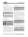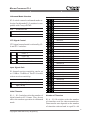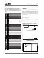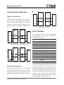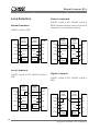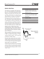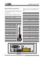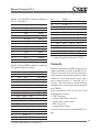
1
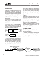
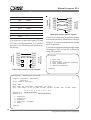
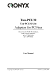
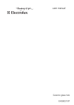
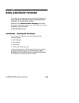
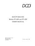
Modem-converter E1-L
User‘s Guide
1234567890123456789012345678901212345678901234567890123456789012123456789012345678901234567890121234567
1234567890123456789012345678901212345678901234567890123456789012123456789012345678901234567890121234567
Modem E1
Features
Contents
• E1 G703/G704 channel
Description
• Distance up to 1.5 km
• V.35/RS-530/RS-449/RS-232/X.21/
Ethernet user data interface
• Data rate from 64 kbps up to 2048
kbps
• Programmable timeslot assignment
• G.703 2048 kbps unframed mode
• Cronyx PCM2 compatibility
• CAS and CRC4 framing
• Synchronization from digital interface (DTE emulation)
• Digital, local and remote loopbacks
• Integrated BER tester
• RS-232 Control port
• Dry contacts alarm interface
Package Contents
Specifications
Ordering Code
Controls and Indicators
Controls on Front Panel
Front Panel Indicators
DIP Switches
Jumpers
Line Impedance
Transmit Clock Inversion
Clock Source Selection
Single clock source
Separate clock sources
Loop Selection
Normal Operation
Local Loopback
Remote Loopback
Digital Loopback
• Stand-alone or rack-mount (19’’3U)
Alarm Interface
• AC or DC power
Rear Panel Connectors
• The certificate No. ÎÑ/1-ÑÏÄ-19
ÑÑÝ of the Russian Ministry of
Communications (registration
number ÐÎÑÑ RU.0001.01ÝÑ00)
Copyright © 1998-2000 Cronyx Engineering
Console
Cables Wiring
1.0E / 01.12.2000
1
MODEM-CONVERTER E1-L
12345678901234567890123456789012123456789012345678901234567890121234567890123456789012345678901212345678901234567890123456789012123456789
12345678901234567890123456789012123456789012345678901234567890121234567890123456789012345678901212345678901234567890123456789012123456789
Description
Cronyx - E1-L is a multipurpose access unit
for Fractional E1 services. As a rate and
interface converter it accepts digital interface data at any multiple rate of 64 kbps up
to 2048 kbps and places it into E1 frame
using required number of timeslots or the
whole bandwidth of 2048 kbps in unframed mode.
As a modem it is capable to operate at distances up to 1.5 km over twisted pair or
coaxial cable.
E1-L device is available as stand-alone unit
or as a card for 19’’ 3U Cronyx rack. Rack
mount modem consists of two cards one
of which is set on the front side and the
other on the back side of the rack.
V.35,
Ethernet
etc.
Digital
Interface
To terminal
RS-232
E1
Interface
Channel E1
(up to
1.5 km)
Control port
It can be ordered with RS-530, RS-232,
V.35 or X.21 interfaces, ended with standard connectors. Multi-standard interface
option with HDB44 connector is also available. The type of interface in this case is
determined by adapter cable: RS-232, RS530, RS-449, RS-442, V.35 or X.21.
V.35 / RS-530 / RS-232
64...2048
kbps
Router
2
E1-L
Device can be ordered with Ethernet interface. A couple of devices with this interface form a remote bridge for two LANs.
Configuration can be performed via RS232 control port or by DIP switches. Configuration parameters are stored in
NVRAM.
Maintenance capabilities include user activated local and remote loopbacks on the
E1 link. In-band management of the remote unit can be performed by using the
spare bits (Sa) on timeslot 0 (in compliance with G.704 recommendation).
Modem E1-L is also available as a card for
Intel-compatible computers (Cronyx-Tau/
E1, Cronyx Tau-PCI/E1).
Package Contents
The following is a check list for the contents of your package:
• Modem E1-L in ordered configuration
• Removable terminal block for E1 line
• Power supply cord (for AC power
models)
• User manual
Network
Е1
E1-L
Copyright © 1998-2000 Cronyx Engineering
MODEM-CONVERTER E1-L
12345678901234567890123456789012123456789012345678901234567890121234567890123456789012345678901212345678901234567890123456789012123456789
12345678901234567890123456789012123456789012345678901234567890121234567890123456789012345678901212345678901234567890123456789012123456789
Specifications
Digital Interface
Data Transfer Rate.............................. N x 64 kbps or up to 2048 kbps in unframed
mode
Clock Options .................................... TXC, RXC, ETC, ERC
ModemControl Signals ...................... DTR, DSR, CTS, RTS, CD
E1 Interface
Line Coding ....................................... HDB3
Line Impedance .................................. 120 Ohm Balanced (Twisted Pair) or
75 Ohm Unbalanced (Coax Cable)
Input Signal Attenuation Range ......... from 0 to –30 dB, up to 1.5 km of 22 AWG
(0.6 mm) twisted pair
Transmit Timing Sources ................... INT (Internal Oscillator)
RCV (Receiver)
EXT (Digital Interface)
Jitter Attenuator .................................. Both in receive & transmit path,
120 UIpp attenuation
Frame structure .................................. G.704 or unframed mode
Multiframes ........................................ CRC4, CAS(G.704)
Frequencies offset Adjustment ........... Controlled Slip Buffer
Connector Type .................................. Terminal Block
Alarm Interface
Relay Contact Current ........................ up to 250mA
Relay Contact Voltage ........................ up to 175V DC
Control Port
Interface ............................................. RS-232
Protocol .............................................. Async 19200 bps, 8 bit/char , 1 stop bit, no
parity
Connector Type .................................. DB9
Diagnostics
Loopbacks .......................................... Digital, local (G.703 line on local unit),
remote (G.703 line on remote unit), selected by
front panel switches or via control port
BER Tester.......................................... Activated by front panel switch or via control
port
Copyright © 1998-2000 Cronyx Engineering
3
MODEM-CONVERTER E1-L
12345678901234567890123456789012123456789012345678901234567890121234567890123456789012345678901212345678901234567890123456789012123456789
12345678901234567890123456789012123456789012345678901234567890121234567890123456789012345678901212345678901234567890123456789012123456789
Ordering Code
E1-L / B-M-AC
Power supply:
AC – ~220V,
DC – =60V (for stand-alone
unit only)
Digital interface:
M – multistandard
V35 – V.35
232 – RS-232
530 – RS-530
ETH – Ethernet
Construction:
B – stand-alone unit
R – Rack mount card
Model:
E1-L – modem E1
Controls and Indicators
Controls on front panel
BERT – bit error rate tester switch:
BERT
BER tester switch
ON
E1 line testing
OFF
normal operation
LOOP – two loopback mode switches:
Loopback
LOOP1
LOOP2
Disable
OFF
Any
Local loop on link E1
ON
LOC
Remote loop on link E1
ON
REM
Digital loop
ON
DIG
Front panel indicators
Indicator
Description
PWR
Power supply
RTS
Digital interface signal (Ready to
Send)
4
RERR
Remote unit errors
LERR
Local unit errors
TST
Test modes
Copyright © 1998-2000 Cronyx Engineering
MODEM-CONVERTER E1-L
12345678901234567890123456789012123456789012345678901234567890121234567890123456789012345678901212345678901234567890123456789012123456789
12345678901234567890123456789012123456789012345678901234567890121234567890123456789012345678901212345678901234567890123456789012123456789
TST indicator:
State
Description
Off
Normal operation
Lights
BER tester is ON
Continuous Blinks
Local loop is ON
Single blinks
Remote loop is ON
Double blinks
Digital loop is ON
LERR indicator lights if
there is no signal on E1 line,
if external clock frequency
doesn’t correspond with the
selected data transfer rate, if
synchronization is lost in
framed operation mode. If
BER test mode is ON, LERR
indicator lights if there are
errors in E1 line.
RERR indicator lights if synchronization is lost on remote
unit (bit A of timeslot 0).
RERR indicator is not used
in unframed operation
mode.
S3
Modem
configuration &
synchronization
S1
E1 frame timeslots
Bottom cover view
Stand-alone unit
E1 frame timeslots
Modem configuration &
synchronization
S1
S3
Component side view
DIP switches
Rack mount card
ON
1 2 3 4 5 6 7 8 9 10
DIP switches are placed on bottom cover
of stand-alone unit and on component side
of card in rack mount unit.
S1 group — E1 frame timeslots or data
transfer rate on digital port in unframed
operation mode.
S3 group — Modem configuration & synchronization.
Copyright © 1998-2000 Cronyx Engineering
The following designations are used for
DIP switch state indication:
OFF
ON
5
MODEM-CONVERTER E1-L
12345678901234567890123456789012123456789012345678901234567890121234567890123456789012345678901212345678901234567890123456789012123456789
12345678901234567890123456789012123456789012345678901234567890121234567890123456789012345678901212345678901234567890123456789012123456789
Configuration Saving
S3-9 switch enables remote control of
modem: parameters are set by terminal
connected to control port or by network
via SNMP protocol (rack mount unit).
In remote control mode parameters are
stored in NVRAM. If remote control is
disabled NVRAM is not used and parameters are set only by DIP switches.
S3-9
Parameters setting
By switches only, remote control is
disabled, NVRAM is not used
By terminal, parameters are saved in
NVRAM, DIP switches are not used
Synchronization
S3-1, S3-2 switches set E1 channel synchronization mode:
S3-1
S3-2
by inverting the transmit clock signal using S3-6 switch:
S3-6
TXC inversion
no TXC inversion
TXC inversion
Receive Clock Inversion
When DTE2 emulation is used, the RXD
signal is delayed in relation to ERC clock.
Summary delay is formed by cable delay
and digital interfaces delay of modem and
connected device. As a result of this delay
errors can occur at some data rates. The
problem can be solved by ERC inversion
via S3-7 switch.
When DTE2 emulation is not used, the S37 switch controls RXC inversion in relation to received data RXD:
S3-7
RXC or ERC inversion
E1 channel synchronization
no RXC or ERC inversion
INT – internal oscillator
RXC or ERC inversion
RCV – from receiver
DTE1 emulation (ETC)
Use of Timeslot 16 / Scrambler
DTE2 emulation (ETC, ERC)
Transmit Clock Inversion
When INT or RCV synchronization mode
is used, data signal TXD is delayed in relation to TXC clock. Summary delay is
formed by cable delay and digital interfaces delay of modem and connected device.
As a result of this delay errors can occur at
some data rates. The problem can be solved
6
S3-3 switch controls use of E1 frame
timeslot 16 in framed mode. In unframed
mode S3-3 switch controls data scrambling.
S3-3
Framed mode:
Timeslot 16
Unframed mode:
Scrambler
reserved for signaling disabled
enabled for data
enabled
Copyright © 1998-2000 Cronyx Engineering
MODEM-CONVERTER E1-L
12345678901234567890123456789012123456789012345678901234567890121234567890123456789012345678901212345678901234567890123456789012123456789
12345678901234567890123456789012123456789012345678901234567890121234567890123456789012345678901212345678901234567890123456789012123456789
Unframed Mode Selection
S3-8 switch controls unframed mode selection. In this mode E1-L modem is compatible with Cronyx PCM2.
S3-8
Unframed mode
S1-1...S1-5 - initial timeslot of E1 frame
timeslot 1 (one, not zero)
timeslot 1
timeslot 2
timeslot 3
timeslot 4
timeslot 5
is on
timeslot 6
is off
timeslot 7
timeslot 8
CTS Signal Control
timeslot 9
timeslot 10
CTS signal control mode is selected by S34 and S3-5 switches:
timeslot 11
timeslot 12
timeslot 13
S3-4
S3-5
CTS mode
timeslot 14
CTS = 1
timeslot 15
CTS = CD
timeslot 16
CTS = RTS
timeslot 17
CTS = RTS*CD
timeslot 18
timeslot 19
timeslot 20
Input Signal Gain
timeslot 21
timeslot 22
E1 channel receiver sensitivity can be set
to -12 dB or –30 dB level. The S3-10 switch
selects receiver sensitivity:
S3-10
receiver sensitivity
normal (-12 dB)
high (-30 dB)
timeslot 23
timeslot 24
timeslot 25
timeslot 26
timeslot 27
timeslot 28
timeslot 29
timeslot 30
Initial Timeslot
S1-1 ... S1-5 switches select the number of
initial timeslot of E1 frame. They do not
affect the modem operation in unframed
mode.
Copyright © 1998-2000 Cronyx Engineering
timeslot 31
Number of Timeslots
S1-6 ... S1-10 switches select the number
of timeslots used for data transmission.
Data transfer rate depends on the number
of timeslots selected and is equal N x 64
7
MODEM-CONVERTER E1-L
12345678901234567890123456789012123456789012345678901234567890121234567890123456789012345678901212345678901234567890123456789012123456789
12345678901234567890123456789012123456789012345678901234567890121234567890123456789012345678901212345678901234567890123456789012123456789
kbps. In unframed mode the switches select only fixed data transfer rates: 2048,
1024, 512, 128, 64 kbps (marked with * in
table).
S1-6...S1-10 — number of TS — data rate
0 timeslots — 0 kbps
1 timeslot — 64 kbps
2 timeslots — 128 kbps
3 timeslots — 192 kbps
4 timeslots — 256 kbps
5 timeslots — 320 kbps
*
*
*
6 timeslots — 384 kbps
7 timeslots — 448 kbps
8 timeslots — 512 kbps
9 timeslots — 576 kbps
*
Jumpers
Jumpers location is shown in figure below. To set jumpers on a stand-alone device, the top cover should be open. The
top cover is fixed with four screws protected by caps.
Line Impedance
E1 line impedance is set by three jumpers.
Jumpers should be set for coaxial cable
(75 Ohm) and should be removed for twisted pair. Modem is supplied in configuration for twisted pair line (120 Ohm).
10 timeslots — 640 kbps
11 timeslots — 704 kbps
12 timeslots — 768 kbps
13 timeslots — 832 kbps
14 timeslots — 896 kbps
E1 line impedance jumpers
15 timeslots — 960 kbps
16 timeslots — 1024 kbps
17 timeslots — 1088 kbps
*
18 timeslots — 1152 kbps
19 timeslots — 1216 kbps
20 timeslots — 1280 kbps
21 timeslots — 1344 kbps
22 timeslots — 1408 kbps
23 timeslots — 1472 kbps
Stand-alone unit
24 timeslots — 1536 kbps
25 timeslots — 1600 kbps
26 timeslots — 1664 kbps
27 timeslots — 1728 kbps
E1 line impedance
jumpers
28 timeslots — 1792 kbps
29 timeslots — 1856 kbps
30 timeslots — 1920 kbps
31 timeslots — 1984 kbps,
2048 kbps in unframed mode
*
Rack-mount card
8
Copyright © 1998-2000 Cronyx Engineering
MODEM-CONVERTER E1-L
12345678901234567890123456789012123456789012345678901234567890121234567890123456789012345678901212345678901234567890123456789012123456789
12345678901234567890123456789012123456789012345678901234567890121234567890123456789012345678901212345678901234567890123456789012123456789
Clock Source Selection
Modem A
INT
DTE A
Single Clock Source
CLK
TXC
For E1 channel, the single clock source is
used as a rule. The source of clock signal
may be an internal oscillator of any E1
modem or external clock signal of any
DTE. Examples are shown in figures below.
Modem A
DTE A
TXC
INT
RCV
DTE B
TXC
RXC
RXC
ETC
ETC
Single clock source from modem A
DTE A
EXT
INT
CLK
DTE B
TXC
RXC
RXC
ETC
ETC
Separate clock source
from modems A and B
Modem B
CLK
Modem A
Modem B
Modem B
RCV
DTE B
TXC
TXC
RXC
RXC
CLK ETC
ETC
Single clock source from DTE A
Separate Clock Source
Receive and transmit lines of E1 channel
are fully independent and they can have
separate clock sources. Example of the
mode is shown in figure on the next page.
Copyright © 1998-2000 Cronyx Engineering
X.21 interface
X.21 interface has ITU-T V.11 compliant
specifications. Set of signals is different
from other interfaces:
X.21 (DB-15)
2
9
4
11
7
14
6
13
3
10
5
12
1
8
Signal
Transmit (A)
Transmit (B)
Receive (A)
Receive (B)
ETC (A)
ETC (B)
Sig Timing (A)
Sig Timing (B)
Control (A)
Control (B)
Indication (A)
Indication (B)
Shield
GND
X.21 interface uses the single clock signal
for received and transmitted data. For correct data receiving it is necessary to provide single clock source in channel. Two
connected modems must have settings providing use of the same oscillator as a clock
source, i.e. Int – RCV or EXT – RCV. Indication signal corresponds to CD signal and
Control signal – to RTS signal.
9
MODEM-CONVERTER E1-L
12345678901234567890123456789012123456789012345678901234567890121234567890123456789012345678901212345678901234567890123456789012123456789
12345678901234567890123456789012123456789012345678901234567890121234567890123456789012345678901212345678901234567890123456789012123456789
Loop Selection
Remote Loopback
Normal Operation
LOOP1 switch is ON, LOOP2 switch is
REM. Remote modem turns on/off local
loopback by local modem request.
LOOP1 switch is OFF.
DTE
TXD
Local
modem,
normal
operation
Remote
modem,
normal
operation
RXD
CD
DSR
CTS
Carrier
"ON"
S3/4
S3/5
Carrier
"ON"
S3/4
S3/5
DTE
DTE
TXD
TXD
RXD
RXD
CD
CD
Local
modem,
remote
loopback
Remote
modem,
local
loopback
DTE
TXD
RXD
Carrier
Carrier
CD
DSR
DSR
"ON"
"OFF"
DSR
CTS
CTS
S3/4
S3/5
S3/4
S3/5
CTS
Local Loopback
LOOP1 switch is ON, LOOP2 switch is
LOC.
DTE
TXD
Local
modem,
local
loopback
Remote
modem,
normal
operation
RXD
CD
10
Carrier
DSR
"OFF"
"ON"
CTS
S3/4
S3/5
S3/4
S3/5
LOOP1 switch is ON, LOOP2 switch is
DIG.
DTE
TXD
RXD
Carrier
Digital Loopback
DTE
CD
TXD
DSR
RXD
CTS
Local
modem,
digital
loopback
Remote
modem,
normal
operation
DTE
TXD
RXD
CD
"ON"
DSR
"ON"
"ON"
DSR
CTS
S3/4
S3/5
S3/4
S3/5
CTS
Carrier
CD
Copyright © 1998-2000 Cronyx Engineering
MODEM-CONVERTER E1-L
12345678901234567890123456789012123456789012345678901234567890121234567890123456789012345678901212345678901234567890123456789012123456789
12345678901234567890123456789012123456789012345678901234567890121234567890123456789012345678901212345678901234567890123456789012123456789
Alarm Interface
The modem is equipped with alarm interface. It provides turning on external alarm
device (i.e. ring, buzzer, indicator) if some
failure occurs: carrier loss, clock loss, power failure. Alarm device is turned on by
“dry contacts” of relay. For rack-mount
models the alarm interface is optional.
The alarm interface has also the input contacts. Their state (connected/disconnected)
is transmitted to remote unit and turns on
a relay. If modem is installed in unattended room, the alarm input contacts may be
used, for example, for remote climatic sensors, door lock sensors, etc. Alarm input
contacts work in framed mode only.
Warning! Input alarm contacts must be
isolated from other electrical circuits. If
this requirement is not carried out, modem
may be damaged.
If power supply is ON and carrier is present
contact 3 is connected to contact 1. If power
is OFF or carrier is lost contact 3 is disconnected from contact 1 and connected
to contact 2 (“alarm” state).
External input contacts have two modes:
normal connected and normal disconnected. By default normal disconnected mode
is set. If contact 4 is connected to contact 5
remote unit is set to alarm state.
Normal connected mode can be set through
console. In this case input contacts should
be connected by sensor. If input contacts
are disconnected remote unit is set to
“alarm” state.
Copyright © 1998-2000 Cronyx Engineering
Contact Description
1
Shorted to common contact 3 on
operating condition. Disconnected
when error occurs.
2
Disconnected on operating condition.
Shorted to common contact 3 when
error occurs.
3
Common contact
4
GND
5
Input contact
6
GND
+5v
External input sensor
(user’s device)
5
Alarm connector
scheme
6
3
4
1
2
Alarm state is shown
11
MODEM-CONVERTER E1-L
12345678901234567890123456789012123456789012345678901234567890121234567890123456789012345678901212345678901234567890123456789012123456789
12345678901234567890123456789012123456789012345678901234567890121234567890123456789012345678901212345678901234567890123456789012123456789
Rear Panel Connectors
There are digital interface connector and
E1 line terminal block on the rear panel
(see figures).
Modems with V.35 interface (model –V)
have standard M-34 (female) connector:
12
Contact
Signal
Direction
P
TD-a
Input
S
TD-b
Input
R
RD-a
Ouput
T
RD-b
Ouput
U
ET-a
Input
W
ET-b
Input
Y
TC-a
Ouput
AA
TC-b
Ouput
BB
ERC-a
Input
Z
ERC-b
Input
V
RC-a
Ouput
X
RC-b
Ouput
C
RTS
Input
H
DTR
Input
E
DSR
Ouput
D
CTS
Ouput
F
DCD
Ouput
A
CGND
—
B
SGND
—
Models –232 and –530 have DB25 (female)
connector for RS-232 and RS-530 interfaces:
Contact DB25
RS-530
RS-232 Direction
2
TXD-a
TXD
Âõîä
14
TXD-b
—
Âõîä
3
RXD-a
RXD
Âûõîä
16
RXD-b
—
Âûõîä
24
ETC-a
ETC
Âõîä
11
ETC-b
—
Âõîä
15
TXC-a
TXC
Âûõîä
12
TXC-b
—
Âûõîä
17
RXC-a
RXC
Âûõîä
9
RXC-b
—
Âûõîä
21
ERC-a
ERC
Âõîä
18
ERC-b
4
RTS-a
RTS
Âõîä
19
RTS-b
—
Âõîä
20
DTR-a
DTR
Âõîä
23
DTR-b
—
Âõîä
6
DSR-a
DSR
Âûõîä
22
DSR-b
—
Âûõîä
5
CTS-a
CTS
Âûõîä
13
CTS-b
—
Âûõîä
8
CD-a
CD
Âûõîä
10
CD-b
—
Âûõîä
1,7
GND
GND
—
Âõîä
Copyright © 1998-2000 Cronyx Engineering
MODEM-CONVERTER E1-L
12345678901234567890123456789012123456789012345678901234567890121234567890123456789012345678901212345678901234567890123456789012123456789
12345678901234567890123456789012123456789012345678901234567890121234567890123456789012345678901212345678901234567890123456789012123456789
Model –X21 has DB15 (female) connector
for X.21 interface:
DB-15 female
Signal
Direction
2
T(A)
Âõîä
9
T(B)
Âõîä
4
R(A)
Âûõîä
11
R(B)
Âûõîä
7
ETC(A)
Âõîä
14
ETC(B)
Âõîä
6
S(A)
Âûõîä
13
S(B)
Âûõîä
3
C(A)
Âõîä
10
C(B)
Âõîä
5
I(A)
Âûõîä
12
I(B)
Âûõîä
1, 8
GND, GND
—
Model –M has HDB44 (female) connector
for multistandard interface:
Cont. V.35
RS-530 RS-232
X.21
10
TXD-a TXD-a
TXD
Transmit(A)
25
TXD-b TXD-b
—
Transmit(B)
8
RXD-a RXD-a RXD
Receive(A)
9
RXD-b RXD-b —
Receive(B)
6
ETC-a ETC-a ETC
ETC(A)
7
ETC-b ETC-b —
ETC(B)
2
TXC-a TXC-a
TXC
SigTiming(A)
3
TXC-b TXC-b
—
SigTiming(B)
5
RXC-a RXC-a RXC
—
4
RXC-b RXC-b —
—
17
ERC-a ERC-a ERC
—
18
ERC-b ERC-b —
—
14
RTS
RTS-a RTS
Control(A)
29
—
RTS-b —
Control(B)
11
DTR
DTR-a DTR
—
26
—
DTR-b —
—
13
DSR
DSR-a DSR
—
Copyright © 1998-2000 Cronyx Engineering
28
—
DSR-b —
—
15
CTS
CTS-a CTS
—
30
—
CTS-b —
—
12
CD
CD-a
CD
Indication(A)
27
—
CD-b
—
Indication(B)
1,16
GND
GND
GND
GND
31
SEL-0* SEL-0* SEL-0*
SEL-0
33
SEL-1
SEL-1* SEL-1
SEL-1*
35
SEL-2
SEL-2
SEL-2
37
SEL-3
SEL-3* SEL-3*
39
SEL-4* SEL-4
SEL-4
SEL-4
41
SEL-5* SEL-5
SEL-5
SEL-5
43
SEL-6* SEL-6
SEL-6
SEL-6
32
DCE
DCE
DCE
DCE
SEL-2*
SEL-3*
* - contact should be shorted to GND
Console
Modem front panel has DB9 connector for
control terminal (console) with RS232 interface. Console can be used for monitoring of modem current state, channels state,
statistics of local and remote errors. If remote management is enabled (S3-9
switch), user can set device mode through
management console and store parameters
in NVRAM.
Some parameters can be set only from
management console:
• CRC4 framing;
• arbitrary timeslots selection;
• input alarm sensor mode;
• RXC inversion;
• compatibility mode.
Console connector has standard DTE wiring:
13
MODEM-CONVERTER E1-L
12345678901234567890123456789012123456789012345678901234567890121234567890123456789012345678901212345678901234567890123456789012123456789
12345678901234567890123456789012123456789012345678901234567890121234567890123456789012345678901212345678901234567890123456789012123456789
Direction
3
TXD
Output
2
RXD
Input
7
RTS
Output
4
DTR
Output
8
CTS
Input
1
CD
Input
5
GND
—
GND
TXD
RXD
RTS
CTS
DTR
DSR
CD
Cable with modem control signals
It is necessary to provide signals CD and
CTS for console operation. It is recommended to use following null-modem cable wiring:
Console
of modem E1-L
GND
TXD
RXD
RTS
CTS
DTR
DSR
CD
Cable without modem control signals
Cronyx-E1,
Controlling
terminal
GND
TXD
RXD
RTS
CTS
DTR
CD
GND
TXD
RXD
RTS
CTS
DTR
CD
Console
of modem E1-L
RS-232
Controlling
terminal
Contact
Console user interface is implemented as
a hierarchical menu. Main menu is shown
in figure. To select a command user should
enter its number.
User can set operation mode through menu
«Configure». DIP switch S3-9 should be
set in ON position.
Configure
1.
2.
4.
5.
6.
Main link...
Serial port...
Auto remote loopback: Enabled
Save parameters
Restore parameters
Command:
Revision B, 09/01/99
Jumpers: Tsync=Rcv, Rsync=Ext,,
Ts0=0+16
Using jumpers settings.
Mode: Dumb
Main link: TP, Tsync=Rcv, Rsync=Ext, Low gain
Port: 1024 kbps - V.35, no DTR, no RTS, no ETC, no ERC, TXC, no RXC, CTS=1
1 3 5 7 9 1 3 5 7 9 1 3 5 7 9 1
Timeslots 0: ###############................
Timeslots 1: ................###############
1.
2.
3.
4.
0.
Configure...
Statistics
Loopback...
Link test - stopped
Reset
Command: _
14
Copyright © 1998-2000 Cronyx Engineering
MODEM-CONVERTER E1-L
12345678901234567890123456789012123456789012345678901234567890121234567890123456789012345678901212345678901234567890123456789012123456789
12345678901234567890123456789012123456789012345678901234567890121234567890123456789012345678901212345678901234567890123456789012123456789
Parameter settings can be saved in NVRAM
by command «Save parameters». Previous
parameters can be restored from NVRAM
by command «Restore parameters».
To monitor current settings, channel
modes, error counters, command «Statistics» should be used.
Loopback
1. Main link local loop - disabled
2. Main link remote loop - disabled
3. Digital port - disabled
Command: _
Counter Error description
BPV
bipolar coding violations on the line
OOS
frame syncronization failed (number of
seconds)
Slip
slip occured (number of seconds)
Err
external clock is failed or BER tester
errors occured (number of seconds)
BER tester and loop management is available only if switches LOOP and BERT on
front panel are OFF. BER tester and loop
parameters settings are not stored in
NVRAM.
«Main link» menu provides E1 line parameters setting:
Modem transfers values of local error
counters to remote unit and receives values of remote error counters via control
channel. E1 channel state is identified by
set of flags:
Main link
Flag
Channel state
Command:
Ok
Normal operation
LOS
Loss of line signal
AIS
Alarm indicator signal (blue code)
LOF
Loss of frame
LOMF
Loss of multiframe
FARLOF
Loss of frame on remote modem
AIS16
Timeslot 16 alarm indicator signal
1.
3.
4.
5.
6.
7.
Framing: E1
Transmit clock: Etc
Timeslots...
Timeslot 16: Use
Crc4: No
Receiver gain: Low
User can select timeslots for data transmission by moving cursor to corresponding
position and pressing Spacebar. Symbol
«#» marks selected timeslots.
FARLOMF Loss of multiframe on remote
modem
CRCE
Checksum error
RCRCE
Checksum error on remote modem
«Loopback» menu controls local, digital
and remote loopbacks:
Copyright © 1998-2000 Cronyx Engineering
15
MODEM-CONVERTER E1-L
12345678901234567890123456789012123456789012345678901234567890121234567890123456789012345678901212345678901234567890123456789012123456789
12345678901234567890123456789012123456789012345678901234567890121234567890123456789012345678901212345678901234567890123456789012123456789
Cables Wiring
16
RXD-a
8
P
TXD-a
RXD-b
9
S
TXD-b
V.35 DCE cable wiring for –V
models with external transmit
clock (DTE1 emulation mode)
ETC-a
6
V
RXC-a
ETC-b
7
X
RXC-b
RXC-a
5
U
ETC-a
Å1-L M34 (male)
DCE M34 (male)
RXC-b
4
W
ETC-b
TXD-a
P
R
RXD-a
RTS
14
F
CD
TXD-b
S
T
RXD-b
DTR
11
E
DSR
RXD-a
R
P
TXD-a
DSR
13
H
DTR
RXD-b
T
S
TXD-b
CD
12
C
RTS
ETC-a
U
V
RXC-a
TXC-a
2
Not connected
ETC-b
W
X
RXC-b
TXC-b
3
Not connected
RXC-a
V
U
ETC-a
ERC-a
17
Not connected
RXC-b
X
W
ETC-b
ERC-b
18
Not connected
TXC-a
Y
Not connected
GND
1
A
GND
TXC-b
AA
Not connected
GND
16
B
GND
ERC-a
BB
Not connected
SEL-x
31,39,41,43,32
ERC-b
Z
Not connected
RTS
C
F
CD
DTR
H
E
DSR
DSR
E
H
DTR
CD
F
C
RTS
GND
A
A
GND
GND
B
B
GND
connect to GND 1
V.35 DCE cable wiring for –V
models with external receive and
transmit clocks (DTE2 emulation
mode)
Å1-L M34 (male)
DCE M34 (male)
TXD-a
P
R
RXD-a
V.35 DCE cable wiring for –M
models with external transmit
clock (DTE1 emulation mode)
TXD-b
S
T
RXD-b
RXD-a
R
P
TXD-a
RXD-b
T
S
TXD-b
Signal
HDB44 (male)
M34 (male)
ETC-a
U
V
RXC-a
TXD-a
10
R
RXD-a
ETC-b
W
X
RXC-b
TXD-b
21
T
RXD-b
RXC-a
V
Not connected
Copyright © 1998-2000 Cronyx Engineering
MODEM-CONVERTER E1-L
12345678901234567890123456789012123456789012345678901234567890121234567890123456789012345678901212345678901234567890123456789012123456789
12345678901234567890123456789012123456789012345678901234567890121234567890123456789012345678901212345678901234567890123456789012123456789
RXC-b
X
Not connected
ERC-a
17
Y
TXC-a
TXC-a
Y
Not connected
ERC-b
18
AA
TXC-b
TXC-b
AA
Not connected
GND
1
A
GND
ERC-a
BB
Y
TXC-a
GND
16
B
GND
ERC-b
Z
AA
TXC-b
SEL-x
31,39,41,43,32
RTS
C
F
CD
DTR
H
E
DSR
DSR
E
H
DTR
CD
F
C
RTS
Signal
HDB44 (male)
GND
A
A
GND
TXD-a
10
P
GND
B
B
GND
TXD-b
25
S
RXD-a
8
R
RXD-b
9
T
ETC-a
6
U
ETC-b
7
W
TXC-a
2
Y
TXC-b
3
AA
RXC-a
5
V
RXC-b
4
X
ERC-a
17
BB
ERC-b
18
Z
RTS
14
C
DTR
11
H
DSR
13
E
CTS
15
D
CD
12
F
GND
1
A
GND
16
B
SEL-x
31,39,41,43
V.35 DCE cable wiring for –M
models with external receive and
transmit clocks (DTE2 emulation
mode)
Signal
HDB44 (male)
M34 (male)
TXD-a
10
R
RXD-a
TXD-b
25
T
RXD-b
RXD-a
8
P
TXD-a
RXD-b
9
S
TXD-b
ETC-a
6
V
RXC-a
ETC-b
7
X
RXC-b
RXC-a
5
Not connected
RXC-b
4
Not connected
RTS
14
F
CD
DTR
11
E
DSR
DSR
13
H
DTR
CD
12
C
RTS
TXC-a
2
Not connected
TXC-b
3
Not connected
Copyright © 1998-2000 Cronyx Engineering
connect to GND 1
V.35 cable wiring for –M models
M34 (female)
connect to GND 1
17
MODEM-CONVERTER E1-L
12345678901234567890123456789012123456789012345678901234567890121234567890123456789012345678901212345678901234567890123456789012123456789
12345678901234567890123456789012123456789012345678901234567890121234567890123456789012345678901212345678901234567890123456789012123456789
RS-232 cable wiring for –M models
Signal
HDB44 (male)
DB25 (female)
TXD
10
2
RXD
8
3
ETC
6
24
TXC
2
15
RXC
5
17
ERC
17
21
RTS
14
4
DTR
11
20
DSR
13
6
CTS
15
5
CD
12
8
GND
1
1
GND
16
7
SEL-x
31,35,37
17
21
ERC-b
18
18
RTS-a
14
4
RTS-b
29
19
DTR-a
11
20
DTR-b
26
23
DSR-a
13
6
DSR-b
28
22
CTS-a
15
5
CTS-b
30
13
CD-a
12
8
CD-b
27
10
GND
1
1
GND
16
7
SEL-x
31,33,37
connect to GND 1
connect to GND 1
RS-449 cable wiring for –M models
RS-530 cable wiring for –M models
18
ERC-a
Signal
HDB44 (male)
DB25 (female)
TXD-a
10
2
TXD-b
25
14
RXD-a
8
3
RXD-b
9
16
ETC-a
6
24
ETC-b
7
11
TXC-a
2
15
TXC-b
3
12
RXC-a
5
17
RXC-b
4
9
Signal
HDB44 (male)
DB37 (female)
TXD-a
10
4
TXD-b
25
22
RXD-a
8
6
RXD-b
9
24
ETC-a
6
17
ETC-b
7
35
TXC-a
2
5
TXC-b
3
23
RXC-a
5
8
RXC-b
4
26
ERC-a
17
3
ERC-b
18
21
Copyright © 1998-2000 Cronyx Engineering
MODEM-CONVERTER E1-L
12345678901234567890123456789012123456789012345678901234567890121234567890123456789012345678901212345678901234567890123456789012123456789
12345678901234567890123456789012123456789012345678901234567890121234567890123456789012345678901212345678901234567890123456789012123456789
RTS-a
14
7
TXC-b
3
Not connected
RTS-b
29
25
ERC-a
17
Not connected
DTR-a
11
12
ERC-b
18
Not connected
DTR-b
26
30
GND
1
1
GND
DSR-a
13
11
GND
16
16
GND
DSR-b
28
29
SEL-x
31,39,41,43,32
CTS-a
15
9
CTS-b
30
27
CD-a
12
13
CD-b
27
31
Signal
GND
1
1
TXD-a
10
2
GND
16
19
TXD-b
25
9
SEL-x
31,33,37
RXD-a
8
4
RXD-b
9
11
ETC-a
6
7
ETC-b
7
14
TXC-a
2
6
connect to GND 1 on every connector
X.21 cable wiring for –M models
connect to GND 1
Cable wiring for two devices
connection (-M models)
HDB44 (male)
DB15 (female)
Signal
HDB44 (male) HDB44 (male) Signal
TXC-b
3
13
TXD-a
10
8
RXD-a
RTS-a
14
3
TXD-b
25
9
RXD-b
RTS-b
29
10
RXD-a
8
10
TXD-a
CD-a
12
5
RXD-b
9
25
TXD-b
CD-b
27
12
ETC-a
6
5
RXC-a
GND
1
1
ETC-b
7
4
RXC-b
GND
16
8
RXC-a
5
6
ETC-a
SEL-x
RXC-b
4
7
ETC-b
RTS
14
12
CD
DTR
11
13
DSR
DSR
13
11
DTR
CD
12
14
RTS
TXC-a
2
33,37
connect to GND 16
Not connected
Copyright © 1998-2000 Cronyx Engineering
19
MODEM E1-L
12345678901234567890123456789012123456789012345678901234567890121234567890123456789012345678901212345678901234567890123456789012123456789
12345678901234567890123456789012123456789012345678901234567890121234567890123456789012345678901212345678901234567890123456789012123456789
DIP switches
ON
S1
1 2 3 4 5 6 7 8 9 10
TSS
TSQ
ON
S3
1 2 3 4 5 6 7 8 9 10
Sync
CTS
IRXC Smart
Use16/Scr ITXC Unframed Higain
TSS ....................initial timeslot
TSQ ....................number of timeslots;
data transfer rate in unframed mode
Sync....................E1 channel synchronization mode
Use16/Scr...........use of timeslot 16;
data scrambling in unframed mode
CTS ....................CTS signal mode
ITXC ..................transmit clock inversion
IRXC ..................receive clock inversion
Unframed ............unframed mode
Smart ..................parameters setting through terminal
Higain .................high input gain
ÇÀÎ «ÊÁ Êðîíèêñ»
Cronyx Engineering
Ðîññèÿ, 123060, Ìîñêâà,
óë. Ìàðøàëà Ñîêîëîâñêîãî 4
123060 Moscow Russia,
Marshala Sokolovskogo St. 4
Phone/Fax: +7 (095) 742-1771
Web: www.cronyx.ru
FTP: ftp.cronyx.ru
E-mail: [email protected]
Copyright © 1998-2000 Cronyx Engineering