1
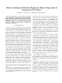
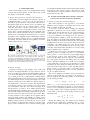
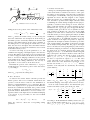
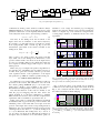
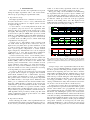
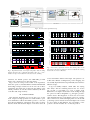
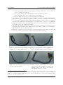
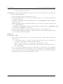
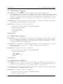
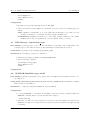
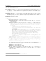
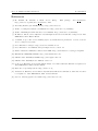
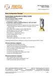
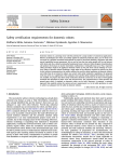
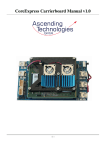
Control Engineering Andreas Rüesch MSc report Supervisors: Prof.dr.ir. S. Stramigioli Dr. R. Carloni MSc A.Y. Mersha August 2011 Report nr. 014CE2011 Control Engineering EE-Math-CS University of Twente P.O.Box 217 7500 AE Enschede The Netherlands Kinetic Scrolling-based Position Mapping for Haptic Teleoperation of Unmanned Aerial Vehicles A. Rüesch∗ , A. Y. Mersha∗∗ , S. Stramigioli∗∗ and R. Carloni∗∗ Abstract— In this paper, we present a haptic teleoperation control algorithm for unmanned aerial vehicles, applying a kinetic scrolling-based position mapping. The proposed algorithm, disposes of high precision for small and fine operations. Additionally, it allows to overcome large distances in the unbounded workspace of the aerial vehicle in a fast and intuitive manner. For validation purposes, results of simulations and experiments are presented. I. INTRODUCTION The remote control of unmanned aerial vehicles (UAV) represents a challenging task, which in general requires a lot of experience and an excellent instinct by the pilot. Thus, in the recent past a lot of research has been conducted and progress in developing autonomous UAVs has been made by different parties for various applications and different vehicle configurations, e.g. [1]–[5]. Nevertheless, there still are applications where a fully autonomous behaviour is not possible or desirable, namely in tasks like e.g. air surveillance, search and rescue missions or inspection tasks, which still require human reasoning or supervision to be successfully accomplished. As in the scope of the European project AIRobots [6], within which this work was accomplished, the main objective is to develop an aerial inspection robot, that interacts with its surrounding under the supervision of a human operator. While the operator stays in the control loop and is responsible for the high level tasks, he should not be concerned with low level control such as the stabilization of the avionic system itself. The UAV should act like a “flying hand” [6], which is guided by the operator through an interface as natural and intuitive as possible to accomplish high level interaction tasks with the environment. In the field of semi-autonomous robotics, haptic teleoperation has proved its great potential and benefit of providing major environmental awareness to a human operator while enabling high control accuracy, specially in the field of surgical robotics [7] or traditional robotic manipulators [8]. Consequently, several research groups recently started to investigate the application of haptic teleoperation to aerial vehicles. Lam et al. [9]–[11] present a theoretical and experimental investigation of the use of wave variables for a This work has been funded by the European Commission’s Seventh Framework Programme as part of the project AIRobots under grant no. 248669. *A. Rüesch is with the Autonomous Systems Lab, Eidgenössische Technische Hochschule Zürich, Switzerland. Email: [email protected] **A. Y. Mersha, S. Stramigioli and R. Carloni are with the Faculty of Electrical Engineering, Mathematics and Computer Science, University of Twente, The Netherlands. Email: {a.y.mersha, s.stramigioli, r.carloni}@utwente.nl collision-avoidance system for UAVs. The feedback force is calculated based on an artificial force-field. Schill, Mahony et al. [12], [13] propose the use of an admittance control framework for haptic teleoperation of UAVs, furthermore, the concept of optical impedance to provide a haptic feedback for obstacle avoidance is introduced. Besides simulation results also an additional experiment of controlling the altitude of a real quadrotor is presented. Stramigioli et al. [14] present an approach, which is based on an energy consideration and makes use of the concepts of network theory and portHamiltonian systems, to provide the human operator with a sensitive cognition of the environment. Lee et al. [15] introduce a haptic teleoperation framework to control multiple UAVs over the internet, semi-experimental results are presented for validation purposes. To control the UAV’s position, the aerial vehicle is usually equipped with an on-board position or velocity controller. Accordingly, the input consists of a corresponding reference and a desired heading angle. In classical haptic teleoperation, where the haptic device is typically a replica of the slave device, and thus disposes similar kinematics, a direct mapping of the master’s position to the slave’s is common. Caused by the dissimilarities of the kinematics of an aerial vehicle and of a hapitc device, an alike direct mapping is usually not feasible. Moreover, the workspace of a hapitc device is limited and quite small compared to the UAV’s, which is essentially infinite and unbounded. In order to overcome these limitations, the commonly used approach in literature, e.g. [10], [15], [16], is to map the displacement of the haptic device to a reference velocity of the UAV. This mapping method causes a trade off in the precision and the ease of use of the haptic teleoperation. The contribution of this paper is a new approach to overcome the limitations of the workspace of the haptic device. The approach is inspired and based on kinetic scrolling. For validation purposes simulation and experimental results are presented. The paper is organized as follows. In Sec. II, some preliminary information about haptic teleoperation applied to UAVs and about kinetic scrolling is given. In Sec. III the proposed haptic teleoperation algorithm is introduced, including the kinetic scrolling-based position mapping, the proposed force feedback and some consideration about its stability. The simulation results are shown in Sec. IV. In Sec. V the results of the flight experiments with a real UAV are presented. Conclusions and future work are discussed in Sec. VI. II. PRELIMINARIES This section briefly presents some background knowledge of haptic teleoperation applied on UAV, followed by a brief introduction of the kinetic scrolling. A. Haptic Teleoperation for Unmanned Aerial Vehicles The scheme of a typical haptic teleoperation control loop is illustrated in Fig. 1. As can be seen, the interaction of the human operator with the aerial vehicle (slave device), through the haptic device (master device), is bilateral. The master and the slave side are equipped with a separate controller: the master controller’s main tasks are to map the user’s inputs to the corresponding reference of the slave device, and to compute and display the force feedback on the master device. On the other side, the slave controller ensures that the slave is following the desired trajectory or velocity, depending on the configuration. The communication channel, between the master and slave device, is typically unreliable and usually introduces unknown and probably even timevarying delays into the control loop. Master Side Slave Side FH FF FS FF Human Operator Aerial Vehicle Haptic Interface xm Master Controller x∗s xs Communication Channel xs x∗s xs FE ui Environment Slave Controller Fig. 1: Scheme of a haptic teleoperation control loop. Where xm represents the position of the haptic device, x∗s the reference position of the UAV, xs its actual position. Furthermore, the applied force by the human operator is denoted with FH , the feedback force with FF , the interaction forces of the UAV with the environment are represented with FS and FE , and the input commands of the slave controller are denoted with ui . B. Kinetic Scrolling Computer technology and graphics have dealt with workspace and display limitation for ages, therefore various forms of scrolling are common and well established methods to overcome this limitation. On devices with a touchscreen, e.g. on smart phones, the so-called kinetic scrolling method became standard in the recent past. The user is provided with two different input modes, as long as his finger is in contact with the touchscreen, its movements are directly mapped to the displacement of the screen contents. The displacement of the screen contents, i.e. the scrolling, does not necessarily stop immediately, when the user releases his finger from the input device, it is able to move further and decelerates automatically till it eventually comes to a complete stop. The amount of this additional scrolling is defined by the speed of the user’s motion just before he releases the contact. Thus, for large distances a fast scrolling can be applied without losing the high accuracy and usability for small, precise manipulations. Kinetic scrolling is in literature also known as flicking, releated work can be found in [17], [18]. As stated above, kinetic scrolling became standard on modern smart phones, where it allows the user to interact with his gadget in a natural and intuitive manner. This inspired and motivated the mapping of the operator’s inputs to the reference signal of the slave device of the teleoperation control loop proposed and described in Sec. III. III. HAPTIC TELEOPERATION WITH A KINETIC SCROLLING-BASED POSITION MAPPING A. Kinetic Scrolling-based Position Mapping This section describes a new approach to overcome the limitation of the workspace on the master side, based on the kinetic scrolling described in Sec. II-B. 1) Core Idea: Like the kinetic scrolling, the mapping algorithm is divided into two modes, namely a direct and a sliding mode. For the direct mode, a proportional mapping of the master’s position to the slave’s reference position is proposed. Whereas in the sliding mode, the operator is provided with the possibility to “slide” the reference position away, the sliding is decelerated automatically similar to the kinetic scrolling on smart phones. The amount of the sliding is influenced by the user’s speed in the direct mode before switching to the sliding mode. Note that, in both modes a reference position is transmitted to the on-board position controller of the aerial vehicle, thus there is no need to switch between different slave controllers. 2) Mathematical Description: To realize the sliding of the reference position, a virtual point mass mv is introduced, whose position xv is in both modes proportionally mapped to the reference position of the aerial vehicle x∗s . For the direct mode the master device is coupled to the virtual mass by a stiff spring, whereas in the sliding mode, the virtual mass is uncoupled. Furthermore, a virtual viscous damping of the virtual mass is introduced as an external force, which decelerates the mass during the sliding mode. The operator is provided with a full control over the switching between the two modes, e.g. through a button on the haptic device. In Fig. 2 the physical model of the core idea is illustrated for the one dimensional case. The viscous damping is modeled to be proportional to the velocity of the virtual mass. According to the principle of linear momentum, the following equation of motion holds for the virtual point-mass: mv ẍv = −k(λ)(xv − xm ) − dẋv , (1) where xm , xv ∈ R3 represent the positions of the master device and the virtual mass respectively, mv denotes its mass, d acts as a viscous damping coefficient, and k(λ) stands for the spring constant of the coupling, depending on the state of the switch λ. Note that, for the spring constant k(λ) the following holds: kc if λ = 1 k(λ) = (2) 0 if λ = 0 During the sliding phase the virtual viscous damping ensures that, the virtual mass eventually comes to a stop. It can be easily verified from Eq. (1) and (2), that in the xm xv kc C. Stability Consideration λ mv d µ=0 Fig. 2: Illustration of the core idea (1D) sliding mode for the position of the virtual mass holds: xv (t) = v0 ˜ (1 − e−dt ), ˜ d d with d˜ = , mv (3) where v0 denotes the initial velocity, i.e. the velocity just before the virtual mass was decoupled. As shown in Eq. (3) the human operator can directly influence the direction and amount of the sliding with his motion before switching to the sliding mode, i.e. decoupling the virtual mass, i.e. the faster the user moves the haptic device the further will the virtual mass slide, in contrary the virtual mass does not slide if the initial velocity is zero. As can be seen in Eq. (1)-(3) the parameters kc , mv and d influence the mapping of the haptic inputs to the reference position. The stiffness of the spring kc has to be high enough to ensure a high performance in the direct mode. Since the mass mv and viscous damping coefficient d are also present in the sliding mode, they can be used to tune the sensitivity and amount of the sliding, furthermore, the viscosity is responsible to avoid overshoots in the direct mode. Eventually the position of the virtual mass xv is proportionally mapped to the reference position of the slave device x∗s , according to x∗s = KpM xv , (4) B. Force Feedback As stated in Sec. II the master controller provides the human operator with a force feedback, which allows the operator to feel the slave’s reaction to his stimulations as well as to external disturbances, e.g. to wind gusts. The first term of the displayed force is proportional to the difference between the commanded and actual slave position, which gives an indication of the magnitude and direction of the positional deviation. Furthermore, to avoid too harsh or too rapid movements of the haptic device an additional damping of its velocity is proposed. Thus, for the force feedback vector holds: 0 0 −m 1 0 0 0 0 kc mv 0 0 0 0 −m " where KpM represents the scaling factor. FF = −KpF (x∗s − xs ) − KdF ẋm , During any telemanipulated flight maneuver, the stability of the aerial vehicle is crucial for the success of the operation. Hence, in the following some important consideration concerning the overall stability of the proposed teleoperation algorithm are shown. The flow diagram of the complete haptic teleoperation loop is illustrated in Fig. 3. As can be seen, the UAV is provided with a flight controller, which is stabilizing the vehicle during its flight. For this purpose, typically, a cascaded control strategy is chosen, where the UAV’s rotational dynamics are treated separately from its translational ones, e.g. [2], [5], [19]. An approach like this, is usually feasible, given the two sets of dynamics are timescale separated. As Pound et al. [19] show, the free flight stability for an UAV can be ensured by two cascaded PD controllers and be proven by applying the analysis by Bullo and Murray for stabilizing a rigid body with PD control [20]. As depict in Fig. 3, an additional cascaded loop for the master controller of the haptic teleoperation is employed, again under the assumption, that the cascaded loops are timescale separated. Hence, the stability of the master controller can be analysed independently. For this purpose the haptic device is modeled as a mass-spring-damper system, whereas the intrinsic damping is assumed to be marginal. Primarily, the direct mode is considered, therefore the switch of the mapping is closed (λ = 1). As illustrated in the flow diagram (Fig. 3) the inputs to the master controller consist of the force applied by the operator FH and the position of the slave T device xs , i.e. u = [ FH xs ] , the desired reference of ∗ the slave xs represents its output, i.e. y = x∗s . The states of the subsystem are the positions and velocities of the master device and of the virtual mass respectively, i.e. for T the state vector holds: x = [ ẋm xm ẋv xv ] . Thus the dynamics of the subsystem are described by the following system matrices: Kp k̃ δ 1 A B c d # = h where KpF and KdF denote the corresponding scaling parameters. mh 0 0 kc −m 0 0 1 0 0 0 0 KpM 0 0 − md v v , (6) with k̃ = KpM KpF and δ = KdF + dh , where dh represents the internal damping of the haptic device and mh its mass. It can be easily verified, that for the characteristic polynomial of the linear system, given in Eq. (6), holds: det(sI − A) = s4 + |{z} a4 =1 d δ kc d δ + s3 + + s2 mv mh mv mv mh | {z } | {z } =a3 =a2 kc δ kc k̃ + s+ . mv mh mv mh | {z } | {z } =a1 (5) F mh h =a0 (7) According to the Routh-Hurwitz stability criterion, the system is asymptotically stable iff a0...4 > 0, a3 a2 > a4 a1 and a3 a2 a1 > a4 a21 + a23 a0 . Since all spring and damping FH λ xm Haptic Dev − kc − 1 mv ẍv R ẋv R xv x∗s KpM − Pos Ctrl Att Ctrl ui UAV xs FF − KdF ẋm d − KpF Fig. 3: Complete haptic teleoperation loop Since δ and mh are stricly positive, the master controller stays stable, also in the sliding mode. Furthermore, if the operator switches back to the direct mode, the haptic device is seen to be virtually shifted to the virtual mass. Thus the user’s inputs are directly mapped with respect to the new initial position. Hence, the proposed haptic teleoperation algorithm does not introduce any instabilities into the flight control loop in either mode, given the cascaded control loops are timescale separated and the control parameters of the haptic teleoperation loop fulfill the condition specified in Eq. (8). IV. SIMULATION RESULTS To validate the proposed algorithm, simulation results are presented in this section. The simulations were run with the software package MATLAB [21], to record the user’s inputs and to display a force feedback to the operator a ForceDimension Omega6 haptic device [22] was used. Note that the intention of this section is mainly to validate the proposed mapping, thus the slave device was simply modeled as a point mass, furthermore a standard PID controller was used as a slave controller. Comprehensive experiments with a real UAV are presented in Sec. V. In Fig. 4 the results of a simple 1D simulation experiment are illustrated. The top plot shows the position reference and simulated position of the UAV. The second plot shows the position of the haptic device in the corresponding direction, furthermore, the force feedback and in the lowerst plot the switching between the direct (λ = 1) and the sliding mode (λ = 0) are illustrated. The scaling factor KpM was set to one. As can be seen in the plots, although the workspace of the haptic device is limited to 0.2m, the human operator is altiude [m] 1.4 pos virt mass (x v) 1.2 pos UAV (xs) 1 0.8 0.6 0.4 0.2 haptic position [m] 25 30 35 time [sec] 40 45 30 35 time [sec] 40 45 30 35 time [sec] 40 45 30 35 time [sec] 40 45 0.1 0 −0.1 pos haptic z 25 force feedback Note that, in the sliding mode the movement of the haptic device has no influence on the desired trajectory. It is trivial to see that this trajectory generation is in this mode asymptotically stable, consider e.g. Eq. (3). For the characteristic polynomial of the master controller in the sliding mode, holds: δ , (9) det(sI − A) = s s + mh force z 0.5 0 −0.5 25 state of switch [−] (8) 1 0.5 0 state 25 Fig. 4: Simulation results of the haptic teleoperation with the kinetic scrolling-based position mapping. Note, vertical, dashed lines in the top three plots indicate the switching between the two modes Fig. 5 shows the effect of the virtual viscous damping coefficient, for the same haptic inputs. The result, shown in Fig. 4, was overlayed with the results of simulations with the doubled and halved virtual damping. 2 altiude [m] a3 a2 a1 > a4 a21 + a23 a0 still able to cover a large aera with the proposed mapping method. Note that, the sliding can be aborted, bringing the UAV to a complete stop, or be extended to a larger motion, covering larger distances, as illustrated at the end of the experiment. SIM1: pos virt mass (xv) 1.8 SIM1: pos UAV (xs) 1.6 SIM2: pos virt mass (xv) 1.4 SIM2: pos UAV (xs) 1.2 SIM3: pos virt mass (xv) 1 SIM3: pos UAV (xs) 0.8 0.6 0.4 25 30 35 time [sec] 40 45 Fig. 5: Simulation SIM1: force z results of the haptic teleoperation with the kinetic 1 SIM2: force z scrolling-based position mapping for different damping coefficients (SIM1: SIM3: force z d1 =0.5d, SIM2: d2 = 2d, SIM3: d3 = d/2); virtical, dashed lines indicate the switching 0 force feedback [N] coefficients are strictly positive, the first condition is always fulfilled. Furthermore, it can be shown that any choice of the parameters satisfies the second inequality. Thus the stability of the subsystem boils down to the following condition: −0.5 25 30 35 time [sec] 40 45 The flight experiments were conducted in an indoor test area (size about 4.00m × 3.75m × 2.75m), which meets the necessary safety precautions. A complete system overview is depicted in Fig. 6. 1) Aerial Vehicle: As an aerial platform the AscTec Pelican quadrotor [23] was used for the experiments. This quadrotor disposes of a high payload capacity (up to 500g) and agility. The helicopter is provided with all essential on-board sensors plus two ARM7 micro processors, which build the so-called Flight Control Unit (FCU). Furthermore it is equipped with an additional processor board, based on an Intel Atom 1.6 GHz processor, which entails high computational on-board power. 2) Haptic Device: The human operator interacts with the aerial vehicle through the Force Dimension Omega.6 haptic device [22]. This device provides translation as well as rotation sensing with high accuracy, and it is featured with a precise gravity compensation to enable accurate hapitc transparency. Translational forces can be displayed continuously up to 12N . The provided Force Dimension SDK [22] is used as a software interface to the device. 3) External Positioning System: As an external positioning system a PTI PhoeniX VisualEyez VZ 4000 tracker unit is used [24]. The tracker captures the motion of the active markers (LED), which are mounted on the Pelican. The absolute position measurements of those markers are used for the estimation of the UAV’s pose. Since the VisualEyez VZSoft does not provide an estimation of the pose of a rigid body, this estimation is run on the ground station, according to the algorithm proposed by Challis in [25]. 4) Software: Both, the on-board atom processor board and the ground station computer are equipped with a Ubuntu Linux 10.10, furthermore the so-called Robot Operating System (ROS) [26] framework is used as a middleware. The ground station executes the teleoperation algorithm and a ROS interface to the haptic device. Furthermore the UAV’s pose is estimated from the measured marker data. On-board, a ROS interface is running on the Atom board, additionaly the position and attitude controller of the UAV are executed on the FCU. As a position controller a simple PID controller with a feedthrough term is used, as proposed and provided by [5], [27], the attitude controller is based on a PD algorithm, and is provided by AscTec [23]. The aerial vehicle communicates with the ground station over a WiFi data link (802.11n standard). B. Experimental Results In the following, the results of the experimental tests are presented. In the first part the set-up described above (Sec. VA) was used to perform the experiments. Additionally, some postition (z−dir) [m] A. Experimental Set-up pos ref pos UAV 0.9 0.8 0.7 0.6 0.5 85 90 95 100 105 110 100 105 110 100 105 110 time [sec] force feedback (z−dir) [N] This section first describes the experimental set-up used during the flight experiments with a real aerial vehicle, followed up by presenting the experimental results. results of an inter-country experiment, where the operator and aerial vehicle were locally separated, are shown. The top plot of Fig. 7 shows the altitude of the UAV during the experiment, where the operator’s input is similar to the one used during the simulation presented in Sec. IV. The operator first commands the UAV in the direct mode, before he slides the vehicle up, at the end of the plot, again the extension of the sliding can be seen. The displayed force feedback and the switching between the two different modes are shown in the two lower plots of Fig. 7. 4 force feedback 2 0 −2 −4 85 90 95 time [sec] state of switch [−] V. EXPERIMENTS 1 0.5 0 button 85 90 95 time [sec] Fig. 7: Experimental results of the haptic teleoperation with the kinetic scrolling-based position mapping. Top: commanded and actual altitude; middle: force feedback in z-direction; bottom: switching between the two operation modes A larger excerpt of the experimental results in all directions (x, y, and z) is illustrated in Fig. 8. As can be seen, after the direct operation and sliding slowly in (almost only) one direction at the beginning, the user is also able to slide the UAV rapidly in multiple direction simultaneously, as shown at the end of the experiment. Note that, the heading of the UAV was kept constant during the whole flight. The plots show that the mapping works fine, even in the presents of an average performance of the position control and with varying communication delays. The transition between the two modes is smooth and results in a sleek trajectory. As stated above, besides the local experiments an additional experiment was performed, where the human operator and the aerial vehicle were geographically far separated and communicated through a standard internet connection. The master side, including the operator, were located at the University of Twente/Netherlands, whereas the UAV and its controller were flying at the ETH Zürich/Switzerland. During this experiment a different quadrotor was used, it is equipped likewise with a FCU provided by AscTec [23], the airframe and position controller are developed by the ASL [28]– [30] though. Furthermore, a Vicon-System [31] was used as an external positioning system. For a better environmental Ground Station On-board Flight Ctrl Unit xm xv k Ref FF Haptic Interface Ctrl Inputs Data Exchange UAV Data 802.11n Pos Ctrl λ m d µ=0 Com Haptic Teleop w Kinetic Scrolling Com Att Ctrl UAV Pose Pose Estimation Marker x̂ = (x̂, ŷ, ẑ, ϕ̂, θ̂, ψ̂) Data UAV Atom Board LED Markers 3DTracker System Human Operator 0.2 0.1 0 pos ref −0.1 120 130 0.1 100 110 120 130 time [sec] 140 150 160 100 110 120 130 time [sec] 140 150 160 0 pos ref pos UAV −0.4 90 100 110 time [sec] 120 130 140 1 pos ref pos UAV 0.8 0.6 postition (z−dir) [m] pos UAV −0.1 pos ref pos UAV 1.5 1 0.5 100 90 100 110 time [sec] 120 130 140 5 110 120 force x 100 110 time [sec] 120 130 1 force y 140 force z button 0.5 0 90 100 110 time [sec] 120 130 140 Fig. 8: Experimental results of the haptic teleoperation with the sliding mapping. Top three plots: commanded and actual position in x, y, and z direction; 4th plot: force feedback in z-direction; bottom: switching awareness, the human operator was additionally provided with a video stream from an off-board camera . Fig. 9 shows an excerpt of the results of the experiment, where the operator controlled all three translational DOF and the heading was kept constant. As can be seen, also in these experiments the trajectories produced by the sliding of the virtual point-mass are smooth, and are tracked by the slave controller with a high accuracy. VI. CONCLUSIONS The mapping algorithm, proposed in the scope of this work, disposes of high precision for small and fine operations, furthermore it allows the human operator to overcome the workspace limitation of the haptic device and cover large distances in the unbounded workspace of the slave device in 140 150 160 170 force x force y force z 0 −2 100 90 130 time [sec] 2 110 120 0 −5 170 2 0.4 0.2 170 −0.2 pos ref 0 postition (z−dir) [m] −0.5 140 postition (y−dir) [m] 110 time [sec] pos ref pos UAV 0 force feedback [N] postition (y−dir) [m] 100 0.2 force feedback [N] 0.5 pos UAV 90 state of switch [−] postition (x−dir) [m] 0.3 state of switch [−] postition (x−dir) [m] Fig. 6: Overview of the experimental set-up 130 time [sec] 140 150 160 1 170 button 0.5 0 100 110 120 130 time [sec] 140 150 160 170 Fig. 9: Inter-country experiment: reference and current position of the slave device in all directions, furthermore the force feedback and switching between the two modes is illustrated. a fast and intuitive manner. The haptic teleoperation controller with a kinetic scrolling-based position mapping was successfully implemented and experimentally tested with two different set-ups. A rigorous stability analysis, which takes the varying time delays and the switching between the two modes into account, is conceivable as a topic of future work. Furthermore, an adaptive deceleration of the sliding through the operator would be imaginable, e.g. through a pressuresensitive device. The integration of vision sensors for better environmental awareness of the human operator is considerable, as well as tests, without the high precision of an external positioning system, instead vision based flight control could be used, which would influence the performance of the position controller and thus also of the teleoperation. VII. ACKNOWLEDGMENT Sincere thanks are expressed to Micheal Burri, Janosch Nikolic and Christoph Hürzeler of the Autonomous Systems Lab of ETH Zürich for their support and the realisation of the inter-country experiment. R EFERENCES [1] G. Hoffmann, D. Rajnarayan, S. Waslander, D. Dostal, J. Jang, and C. Tomlin, “The stanford testbed of autonomous rotorcraft for multi agent control (starmac),” in Digital Avionics Systems Conference, The 23rd, vol. 2, pp. 12–E, IEEE, 2004. [2] S. Bouabdallah and R. Siegwart, “Backstepping and sliding-mode techniques applied to an indoor micro quadrotor,” in Robotics and Automation, 2005. ICRA 2005. Proceedings of the 2005 IEEE International Conference on, pp. 2247–2252, IEEE, 2005. [3] S. Lupashin, A. Schollig, M. Sherback, and R. D’Andrea, “A simple learning strategy for high-speed quadrocopter multi-flips,” in Robotics and Automation, IEEE International Conference on, pp. 1642–1648, IEEE, 2010. [4] N. Michael, D. Mellinger, Q. Lindsey, and V. Kumar, “The grasp multiple micro-uav testbed,” Robotics & Automation Magazine, IEEE, vol. 17, no. 3, pp. 56–65, 2010. [5] M. Achtelik, M. Achtelik, S. Weiss, and R. Siegwart, “Onboard imu and monocular vision based control for mavs in unknown in- and outdoor environments,” in Proc. of the IEEE International Conference on Robotics and Automation, 2011. [6] Innovative Aerial Service Robots for Remote Inspection by Contact (AIRobots). http://www.airobots.eu. [7] Intuitive Surgical, “The da Vinci Surgical System.” http://www.intuitivesurgical.com. [8] W. Chou and J. Xiao, “Haptic teleoperation of robotic manipulator,” Robotic welding, intelligence and automation, pp. 51–59, 2007. [9] T. Lam, M. Mulder, and M. Van Paassen, “Haptic Feedback for UAV Tele-operation-Force offset and spring load modification,” in Systems, Man and Cybernetics, IEEE International Conference on, vol. 2, pp. 1618–1623, IEEE, 2006. [10] T. Lam, M. Mulder, and M. Van Paassen, “Haptic feedback in uninhabited aerial vehicle teleoperation with time delay,” Journal of Guidance, Control, and Dynamics, vol. 31, no. 6, pp. 1728–1739, 2008. [11] T. Lam, H. Boschloo, M. Mulder, and M. Van Paassen, “Artificial force field for haptic feedback in UAV teleoperation,” Systems, Man and Cybernetics, Part A: Systems and Humans, IEEE Transactions on, vol. 39, no. 6, pp. 1316–1330, 2009. [12] F. Schill, X. Hou, and R. Mahony, “Admittance mode framework for haptic teleoperation of hovering vehicles with unlimited workspace,” in Australasian Conference on Robotics Automation, 2010. [13] R. Mahony, F. Schill, P. Corke, and Y. Oh, “A new framework for force feedback teleoperation of robotic vehicles based on optical flow,” in Robotics and Automation, IEEE International Conference on, pp. 1079–1085, IEEE, 2009. [14] S. Stramigioli, R. Mahony, and P. Corke, “A novel approach to haptic tele-operation of aerial robot vehicles,” in Robotics and Automation, IEEE International Conference on, pp. 5302–5308, IEEE, 2010. [15] D. Lee, A. Franchi, P. Giordano, H. Son, and H. Bülthoff, “Haptic Teleoperation of Multiple Unmanned Aerial Vehicles over the Internet,” in IEEE Int. Conf. on Robotics and Automation, 2011. [16] H. Rifaı̈, M. Duc Hua, T. Hamel, and P. Morin, “Haptic-based bilateral teleoperation of underactuated Unmanned Aerial Vehicles,” in IFAC World Congress, 2011. [17] A. Reetz, C. Gutwin, T. Stach, M. Nacenta, and S. Subramanian, “Superflick: a natural and efficient technique for long-distance object placement on digital tables,” in Proceedings of Graphics interface 2006, pp. 163–170, Canadian Information Processing Society, 2006. [18] M. Baglioni, S. Malacria, E. Lecolinet, and Y. Guiard, “Flick-andbrake: finger control over inertial/sustained scroll motion,” in Proceedings of the 2011 annual conference extended abstracts on Human factors in computing systems, pp. 2281–2286, ACM, 2011. [19] P. Pounds and A. Dollar, “Uav rotorcraft in compliant contact: Stability analysis and simulation,” in International Conference on Intelligent Robots and Systems, 2011. [20] F. Bullo and R. Murray, “Proportional derivative (pd) control on the euclidean group,” in European Control Conference, 1995. [21] [22] [23] [24] [25] [26] [27] [28] [29] [30] [31] MathWorks, “MATLAB/Simulink.” http://www.mathworks.com/. Force Dimension, “Omega.6.” http://www.forcedimension.com. Ascending Technologies GmbH (AscTec). http://www.asctec.de. PTI PhoeniX, “VisualEyez VZ4000.” http://www.ptiphoenix.com. J. Challis, “A procedure for determining rigid body transformation parameters,” Journal of Biomechanics, vol. 28, no. 6, pp. 733–737, 1995. ROS, “Robot Operating System.” http://www.ros.org. M. Achtelik, M. Achtelik, S. Weiss, and L. Kneip, “ROS package: asctec hl interface.” http://www.ros.org/wiki/asctec hl interface, 2011. C. Roos, C. Hüerzeler, and S. Bouabdallah, “Design of a CollisionTolerant Airframe for Quadrotors.” ASL, ETH Zurich, 2009. Internal Report. A. Rüesch, C. Hüerzeler, and J. Nikolic, “Dynamicas Identification & Validation, and Position Control for a Quadrotor.” ASL, ETH Zurich, 2010. Internal Report. M. Burri, J. Nikolic, and C. Hüerzeler, “Robust Flight Controller for Aerial Indoor Inspections.” ASL, ETH Zurich, 2011. Internal Report. Vicon, “Motion Capture Systems.” http://www.vicon.com. Documentation Abeje Y. Mersha and Rüesch Andreas Appendix/Documentation Contents 1 Brief Introduction 1.1 Safety Instructions . . . . . . . . . . . . 1.2 Prerequisites . . . . . . . . . . . . . . . 1.2.1 Safety Pilot . . . . . . . . . . . . 1.2.2 Robot Operating System (ROS) 1.3 Versions of used Software Packages . . . 1.4 Versioning . . . . . . . . . . . . . . . . . . . . . . . . . . . . . . . . . . . . . . . . . . . . . . . . . . . . . . . . . . . . . . . . . . . . . . . . . . . . . . . . . . . . . . . . . . . . . . . . . . . . . . . . . . . . . . . . . . . . . . . . . . . . . . . . . . . . . . . . . . . . . . . . . . . . . . . . . . . . . . . . . . . . . . . . . . . . . . . . . . . . . . . . . 2 2 2 2 2 2 2 2 Overview 2.1 Hardware Components . . . . . 2.1.1 Computers . . . . . . . 2.1.2 Peripherials . . . . . . . 2.2 Software Components . . . . . 2.2.1 ROS nodes . . . . . . . 2.2.2 Additional Executables 2.3 General Remarks . . . . . . . . . . . . . . . . . . . . . . . . . . . . . . . . . . . . . . . . . . . . . . . . . . . . . . . . . . . . . . . . . . . . . . . . . . . . . . . . . . . . . . . . . . . . . . . . . . . . . . . . . . . . . . . . . . . . . . . . . . . . . . . . . . . . . . . . . . . . . . . . . . . . . . . . . . . . . . . . . . . . . . . . . . . . . . . . . . . . . . . . . . . . . . . . . . . . . . . . . . . . . . . . . . . 4 4 4 5 5 5 6 6 3 Hardware 3.1 Force Dimension Omega6 . . . . . . . . 3.2 AscTec Pelican . . . . . . . . . . . . . . 3.2.1 Futaba Remote Control . . . . . 3.3 PTI Visualeyez VZ 4000 Tracker System . . . . . . . . . . . . . . . . . . . . . . . . . . . . . . . . . . . . . . . . . . . . . . . . . . . . . . . . . . . . . . . . . . . . . . . . . . . . . . . . . . . . . . . . . . . . . . . . . . . . . . . . . . . . . . . . 7 7 8 10 10 4 Software 4.1 ROS Package: air hapticteleop . 4.2 ROS Package: air logger . . . . . 4.3 ROS Package: omega6 . . . . . . 4.4 ROS Package: udpServer . . . . 4.5 ROS Message: hapticteleop msgs 4.6 MATLAB/Simulink target model 4.7 VZ GroundStation.exe . . . . . . . . . . . . . . . . . . . . . . . . . . . . . . . . . . . . . . . . . . . . . . . . . . . . . . . . . . . . . . . . . . . . . . . . . . . . . . . . . . . . . . . . . . . . . . . . . . . . . . . . . . . . . . . . . . . . . . . . . . . . . . . . . . . . . . . . . . . . . . . . . . . . . . . . . . . . . . . . . . . . . . . . . . . . . . . . . . . . . . . . . . . . . . . . . . . . . . . . . . 12 12 13 13 13 14 14 15 5 Tutorials 5.1 Procedures . . . . . . . . . . . . . . . . . . 5.1.1 Starting up the Tracking System . . 5.1.2 Starting up the Pelican . . . . . . . 5.1.3 Starting up the Haptic Teleoperation 5.2 Hints for Troubleshooting . . . . . . . . . . . . . . . . . . . . . . . . . . . . . . . . . . . . . . . . . . . . . . . . . . . . . . . . . . . . . . . . . . . . . . . . . . . . . . . . . . . . . . . . . . . . . . . . . . . . . . . . . . . . . . . . . . . . . . . . . . . . . . . . . . . . . . . . . . . . 16 16 16 16 18 18 A Appendix A.1 Code APIs . . . . . . . . . . . . . . . . . . A.2 Overview of SVN-Structure . . . . . . . . . A.3 Network Settings of WLAN of Flying Area A.4 Passwords . . . . . . . . . . . . . . . . . . . . . . . . . . . . . . . . . . . . . . . . . . . . . . . . . . . . . . . . . . . . . . . . . . . . . . . . . . . . . . . . . . . . . . . . . . . . . . . . . . . . . . . . . . . . . . . . . . . . . . . . . . . 19 19 19 20 20 August 26, 2011 . . . . . . . . . . . . . . . . . . . . . . . . . . . . . . . . . . . . . . . . . . . . . . . . . . . . . . . . 1 Abeje Y. Mersha and Rüesch Andreas 1 Documentation Brief Introduction This manual briefly describe the starting up procedures for haptic teleoperation of aerial vehicles using haptic intefaces (Omega6 and Phantom Omni) and AscTec Pelican miniature flying vehicle that have been in use in the Robotic and Mechatronic (RAM) Lab of the University of Twente. The procedures that are described here are far from being complete and comprehensive. Moreover, they are specific for our platform, flying environment and hardware and software architectures we used for our experiments. Besides of the operating instructions, the hardware and software components are described within this manual. 1.1 Safety Instructions Keep in mind, that the rotors of the quadrotor spin with a quite high speed, and due to a failure of any component the UAV (or part of it) can move rapidly in any direction. Thus, it is strongly recommended to perform flight test only within the flight area. Furthermore, the use of safety goggles and gloves is advised. 1.2 Prerequisites 1.2.1 Safety Pilot A safety pilot should always be present and know at least the basic commands to land and turn the UAV off, see chapter 3.4 of [4]. 1.2.2 Robot Operating System (ROS) The software components, presented in the following, are written in c++ and MATLAB/Simulink [10]. Furthermore, ROS [14] is used as a middleware, some basic knowledge is presupposed. It is highly recommended to at least complete the following tutorials of the ros-wiki1 : • Navigating the ROS filesystem (beginner level) • Creating a ROS package (beginner level) • Building a ROS package (beginner level) • Understanding ROS nodes (beginner level) • Understanding ROS topics (beginner level) • Using rxconsole and roslaunch (beginner level) • Running ROS across multiple machines (intermediate level) 1.3 Versions of used Software Packages Table 1 provides an overview of the versions of the used software packages and tools. 1.4 Versioning This manual describes the set-up including its software with reference to the revision #87 of the AIRobots SVN@UT, see also Appendix A.2. NOTE: the described set-up is currently at an early pre-release stage. USE AT YOUR OWN RISK! 1 ROS 2 Tutorials: http://www.ros.org/wiki/ROS/Tutorials August 26, 2011 Documentation Abeje Y. Mersha and Rüesch Andreas Software Tool/Package Version Robot Operation System (ROS) Diamondback 1.4.7 MATLAB/Simulink 7.11.0 (R2010b) Eclipse IDE for C/C++ Developers Helios Service Release 2 MS Visual Studio 2008 9.0.21022.8 RTM Table 1: Versions of used Software Tools/Packages August 26, 2011 3 Abeje Y. Mersha and Rüesch Andreas 2 Documentation Overview This section provides an overview of all used hard- and software components, illustrated in Fig. 1. Additionaly, a brief description of their functionalities and some important specifications are given. ROS MASTER /fcu/control serial link /asctec_hl_interface (UART 0 to HL 0) FCU /fcu/debug /udpServer UDP (local) /air_hapticteleop /teleop/kb_input /teleop/haptic_state /air_logger /omega6 Pose estimation groundstation.exe /teleop/haptic_state RS 232 VZSoft 802.11.n USB 2.0 Legend ROS core (master) ROS node ROS topic wired connection (serial, USB) UDP connection Figure 1: System overview of the aerial test set-up at UT 2.1 2.1.1 Hardware Components Computers Ground station (Laptop) Specifications: Linux Ubuntu 10.04 (32bit), Intel Quad Core Processor Main task: runs the master side of the teleoperation, furthermore the flight data is logged Tracker - Ground station (Desktop-PC) Specifications: WinXp (32bit), Intel Dual Core Processor Main task: runs the tracker interface (VZsoft) to record marker data, additionally the pose of the UAV is estimated and transmitted to the vehicle’s position controller Atom carrierboard (On-board) Specifications: Linux Ubuntu 10.10 (32bit), Intel Atom 1.6 GHz processor, brief manual provided by AscTec [3]. Main task: runs the interface to the flight control unit (FCU), thus the slave side of the teleoperation 4 August 26, 2011 Documentation 2.1.2 Abeje Y. Mersha and Rüesch Andreas Peripherials Haptic Device The Force Dimension Omega6 [7] was used for the experiments. The Omega6 provides translation as well as rotation sensing with high accuracy, furthermore it is featured with a precise gravity compensation to enable accurate hapitc transparency. Translational forces can be displayed continuously up to 12N . The set-up is though compatible for other haptic devices (only tested in semi-experiments for the Phantom Omni2 ) Aerial Vehicle As an aerial platform the AscTec Pelican quadrotor [2] was used for the experiments. This quadrotor disposes of a high payload capacity (up to 500g) and agility. The helicopter is provided with all essential on-board sensors plus two ARM7 micro processors, which build the the so-called Flight Control Unit (FCU), also called Autopilot in the manual of AscTec [4]. External Positioning System As an external positioning system a PTI PhoeniX VisualEyez VZ 4000 tracker unit is used [11]. The tracker captures the motion of the active markers (LED), which are mounted on the Pelican. The absolute position measurements of those markers are used for the estimation of the UAV’s pose. Router The Pelican communicates with the ground station through WiFi, the ground station and tracker ground station are connected with standard LAN cable to the router. A Sitecom wireless gigabit router 300N [16] was used. IMPORTANT NOTE: the 802.11n standard for the wireless data link is cruical for the success of the flight experiments! The network settings are provided in Appendix A.3. 2.2 2.2.1 Software Components ROS nodes air hapticteleop • Main task: runs combined with the MATLAB/Simulink Realtime-Workshop the master controller of the teleoperation. • Documentation: section 4.1. air logger • Main task: logs the flight data for offline analysis • Documentation: section 4.2. omega6 • Main task: provides an interface for ROS to the haptic device • Documentation: section 4.3. udpServer • Main task: server of th UDP bridge to the tracker ground station, puplishes the received estimation of the UAV’s pose within ROS. 2 Sensable Phantom Omni: for this haptic device is a corresponding ros package provided in the svn, see Appendix A.2, this package is based on the gt-ros-pkg of Georgia Tech (http://www.ros.org/wiki/gt-ros-pkg) and adjusted for the purposes of the described set-up August 26, 2011 5 Abeje Y. Mersha and Rüesch Andreas Documentation • Documentation: section 4.4. asctec hl interface • Main task: provides an interface for ROS to the FCU. • Documentation: puplished on the ROS wiki [1]. • Developed by Markus Achtelik, Michael Achtelik, Stephan Weiss, Laurent Kneip • Version: downloaded and installed on the 28/06/11 • Change log: – 28/06/11 - arue: changed default values in launch/fcu_parameters.yaml of state_estimation to HighLevel_SSDK and of position_control to HighLevel – 28/06/11 - arue: added launch of the \udpServer ROS-node to the fcu.lauch file 2.2.2 Additional Executables VZSoft • Main task: provides an interface to the tracker to record the markers’ position. • Documentation: VZ manual [12]. VZ GroundStation.exe • Main task: estimates the UAV’s pose from the markers’ measurments, and sends the estimation through UDP to the UAV. • Documentation: section 4.7. 2.3 General Remarks • Note: all coordinate systems are, if not explecitly denoted differently, according to the East-NorthUp (enu) convention3 . 3 according 6 to the ROS coordinate frame convention: http://www.ros.org/wiki/geometry/CoordinateFrameConventions August 26, 2011 Documentation 3 Abeje Y. Mersha and Rüesch Andreas Hardware In this section, all used devices are introduced. The links to manuals/documentation and hints to install the devices (might or also not be useful) are provided. 3.1 Force Dimension Omega6 Following description holds for the interaction of the device with a Linux Ubuntu 10.04/10 machine. brief intro Haptic device used for the teleoperation experiments. The Omega6 disposes of high accuracy in measuring the translational and rotational link doc the setup and installation is described in the provided user manual [8], documentation of the provided SDK can be found within its doc directory (open the index.html file with your favored web-browser) requirements before starting to install the Omega6, make sure: 1. you have the current Haptic SDK dhd-3.3.1.1556-linux-i686.tar.gz, file is provided on the Force Dimension USB drive or downloadable form the Force Dimension website 4 2. the GLUT (libglut3-dev) and USB programming library development files (libusb-1.0-0dev) have to be installed on your linux system sudo apt-get install libglut3-dev libusb-1.0-0-dev installation described in chapter 5 of the user manual [8] change log troubleshoot / hints • it is recommended to build the examples cd /dhd-3.3.1/examples make and run one of them to check if everything works fine, thus e.g type to run the gravity example: ./dhd-3.3.1/bin/gravity • Note that, you need to have write access on the corresponding usb port. For only giving the user a temporary write access, type the following command everytime you plug the device in: sudo chmod 666 [port_address] For a permanent change (i.e. if you don’t want to type the command above everytime), adjust the udev-default rules in the following manner: 1. sudo gedit /lib/udev/rules.d/50-udev-default.rules 2. change the MODE settings to 0666 in the following line: ... # libusb device nodes SUBSYSTEM=="usb", ENV{DEVTYPE}=="usb_device", MODE="0666" ... • Note that, USB 3.0 ports are (at least up until now) not supported by the Omega6 device. 4 link: http://www.forcedimension.com/download (registration required) August 26, 2011 7 Abeje Y. Mersha and Rüesch Andreas 3.2 Documentation AscTec Pelican brief intro an AscTec Pelican quadrotor was used as a miniature flying vehicle for the experiments. It is strongly recommended to read the manuals, provided by AscTec, thoroughly before starting up the robot. Some additional information to the platform are given in the following. link doc the Pelican including its FCU (aka Autopilot) are briefly described in [4], the atom carrierboard in [3]. The Futaba remote control (RC) is documented in [9]. requirements installation the Pelican is out of the box flyable with the RC, the procedure for autonomous resp. for haptic teleoperated flights is described in section 5. change log the default settings were adjusted in the following manner: 19/04/11 - arue installed Ubuntu 10.10 on the Atom’s MicroSD, according to CCNY wiki using the provided customized live CD: Ubuntu_10.10_AscTec.iso 5 → 20/04/11 - arue installed wicd, to access the eduroam WLAN the following steps are required (Note, this is only required to access the internet with the Pelican, e.g. for software updates, during the flight test a standalone network is used, which can be accessed without any special tricks): • • • • add file eap-ttls6 to \etc\wicd\encryption\templates sudo chmod 755 /etc/wicd/encryption/templates/eap-ttls echo eap-ttls | sudo tee -a /etc/wicd/encryption/templates/active in the wicd gui, set the following properties: – Identity: [email protected] – Path to CA Cert: /etc/ssl/certs/GTE_CyberTrust_Global_Root.pem – Anonymous Identity: [email protected] – Protocol: WPA – Encryption: TKIP – Password: your password 20/04/11 - arue installed ros diamondback (base installation) 28/06/11 - arue installed the ros package asctec_mav_framework [1] including the required HL firmware update. troubleshoot / hints • always turn the FCU on, if the Atom board is running. Otherwise there is no warning (beep sound) if battery voltage drops too low, can result in a permanent damage of the batteries. • it is possible to use an external power supply for the Pelican. The external power supply is though not powerful enough for actual flight maneuvers, but recommended if long “on-ground” task of the Atom are required, e.g. system updates . . . • if the monitor is connected to the Atom board, the graphical interface of Ubuntu can be started with startx. • if a rotor controller has to be exchanged, a reconfiguration of them is required, by following the procedure: 5 CCNY 6 can 8 wiki: http://robotics.ccny.cuny.edu/wiki/AscTec/Ubuntu be found in the svn, see also Appendix A.2 August 26, 2011 Documentation • • • • Abeje Y. Mersha and Rüesch Andreas 1. Connect the AscTec AutoPilot PC-Software 7 with the serial cable to the low level processor of the FCU (LL serial 0). 2. select corresponding port in the AutoPilot software and press “Connect”. 3. press down Shift, select Tools → Motor-Setup, release shift. 4. start the Motor Assignment Assistent and follow its instructions Follow the procedure described in [9] on p.18 (Link Procedure) to reconfigurate the RC transmitter with its receiver. This is necessary if you want to fly the Pelican with a different RC or e.g. if you had to send in the Pelican (since AscTec usually tests the set-up before sending it back, and maybe without mentioning that the reprogrammed the receiver to accomplish this!) AscTec provides three (undocumented) serial cables, see Fig. 2-4 for describtion. Furthermore, the AscTec USB module is illustrated in Fig. 5. Note that, the Pelican should never be powered up with demounted rotor blades (a motor controller was previously blown up while doing so). According to AscTec the reason might be that otherwise the motor controllers “choke”. Furthermore, starting problems of the FCU occurred through two bended pins of the HL serial 0 port, the bending caused a short circuit on the upper PCB of the FCU. Figure 2: Serial cable for connection between Figure 3: Bootload cable, used for firmware upthe Atom board and the FCU (usually: Atom date, more information would be published by UART port 0 <-> FCU HL serial 0) Asctec if such an update would be required. Figure 4: Bootload cable, probably as well just Figure 5: AscTec USB module, used for interneeded for system updates! action with the Asctec AutoPilot software, and firmware updates of the HL processor (usually: FCU HL/LL serial 0 <-> USB) 7 AutoPilot Software is downloadable form the customer download area of AscTec (http://www.asctec.de/83g53jT), it is recommended to install the AutoPilot software including the corresponding drivers for the AscTec USB module (illustrated in Fig. 5) on a windows computer. Instructions how to run it under Linux can be found in the CCNY wiki: http: //robotics.ccny.cuny.edu/wiki/AscTec/. August 26, 2011 9 Abeje Y. Mersha and Rüesch Andreas 3.2.1 Documentation Futaba Remote Control The remote control (RC) Futaba 7C-2.4GHz was as well purchased from AscTec. It is used in the default configuration, i.e. left stick up-down for collective thruth input, left stick left-right for yaw input; right stick up-down for pitching and to the left-right for rolling. Furthermore, two of the switches are used, namely the red marked switch on the left side, the so-called “GPS-Switch”, and the black marked switch on the right side, the so-called “Serial Interface Switch”. Note, all inputs are with respect to a body-fixed North-East-Down (NED) frame (direction of the x-axis is marked by an orange tag on the Pelican). Fig. 6 illustrates the RC with all switches and sticks in their default positions. For reconfiguration of the RC the reader is referred to the AscTec manual [4]. Figure 6: RC with all switches and sticks in their default positions, i.e. all switches “point away” from the operator, and the two sticks are in the zero position for roll, pitch, yaw and collective thrust. 3.3 PTI Visualeyez VZ 4000 Tracker System Following description holds for the interaction of the device with a WinXP machine. brief intro Motion capturing device for external position sensing of the UAV to provide the position controller with the necessary information about the current position of the UAV. link doc Visualeyez User Manual (ver. 3.6.0) [12] stored on the Visualeyez Software CD, hard copy available at CE. requirements the tracker system is stored in the following four boxes (for a detailed system contents list see page 14 of the user manual) • a shipping/carrying case, containing the motion tracking unit • two cardboard boxes, containing the required cables, adapters, markers • one small cardboard box, containing the software and dongle (license), the following 3 CDs are required for the installation: – Visualeyez Software CD – PTI Key Installation 10 August 26, 2011 Documentation Abeje Y. Mersha and Rüesch Andreas – Visualeyez Instructional Videos installation To set up the tracker system the following procedure is recommended: (see also chapter III of the user-manual, p42ff [12]) 1. check if all required parts are available (see above) 2. insert and install the driver of the provided PCI bus card (do not connect the tracker system to standard serial port) 3. run the license installation with the PTI Key Installation CD, AFTER the installation finished plug in the dongle 4. install VZSoft and whatever additional software you need from the Visualeyez Software CD (do not install VZlicense) 5. copy VZdriver.dll and VZdriverN.dll from the PTI Key installation CD to C:\WINDOWS\system32 (according to the README.txt on the CD) 6. set up the tracker system according to the instructional video Unpack and Set Up 7. start the VZSoft, the instructional video VZSoft And Capture provides further useful information about the tracking and capturing. change log troubleshoot / hints • the default coordinate system is not very handy, can though be easily changed by following the procedure: 1. recording a short take of 3 markers, one placed in the desired origin, second marker on the x-axis, and the thrid one some where in the xy plane 2. opening the System Settings → User Options → Coord Reference Frame 3. define coordinate reference frame with the With Current Take button and select the corresponding markers. • Note: in a couple experiments the VZSoft crashed when recording data for a long duration (about an hour). Thus, it is recommended to start recording just before the flight experiments. • Note2: up until now, only the wired capturing of data was possible. For some (for the author inexplicable) reasons the wireless markers did not work. August 26, 2011 11 Abeje Y. Mersha and Rüesch Andreas 4 Documentation Software This section describes the developed ros packages and VZ ground station software. The corresponding code APIs are provided in the subfolder \doc of the specific package, see also Appendix A.1. Furthermore the MATLAB/Simulink target model is briefly introduced. 4.1 ROS Package: air hapticteleop brief summary represents the core package for the haptic teleoperation with the described set-up. The user’s input are mapped to a desired reference position of the slave device, furthermore a corresponding force feedback is build and transmitted to the haptic device for displaying purposes. The package can be run in different configurations, which allow inter alia the prototyping of the teleoperation algorithms in MATLAB/Simulink RTW (see section 4.6). Furthermore, an emulation of the haptic device is provided for tracking of predefined trajectories. requirements the ros package requires the following packages to be installed: tf, roscpp, std_msgs, geometry_msgs, nav_msgs, hapticteleop_msgs and asctec_hl_comm. Furthermore, if run in the MATLAB/Simulink mode, the corresponding software package has to be installed. installation the following procedure is recommended: 1. make sure the package is within your ROS_PACKAGE_PATH 2. run the following command: roscd air_hapticteleop/ cmake CMakeList.txt rosmake configurations • currently three different modes are provided, all are derived from the base class HapticTeleop.cpp. To run the package in a desired mode, create an instance of the corresponding derived class (in the main.cpp file) Direct Mapping this mode allows a proportional mapping of the user’s input to the slave’s reference, where the force feedback is proportional to the deviation of the slave’s commanded and current position. The haptic teleoperation is only active as long as, the user presses the button on the end-effector of the haptic device. Sliding Mapping this mode contains an implementation of the kinetic scrolling-based mapping within c++. The user can switch between its two modes by pressing and releasing the button on the end-effector of the haptic device. Simulink Mode this mode is mainly used for the experiments, it builds a local UDP bridge to a MATLAB/Simulink RTW target, where the actual haptic teleoperation algorithm is running. Thus it allows a high usability and fast prototyping of algorithms. Note: a reference position is only send to the UAV if the “Force”-button of the haptic device is activated. • to emulate the haptic device, i.e. letting the UAV autonomously follow a predefined trajecetory an additional executable is provided (air_talker), the trajectory is defined in the emulatedHapticDev.cpp-file. • for the inter-country experiment with ETH Zurich different naming of couple topics is required, to do so enable the corresponding precompiler macro __EXP_ETH__ in the main header. Note: a model of their platform (slave incl. slave controllers) is provided in the ros package air_model, which can be used for preliminary tests/simulations and debug purposes. More detailed information to their set-up can be found in [13, 15, 5]. 12 August 26, 2011 Documentation 4.2 Abeje Y. Mersha and Rüesch Andreas ROS Package: air logger brief summary logs the flight data for offline analysis, namely the following ROS topics: /teleop/haptic_state, /teleop/force_feedback/, /fcu/control, /fcu/debug, /fcu/imu_custom/, /air_odometry. The topics are stored in separated text file in the current directory, thus it is recommended to change into the desired directory before starting this node. Furthermore, note that, new data is added at the end of the files, thus it is recommended to use different directories for different experiments. requirements the ros package requires the following packages to be installed: std_msgs, geometry_msgs, nav_msgs, hapticteleop_msgs and asctec_hl_comm installation the following procedure is recommended: 1. make sure the package is within your ROS_PACKAGE_PATH 2. run the following command: roscd air_logger/ cmake CMakeList.txt rosmake configurations - 4.3 ROS Package: omega6 brief summary provides an ROS interface for the interaction with the Force Dimension Omega.6 haptic device. It publishes the current state of the haptic device and displays a desired force feedback to the operator. This package makes use of the HapticSDK provided by Force Dimension. See [8] for a detailed documentation of the HapticSDK. requirements the Omega6 has to be installed on the machine, see section 3.1, furthermore, the package requires the following ros packages to be installed: std_msgs, geometry_msgs and hapticteleop_msgs installation the following procedure is recommended: 1. make sure the package is within your ROS_PACKAGE_PATH 2. run the following command: roscd omega6/ cmake CMakeList.txt rosmake configurations - 4.4 ROS Package: udpServer brief summary server of th UDP bridge between the tracker ground station and the aerial vehicle, it puplishes the received estimation of the UAV’s pose within ROS. A warning is puplished if the node does not receive a message form the ground station within a certain time period. requirements the package requires the following ros packages to be installed: std_msgs, geometry_msgs and nav_msgs, tf, roscpp and asctec_hl_comm installation the following procedure is recommended: 1. make sure the package is within your ROS_PACKAGE_PATH 2. run the following command: August 26, 2011 13 Abeje Y. Mersha and Rüesch Andreas Documentation roscd udpServer/ cmake CMakeList.txt rosmake configurations • the UDP port is specified through the macro UDP_PORT • besides the main executable pubTf two additional ones are provided for debuging purposes, namely: talker puplishes a “virtual-fake” pose of the UAV, without listening to the UDP port, it is strongly recomended to not use this executable during real flight tests. stateEstimation puplishes besides the pose of the UAV, a simple estimation of the UAV’s translational velocity, for bypassing the on-board estimator (Not yet tested). 4.5 ROS Message: hapticteleop msgs brief summary ros message type to store the state information of the haptic device. Furthermore, also a message type for the desired reference position including a heading angle is provided. requirements depending on the std_msgs and geometry_msgs installation the following procedure is recommended: 1. make sure the package is within your ROS_PACKAGE_PATH 2. run the following command: roscd hapticteleop_msgs/ cmake CMakeList.txt rosmake configurations - 4.6 MATLAB/Simulink target model brief summary runs the actual haptic teleoperation, if the air_hapticteleop package is in the corresponding mode. requirements MATLAB/Simulink including Realtime Workshop (RTW) installed. Furthermore, Eclipse Helios was used as an IDE-tool. installation to compile and build the Simulink model press CTRL+B configurations • to set-up MATLAB to use Eclipse as its IDE-tool run the following command within the MATLAB command window: (is only the frist time required) eclipseidesetup • make sure you have the Target Preferences-block set up proberly within your target-model. Furthermore a UDP receive and send block are required to interact with the air_hapticteleop ros-package 14 August 26, 2011 Documentation 4.7 Abeje Y. Mersha and Rüesch Andreas VZ GroundStation.exe brief summary since VZsoft does only provide position measurements for the LED markers, the pose of the UAV has to be estimated. This is done by applying the algorithm proposed by Challis et al. [6]. The executable makes use of the VZ SDK and publishes the estimation through a UDP bridge to any subscriber. requirements VZsoft has to be started and the corresponding markers have to be active, before the GroundStation.exe can be started. Futhermore, make sure all configuration files are available in the working directory, and the Armadillo C++ library8 is installed. installation no installation required. configurations • the following files are used to configure the software: udpSettings.ini ini-file for default UDP Settings (host IP, and UDP port), see below for temporary change. MarkerZeroConfig.txt contains the initial (zero) configuration of the LED markers with respect to the c.g. of the UAV. This file can be automatically generated by using the MATLAB script getZeroConfig.m found in the subfolder tools. To use the script, do the following: 1. mount the markers on the UAV (make sure they are fix) 2. align the UAV’s body frame with the fixed World frame (avoid any rotation or shift in xy-direction) 3. start capturing a data-set with the VZsoft. Note: at the beginning at least 4 markers should be visible. 4. take the UAV of the ground and start tilting and moving slowly, till you captured all markers at least once (in the presents of at least four other known markers) 5. export the take as a text-file from VZsoft (Motion Capture → Export Data). 6. run the MATLAB script getZeroConfig.m 7. dont forget to copy and paste the outputted file into the working directory of the GroundStation.exe CGZeroConfig.txt contains the educated guess of the c.g. in its initial (zero) configuration. BBFlightArea.txt bounding box of the flight area, used to neclect data of reflected markers. • for temporery changing the host IP address or the port of the UDP bridge, the program accepts command-line arguments, the following usage is recommanded: GroundStation.exe HostIP UdpPort two examples: (first one specifies only the host IP address, and uses the default UDP port, in the second one both values are changed) GroundStation.exe 192.168.0.117 GroundStation.exe 192.168.0.117 15712 • Note: the outputted pose estimation of the UAV is according to fixed World frame, whose origin is shifted to the initial zero position of the c.g., thus, if the UAV is on the ground, its z-component is zero! 8 Armadillo C++ linear algebra library http://arma.sourceforge.net/ August 26, 2011 15 Abeje Y. Mersha and Rüesch Andreas 5 Documentation Tutorials In the first part of this section, a tutorial over the required procedures to autonomously fly or haptic telemanipulate the Pelican is given. The second part provides some hints for troubleshooting. 5.1 Procedures It is assumed that all components described in section 2-4 are installed and work properly, otherwise the reader is kindly referred to the corresponding sections of this manual. The general procedure for the haptic teleoperated flight tests consists of the following steps: 1. starting up the tracking system 2. starting up the Pelican 3. starting up the Haptic Teleoperation 4. enjoy the noise and force feedback ;) Note: since the “life span” of the batteries is quite limited, it is recommended to prepare as much as possible before powering the Pelican up, i.e. terminals on the ground station can already be opened, and the corresponding command be written. Note2: keep in mind, that the Pelican should only be flown in the presents of a safety pilot, who is able to take over the control of the UAV in the case of any failure or emergency. 5.1.1 Starting up the Tracking System 1. Start up the VZ software of the tracking system on the Windows ground station by double clicking on the icon. 2. Click on the system setting and check if the units of measurement are set correctly in the user option. In the current setting it is in mm. 3. load up the coordinate frames by clicking on load button. Currently the file VZdata/coordSyst/crf_20110701_01.crf is used, for reconfiguration see 4.7. 4. Select the TCM8 mode by pressing on the button and select the markers in use. Currently, markers 1-5, 7-8 and 21-32 are in use. 5. Click on the record motion (green) button to start up the tracking system. At this point you should be able to see a flickering yellow light at the coordinates system approximately representing the pose of the pelican. You can even move the pelican around and observe the corresponding changes in the coordinates system on the VZ-soft. 6. Click on the pose estimation icon on the windows desktop and check up if the IP address on the tracking system is correct. The UAV’s IP is static and is currently set to 192.168.0.112. 5.1.2 Starting up the Pelican Remark: Make sure you to use gloves, put on goggles if are in the flying field and/or you want to move the pelican by hand while its powered up. 1. Switch on the Pelican’s FCU and Atom board. You should start the FCU on a level ground for calibrated startup of the gyros. When you switch on the FCU board, you must hear a beeping sound. It is highly recommended to read the manual [4] of the Pelican before starting up the pelican for the first time. 16 August 26, 2011 Documentation Abeje Y. Mersha and Rüesch Andreas 2. Startup a roscore from a ground station PC running ubuntu in which ROS is installed. Type the following command in the terminal roscore 3. Access the Atom board of the Pelican through the following command ssh asctec@asctec-atom 4. Type the following command on the terminal roslaunch asctec_hl_interface fcu.launch The above command starts up the asctec_hl_interface and the udpServer. 5. Do the sanity checks recommended in the tutorial of the ros package ros_asctec_hl_interface before running its trajectory tracking controller [1]. Note that the recommended check for the velocity an bias can only be done if the serial interface on the RC is switched on. The position sanity check can be done without it. 6. Switch off the serial port of the RC, if it is still switched on from the previous step. Make sure all switches on the RC are off and the sticks are on their default position. At this step, you are ready to fly the asctec Pelican. 7. Start up the motors of the Pelican by moving the yaw stick fully either to the right or to the left and releasing it as soon as the propellers start to rotate. All propellers of the pelican should be rotating at almost the same angular velocity as long as the pelican is not tilted. The thrust generated by the propellers is not enough to lift the UAV off. If you are interested in flying the Pelican from the RC, follow the steps suggested in the AscTec manual [4]. Proceed to the next step if you want to do autonomous flight or teleoperation. 8. To log data for offline analysis, change into a desired directory and run the air_logger, e.g. use the following command, mkdir FlightTest FlighTest/testMMDD FlightTest/testMMDD/testXX cd FlightTest/testMMDD/testXX rosrun air_logger air_logger 9. For way point tracking, activate the way point server client by typing, for further information of its usage see [1] rosrun asctec_hl_interface waypoint_server skip and proceed to the next step if you don’t need to do way point tracking. 10. For trajectory tracking, define your trajectory in the air_hapticteleop package with in the emulatedHaptic.cpp-file and compile and build the package. Type the following command to run this reference trajectory rosrun air_haptic_teleop air_talker skip and proceed to the next step if you don’t need the predefined trajectory tracking. August 26, 2011 17 Abeje Y. Mersha and Rüesch Andreas 5.1.3 Documentation Starting up the Haptic Teleoperation 1. Start up the haptic interface (Currently, Phantom omni / Omega6). If you use phantom omni, type the following on the terminal rosrun phantom_omni omni If you use Omega6, make sure you switch it on for use, calibrate it according to [8] (it is highly recommended that you read the manuals of the respective haptic interfaces if you are using it for the first time). Type the following rosrun omega6 omega6 2. Last but not least, start up the haptic teleoperation package, depending on the mode (see 4.1) you have also to start the executable of the RealTime-Workshop of MATLAB/Simulink. Thus for the package type: rosrun air_haptic_teleop air_haptic_teleop and if required, for the Simulink target executable, typically something like: ./workspace/<NameOfSimulinkFile>/CustomMW/<NameOfSimulinkFile> and then connect within the Simulink model to its target executable (CTRL+T) 5.2 Hints for Troubleshooting The points listed in the following might help if you run in any problems with the set-up, but keep in mind, that the system is in an early pre-release stage. The Authors but their best effort in making this set-up working properly and safely, any bug-fix or addition is welcome though. 1. no ssh connection to the Atom possible (port 22: Connection timed out), • connect the external keyboard to the Atom (to any of the mini USB-ports), press ENTER (in the case Ubuntu didn’t properly boot, happens sometimes if Atom crashes cause of power failure.) • check the connection (IP addresses of ground station, ping Atom) 2. the asctec_hl_interface can’t connect to the FCU (timeout) • kill the launch-file • turn the FCU on and off (leave the Atom running) • try again! 3. pose estimation software does not start (just pops up and desappears again) • most probably VZsoft is not running or no markers are active within VZsoft 4. the omega6 package can not connect to the haptic device • check if connected by a USB 2.0 port (NO USB 3.0) • check write permissions, see section 3.1. 5. general tip: CHECK THE PLUG! 18 August 26, 2011 Documentation A A.1 Abeje Y. Mersha and Rüesch Andreas Appendix Code APIs All Code APIs are provided within the corresponding ros package, namely in the doc subfolder. A list of the corresponding links is provided in the following air hapticteleop link: svn/airobots_ut/TeleopAlgorithms/Uav/Implementation/Ros/air_hapticteleop/doc/... .../air_hapticteleop/html/index.html omega6 link: svn/airobots_ut/Devices/Haptic/Omega6/Ros/omega6/doc/omega6/html/index.html groundstation.exe link: svn/airobots_ut/Devices/Tracker/GroundStation/doc/html/index.html A.2 Overview of SVN-Structure The source code and documentation of the described set-up above is found in the internal SVN of the AIRobot Group at the University of Twente. An overview of the structure of the file system of the used compentents is given in the following. Note all ros packages are implemented according to the ROS standard [14]. svn/airobots_ut/Devices svn/airobots_ut/Devices/Camera svn/airobots_ut/Devices/Haptic svn/airobots_ut/Devices/Haptic/Omega6 svn/airobots_ut/Devices/Haptic/Omega6/Drivers svn/airobots_ut/Devices/Haptic/Omega6/Ros svn/airobots_ut/Devices/Haptic/Omega6/Ros/omega6 svn/airobots_ut/Devices/Haptic/PhantomOmni svn/airobots_ut/Devices/Haptic/PhantomOmni/Drivers svn/airobots_ut/Devices/Haptic/PhantomOmni/Ros svn/airobots_ut/Devices/Haptic/PhantomOmni/Ros/phantom_omni svn/airobots_ut/Devices/Manipulator svn/airobots_ut/Devices/Tracker svn/airobots_ut/Devices/Tracker/GroundStation svn/airobots_ut/Devices/Tracker/tools svn/airobots_ut/Devices/Tracker/udpServer svn/airobots_ut/Devices/Uav svn/airobots_ut/Devices/Uav/Matlab svn/airobots_ut/Devices/Uav/Pelican svn/airobots_ut/Devices/Uav/Ros svn/airobots_ut/Devices/Uav/Ros/air_model svn/airobots_ut/Papers svn/airobots_ut/TeleopAlgorithms svn/airobots_ut/TeleopAlgorithms/Manipulator svn/airobots_ut/TeleopAlgorithms/Uav svn/airobots_ut/TeleopAlgorithms/Uav/Implementation svn/airobots_ut/TeleopAlgorithms/Uav/Implementation/Matlab svn/airobots_ut/TeleopAlgorithms/Uav/Implementation/Matlab/virtual_ref_mass svn/airobots_ut/TeleopAlgorithms/Uav/Implementation/Ros svn/airobots_ut/TeleopAlgorithms/Uav/Implementation/Ros/air_hapticteleop August 26, 2011 19 Abeje Y. Mersha and Rüesch Andreas Documentation svn/airobots_ut/TeleopAlgorithms/Uav/Implementation/Ros/air_logger svn/airobots_ut/TeleopAlgorithms/Uav/Implementation/Ros/hapticteleop_msgs svn/airobots_ut/TeleopAlgorithms/Uav/Simulation A.3 Network Settings of WLAN of Flying Area The current settings of the network are provided in the following: ---------------------------------------------------------Network Settings Flying Area -- AIRobots @UT ----------------------------------------------------------SSID SitecomAA9C6C Band 2.4 GHz (802.11n) Pre-sharedKey N6M2YQCXDVIY Router -----MAC addr IP addr 00:0C:F6:AA:53:ED 192.168.0.1 Groundstation Laptop (Ubuntu 10.04) ----------------------------------Host name ruesca MAC addr (LAN) 88:AE:1D:B1:83:54 IP addr 192.168.0.100 Groundstation (WinXP) --------------------Host name MAC addr (LAN) IP addr CE169 00:13:20:81:BF:FF 192.168.0.105 Pelican (Ubuntu 10.10) ---------------------Host name MAC addr (WLAN) IP addr asctec-atom 00:0E:8E:30:90:0D 192.168.0.112 A.4 Passwords FOR INTERNAL USE ONLY, the used passwords are provided in the following: Router (SitecomAA9C6C) ---------------------user admin pw admin Groundstation (WinXP) 20 August 26, 2011 Documentation Abeje Y. Mersha and Rüesch Andreas --------------------user admin pw airobots Pelican (Ubuntu 10.10) ---------------------user atom pw pelican August 26, 2011 21 Abeje Y. Mersha and Rüesch Andreas Documentation References [1] M. Achtelik, M. Achtelik, S. Weiss, and L. Kneip. http://www.ros.org/wiki/asctec hl interface, 2011. ROS package: asctec hl interface. [2] Ascending Technologies GmbH (AscTec). http://www.asctec.de. [3] AscTec. CoreExpress Carrierboard Manual v1.0. http://www.asctec.de/manuals/. [4] AscTec. Hummingbird with AutoPilot User’s Manual. http://www.asctec.de/manuals/. [5] M. Burri, J. Nikolic, and C. Hüerzeler. Robust Flight Controller for Aerial Indoor Inspections. ASL, ETH Zurich, 2011. Master Thesis. [6] J. Challis. A procedure for determining rigid body transformation parameters. Journal of Biomechanics, 28(6):733–737, 1995. [7] Force Dimension. Omega.6. http://www.forcedimension.com. [8] Force Dimension. User Manual, Omega.x Haptic Device, version 1.4. [9] Futaba. Instruction Manual for Futaba 7C-2.4GHz. http://www.futaba-rc.com/faq/7c-faq.html. [10] MathWorks. MATLAB/Simulink. http://www.mathworks.com/. [11] PTI PhoeniX. VisualEyez VZ4000. http://www.ptiphoenix.com. [12] PTI PhoeniX. VisualEyez User Manual, version 3.6. [13] C. Roos, C. Hüerzeler, and S. Bouabdallah. Design of a Collision-Tolerant Airframe for Quadrotors. ASL, ETH Zurich, 2009. Semester Thesis. [14] ROS. Robot Operating System. http://www.ros.org. [15] A. Rüesch, C. Hüerzeler, and J. Nikolic. Dynamicas Identification & Validation, and Position Control for a Quadrotor. ASL, ETH Zurich, 2010. Semester Thesis. [16] Sitecom. wireless gigabit router 300N. http://www.sitecom.com/. 22 August 26, 2011