1
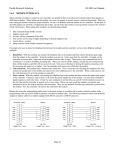
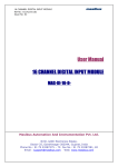
Innovation First
Sep 2005
Spike Blue Relay Module
www.ifirobotics.com
Guide / Page 1
Spike is an H-Bridge relay module custom designed for Robotics applications. The most
common use of Spike is to drive small motors in Forward, Reverse or Off. Spike can also be
used to turn ON or OFF solenoids and lights. Spike takes input power from a 12V battery
(labeled 12V, GND) and provides two outputs (labeled M+, M-). M+ and M- are typically
connected to a motor. The unit is controlled via a three-wire interface, which connects to the
FRC Robot Controller or the Isacc16 Robot Controller. Spike has a 20A integrated fuse to help
protect the unit and it has an indicator to show status.
WARNING. BEFORE APPLYING POWER:
12V Battery
1. Ensure that there is not a short circuit on the output. A short circuit will destroy Spike.
-
-
+
+
Motor,
Light, or
Solenoid
PWM/Relay Cable
FRC-Robot Controller (or Issac16 RC)
Relay Outputs
12V Battery
Figure 1: Spike Blue Wiring to One Motor, Light, or Solenoid
-
+
+
+
Solenoid
Solenoid
Figure 2: Spike Blue Alternate Wiring for Two Solenoids
Notice: This Manual covers the Spike Blue (Not the Spike Red)
-
Innovation First
Sep 2005
Spike Blue Relay Module
www.ifirobotics.com
Guide / Page 2
Motor and Solenoid Wiring
The two motor connections can be wired to either of the relay outputs. M+, and M- are only
labeled to indicate the polarity of the output versus the control signal and Spike’s indicator. If
your motor turns opposite of the direction desired, swap the wires connected to M+ and M-. The
3 wire Control(PWM) cable contains a black wire for ground, a red wire for reverse, and a white
wire for forward. The table below shows the corresponding output versus the control signal and
the indicator.
Table 1: Spike Blue P-BASIC software control, Spike output, Motor function
INPUTS
OUTPUTS
Fwd(Wht) Rev(Red) M+
MIndicator Motor Function
0
0
GND GND Orange
OFF / Brake Condition (default)
1
0
+12v GND Green
Motor rotates in one direction
0
1
GND +12v Red
Motor rotates in opposite direction
1
1
+12v +12v Off
OFF / Brake Condition
Notes:
1. ‘Brake’ refers to the dynamic stopping of the motor due to the shorting of the motor inputs.
This condition is not optional when going to an off state.
2. The INPUT Fwd and Rev are defined as follows: 0 (Off) and 1 (On).
One or Two Solenoid Wiring
The Spike Relay Module can be used to control solenoids. The easiest method of connection is
to wire one side of the solenoid to M+, and the other wire to the ground (GND) side of the
Battery. When the relay is sent a Forward (Indicator Green) command, the solenoid will be
activated. The same can be done with the M- connector to control another solenoid or the
opposite direction of a double solenoid (see Figure 2 on page 1).
Table 2: Spike Blue P-BASIC software control, Spike output, Solenoid function
INPUT
OUTPUTS
Fwd(Wht) Rev(Red) M+
MIndicator Solenoid Function
0
0
GND GND Orange
Both Solenoids OFF (default)
1
0
+12v GND Green
Solenoid connected to M+ is ON
0
1
GND +12v Red
Solenoid connected to M- is ON
1
1
+12v +12v Off
Both Solenoids ON
Note:
1. The INPUT Fwd and Rev are defined as follows: 0 (Off) and 1 (On).
Notice: This Manual covers the Spike Blue (Not the Spike Red)