1
TANK-760 Em b e d d e d S ys te m
S te p 3:
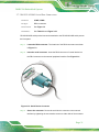
Once aligned, insert the pluggable DC-in terminal block into the DC-in terminal
block connector.
S te p 4:
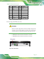
Secure the pluggable DC-in terminal block to the external interface by tightening
the two retention screws on either side of the terminal block (Figure 3-7).
Figure 3-7: Pluggable DC-in Terminal Block Installation
3.5 Fo o t P a d In s ta lla tio n
To install the foot pads, follow the instructions below.
S te p 1:
Turn the TANK-760 to the bottom panel.
S te p 2:
Locate the four retention screw holes for the food pad in the bottom surface.
S te p 3:
Align the hole of the foot pad with the retention screw holes on the bottom
surface.
S te p 4:
P a g e 20
Secure the foot pad to the chassis by four retention screw. S te p 0: