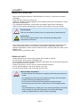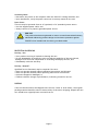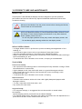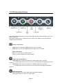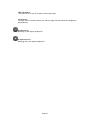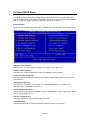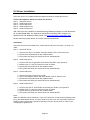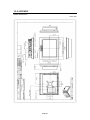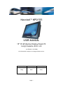
1
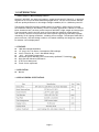
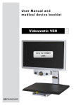
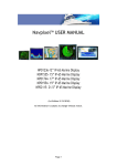
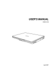
Navpixel™ NPS1535 USER MANUAL 15” IP-65 Marine Display Panel PC Sunlight Readable LED B/L LCD (1st Edition 2/18/2009) All information is subject to change without notice. Approved by Checked by Prepared by Ming Hank Jacky Page 1 RECORD OF REVISION Version and Date Page Old Description Page 2 New Description Remark TABLE OF CONTENT RECORD OF REVISION ........................................................................................................ 2 1.0 INTRODUCTION............................................................................................................ 5 2.0 SAFETY ........................................................................................................................ 7 3.0 9PRODUCT CARE AND MAINTENANCE .......................................................................... 9 4.0 PACKAGING CONTENTS...............................................................................................11 5.0 CONNECTORS............................................................................................................. 12 6.0 INSTALLATIONS .......................................................................................................... 13 7.0 OSD Operation Buttons ............................................................................................. 14 8.0 Award BIOS Setup .................................................................................................... 16 9.0 Driver Installation ...................................................................................................... 18 10.0 APPENDIX................................................................................................................. 20 Page 3 USAGE NOTICE Precautions To maximize the life and safe use of your unit, always be sure to follow the warnings, precautions and maintenance recommendations in this user’s guide. In a Watercraft or Vehicle: z The panel PC should be visible to the driver only if it is used for navigation, or system control. Care should be taken to ensure distraction does not occur. z Review all applicable federal, state and local laws and regulations to make sure the panel PC is used properly and safely. z Avoid using the panel PC for extended times while the charging system is not running, or the panel PC could drain the watercraft’s battery. Cleaning the Panel PC: z Use a soft cloth moistened with mild detergent, isopropyl alcohol, or window cleaners to clean the display housing. z Never use abrasive cleaners, waxes or solvents to clean the unit. Page 4 1.0 INTRODUCTION 1.1 About Navpixel™ Marine Display Panel PC Navpixel™ NPS1535, the high-performance, rugged touch panel PC Panel PC, is specially engineered to survive the most demanding applications. You will soon become familiar with the quality difference in this bright sunlight readable (0.5 to 1,000 nits) panel PC. The Navpixel™NPS1535 sunlight readable panel PC handles a wide-range of extreme environments making it the industry choice for mobile applications. Housed in a milled billet aluminum case, the slim-profile Navpixel™NPS1535 is light weight and watertight. Front-mounted controls and the touch screen make the industrial rugged panel PC user-friendly. We have incorporated the latest optical engineering to achieve optimal viewability in all lighting conditions, including direct sunlight. The Navpixel™NPS1535’s power efficient, low heat design results in increased reliability and longevity required for mission critical deployment. 1.2 FEATURES z z z z z z z z 1000 Nits Sunlight Readable 15” Long Life, Low Power Consumption LED backlight Intel™ Celeron® M / Core 2 Duo Based Design -10ºC ~ 40ºC Wide Temperature Advanced Optical Bonding (AOT) Powered by OptiBond™ Technology High Shock & Vibration Resistance IP-65 Front Waterproof Touch Screen (Optional) 1.3 APPLICATION: z Marine 1.4 DISPLAY GENERAL SPECIFICATI0NS: Page 5 1.5 System GENERAL SPECIFICATI0NS: System Processor ® Supports Intel Core 2 Duo (Merom)/ Core Duo/ Core Solo/ Celeron M (Yonah) Processors System Memory 240-pin DIMM x 2, DDRII 400/533/667 up to 4GB Chipset Ethernet Intel 945GM + ICH7M (-DH optional for RAID) Intel 82573L 10/100/1000Base-TX, RJ-45 x 2 BIOS Award Plug & Play BIOS – 1MB ROM Expansion Interface Power Requirement PCI x 1, PCI-E[x1], Mini PCI x 1 ATX (+3.3V, +5V, +5VSB, +12V) or AT (+5V, +12V) Power Consumption (Typical) T7400 2.16GHz, DDRII 667 2 GB--+12V @ 2.24A, +5V @ 3.6A Operating Temperature Storage Temperature Operating Humidity MTBF -10°C ~ 40°C -20°C ~ 60°C 0%~90% relative humidity, non-condensing 60,000 ® Display: Supports CRT/LCD, CRT/TV, LCD/TV, LCD/DVI and CRT/DVI simultaneous/ dual view display ® Chipset Intel 945GM Memory Shared system memory up to 224MB w/ DVMT3.0 nd LCD Interface 18-bit dual-channel LVDS TFT LCD, 2 24-bit dual-channel LVDS through an optional SDVO card DVI Yes, 2 DVI through an optional SDVO card I/O Storage Serial Port Audio USB K/B and Mouse Power Input nd SATA II x 2, Type II CompactFlash x 1 RS-232 x1, RS-232/422/485 x 1 MIC-In, Line-In, Line-out, CD-in, Stereo amplifier included USB 2.0 x 4 PS/2 Keyboard x 1, and PS/2 Mouse x1 AC110 ~ 240V 9~36VDC (Optional) Page 6 2.0 SAFETY GENERAL SAFETY INSTRUCTIONS • Before operating the Navpixel™ NPS1535 Panel PC Panel PC, read this user manual thoroughly • Keep this user manual for future use • Verify the computer system capability (see Packaging Contents & Installation) to insure operation of the Panel PC • For expeditious installation, follow these user manual instructions in sequence • Adhere to all Caution and Warnings on system and as stated in this user manual Shock Hazards This icon is intended to tell the User of a potential risk of electrical shock. WARNING! Instructional This icon is intended to tell the User of important operating and/or CAUTION! maintenance instructions. • User manual instructions for installation and operation should be followed precisely • Adjust only those controls covered by the user manual’s operating instructions; improper adjustment of other controls voids the unit’s warranty and may result in unit damage, and • Adhere to local installation codes. GENERAL UNIT SAFETY • Always disconnect the unit from the power source before cleaning • Do not operate the unit with a damaged cord • Do not operate if the unit has been dropped or damaged. The unit should be inspected by our qualified Service Personnel • Position the power cord so it is not in contact with hot surfaces • Do not allow anything to rest on the power cord, and • Do not place the power cord in the path of foot traffic. WARNING! General Safety Precautions .Power cord must be connected to a properly wired and grounded power source .Any equipment to which the unit is attached must also be connected to properly wired and grounded power sources .Do not connect or disconnect the unit during an electrical storm .Do not remove the unit covers ? there are no user serviceable parts in the unit .Do not disassemble or modify the unit to avoid the possibility of electrical shock, damage to electrical components or scratching the display surface, and disassembly of the unit voids the warranty. Page 7 Connecting Cables • Disconnect the power to the computer when the Panel PC is being installed, and • Upon installation, verify the power connector is securely seated on the unit. Power Source This unit may be operated from an AC (optional) or DC (standard) power source. • Use the supplied power cable, and • Always connect to a properly grounded power source. EMI / RFI This product has been engineered to meet or exceed international industry CAUTION! standards addressing product design and enclosure protection against EMI/RFI when installed with the factory provided cables PROTECTION ON SERVCING Servicing - User • User product servicing is limited to cleaning the unit • Do not disassemble or modify the unit to avoid the possibility of electrical shock, damage to its electrical components or scratching the display surface, and • Disassembly voids the warranty. Servicing – Navpixel™ Qualified Service Personnel may be required if the unit: • Does not operate normally when installation instructions are followed • Does not operate normally when operating instructions are followed • Has been dropped or damaged, or • Exhibits a distinct change in performance, indicating a need for service. SHIPPING If the unit should need to be shipped to the Service Center or local dealer, the original packing material should be used to insure safety of the unit in shipping. Repack the unit as it would have originally been received from us. Page 8 3.0 PRODUCT CARE AND MAINTENANCE PRODUCT CARE This Navpixel™ NPS1535 Marine Display has been designed to provide optimum performance and service without any required scheduled maintenance other than occasional cleaning. Disconnect the Monitor from the power source before cleaning the Monitor, Touch Screen or unit’s enclosure. WARNING! Do not use abrasive cleaners or solvent-based (flammable) cleaners on the Flat Panel or Touch Screen Display, its enclosure or any other electrical CAUTION! device (cables, power cord, etc) .Do not use paper products as they may scratch the display screen, and .Do not directly apply cleaning solutions to the display screen. DISPLAY SCREEN CLEANING • A vinegar-based cleaner is preferred to prevent streaking and degradation of the coatings, or • A non-abrasive glass cleaner such as a professional foam glass cleaner • Apply the cleaning solution to a soft clean cloth, dampening slightly • Keep a fresh side of the cleaning cloth towards the screen surface to avoid scratching it with accumulated grit, and • To minimize the risk of abrasion to the screen, air drying is recommended. TOUCH SCREEN Touch Screen Cleaning • Use a special screen cleaning tissue or a solution specifically antistatic coatings. Follow the manufacturer’s instructions, • Lightly dampen a soft clean cloth with water or a general detergent solution • Keep a fresh side of the cleaning cloth towards the screen scratching it with accumulated grit, and • To minimize the risk of abrasion to the screen, air drying Panel PC Enclosure • Clean the unit enclosure with a soft clean cloth lightly dampened purpose mild detergent solution • To rinse, wipe down with clean water, and • Dry with a soft clean cloth. Long-term Storage • For long-term storage, it is suggested the unit be stored in a normal indoor environment and the display glass be protected from accidental damage • For pedestal mount units, disconnect the cable(s) and loosen the arm adjustment to a point where the ball can be removed from the arm, or Page 9 • For Flush or Panel Mount units, cover the product with a protective covering that will not scratch or transfer any dyes to the display screen. MAINTENANCE WARNING! Power Cord To avoid shock and fire hazards, replaced the unit’s power cord if: .Insulation becomes damaged, or .A loose connection is suspected. Other Maintenance Only Qualified Service Personnel should perform all other maintenance except for cleaning and the power cord replacement described above. Page 10 4.0 PACKAGING CONTENTS The Navpixel™NPS1535 is shipped in a box with PE foam packaging. It is recommended the installer save the box and all packaging materials in case the unit would need to be returned to the Service Center or local dealer. (Figure 1) One Navpixel™ NPS1535 unit User CD with touch screen driver Four (4) mounting bracket lugs and four (4) stainless steel threaded studs (Figure 1) Page 11 5.0 CONNECTORS 5.1 CONNECTORS Connectors are located on the bottom of the unit housing, from left to right (Figure 2): Connectors are physically unique to insure the installer makes the proper connections. (Figure 2) Page 12 6.0 INSTALLATIONS The Navpixel™ NPS1535 is designed to be mounted in two configurations: 6.1 VESA75 / VESA100 MOUNT The Navpixel™ NPS1535 is designed compatible with VESA75 and VESA100 mount. By installing the panel PC with this kit, the user can adjust the viewing angle to improve viewability in changing environments. This mounting system has proven to be successful in supporting an extreme amount of weight in high vibration and difficult-mount applications. 6.2 PANEL (Flush) MOUNT For installation, there are four tapped mounting holes on the both sides of the unit. The mounting packet is included with the product accessories in the shipping box. This packet includes four (4) stainless steel threaded studs, 3.2 cm and four (4) mounting bracket lugs. Mounting the Panel PC The back of the panel PC includes mounting points that you can use to mount the panel PC as your installation requires. Mounting holes on the Navpixel™ NPS1535 allow the panel PC to be mounted by rear mounted using VESA75 or VESA100 mount Mounting from rear: z VESA75 (4 hole pattern). Accepts M4x0.7 up to 4mm depth. z VESA100 (4 hole pattern) Accepts M4x0.7 up to 4mm depth. Page 13 7.0 OSD Operation Buttons Your Sunlight Readable panel PC can be controlled using the manual buttons on the front bezel of the unit. The manual enables you to change the way in which your display is set up brightness using the manual buttons. Power on/off button Power on: To press the POWER button for start PC system. Power off: To press the POWER button for shut down PC system. Power LED button LED on is for the start PC system mode. LED off is for the shutdown PC system mode. Light Sensor on/off button Light Sensor on: To press the button for enable light sensor function. *** If enable light sensor function can not to use that manual brightness up/down function. Light Sensor off: To press the button for disable light sensor function. *** If disable light sensor function can to use that manual brightness up/down function. Night Mode button Press the button to activate night mode and dim the display. Press again button to return to normal mode. Page 14 HDD LED button The HDD LED is for the PC system access status light. Light Sensor The light sensor is used to detect the ambient light and then adjust the brightness automatically. Brightness Up Dimming up the display brightness. Brightness Down Dimming down the display brightness. Page 15 8.0 Award BIOS Setup Awards BIOS ROM has a built-in Setup program that allows users to modify the basic system configuration. This type of information is stored in battery-backed CMOS RAM so that it retains the Setup information when the power is turned off. Entering Setup Power on the computer and press <Del> immediately. This will allow you to enter Setup. Standard CMOS Features Use this menu for basic system configuration. (Date, time, IDE, etc.) Advanced BIOS Features Use this menu to set the advanced features available on your system. Advanced Chipset Features Use this menu to change the values in the chipset registers and optimize your system performance. Integrated Peripherals Use this menu to specify your settings for integrated peripherals. (Primary slave, secondary slave, keyboard, mouse etc.) Power Management Setup Use this menu to specify your settings for power management. (HDD power down, power on by ring, KB wake up, etc.) PnP/PCI Configurations This entry appears if your system supports PnP/PCI. PC Health Status This menu allows you to set the shutdown temperature for your system. Page 16 Frequency/Voltage Control Use this menu to specify your settings for auto detect DIMM/PCI clock and spread spectrum. Load Fail-Safe Defaults Use this menu to load the BIOS default values for the minimal/stable performance for your system to operate. Load Optimized Defaults Use this menu to load the BIOS default values that are factory settings for optimal performance system operations. While AWARD has designated the custom BIOS to maximize performance, the factory has the right to change these defaults to meet their needs. Set Supervisor/User Password Use this menu to set Supervisor/User Passwords. Save and Exit Setup Save CMOS value changes to CMOS and exit setup. Exit Without Saving Abandon all CMOS value changes and exit setup. Page 17 9.0 Driver Installation Insert the driver CD, please follow the sequence below to install the drivers. Follow the sequence below to install the drivers: Step 1 – Install INF Driver Step 2 – Install VGA Driver Step 3 – Install LAN Driver Step 4 – Install Audio Driver Step 5 – Install SATA Driver USB 2.0 Drivers are available for download using Windows® Update for both Windows® XP and Windows® 2000. For additional information regarding USB 2.0 support in Windows® XP and Windows® 2000, please visit www.microsoft.com/hwdev/usb/. Please read instructions below for further detailed installations. Installation: Insert the CD into the CD-ROM drive. And install the drivers from Step 1 to Step 4 in order. Step 1 – Install INF Driver 1. Click on the Step 1-inf folder and then double click on the setup.exe 2. Follow the instructions that the window shows 3. The system will help you install the driver automatically Step 2 – Install VGA Driver 1. 2. 3. 4. Click on the Step 2-vga folder and choose the folder your system is Double click on .exe file located in each OS folder Follow the instructions that the window shows The system will help you install the driver automatically Step 3 – Install LAN Driver 1. 2. 3. 4. Click on the Step 3-LAN driver folder Select the Windows folder and then double click on Autorun.exe Follow the instructions that the window shows The system will help you install the driver automatically Step 4 – Install Audio Driver 1. 2. 3. 4. Click on the Step 4- AC97 folder and choose the folder your system is Double click on .exe file located in each OS folder Follow the instructions that the window shows The system will help you install the driver automatically Note: Under the Window OS environment, if the CRT connector is connected to display panel PC by the data switch device, the user need to set the color and resolution from Intel Graphic utility (VGA driver) instead of setting from the control panel in case of the wrong display appearance. Page 18 Step 5 – Install SATA Driver 1. Click on the Step 5- ICH7M-GHM SATA Driver Folder 2. Select the Win OS folder and then double click on iatabl_cd.exe 3. Follow the instructions that the windows shows 4. The system will help you install the driver automatically Page 19 10.0 APPENDIX Outline Dimensions Unit: mm Page 20