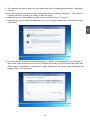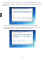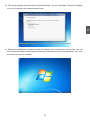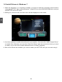
1
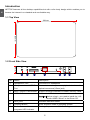
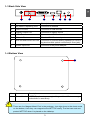
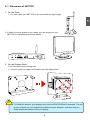
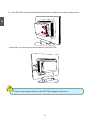
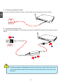
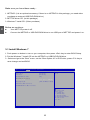
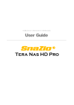
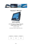
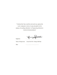
NETTOP User’s Manual
Trademark:
All trademarks are the property of their respective owners.
Version:
User’s Manual V1.3 for NETTOP.
CA
UT
IO
N
Symbol description:
!
Caution : refers to important information that can help you to use NETTOP
better, and tells you how to avoid problems.
WEEE:
The use of this symbol indicates that this product may not be treated as household
waste. By ensuring this product is disposed of correctly, you will help prevent potential
negative consequences for the environment and human health, which could otherwise be caused by inappropriate waste handling of this product. For more detailed
information about recycling of this product, please contact your local city office, your
household waste disposal service or the shop where you purchased this product.
CAUTION
RISK OF EXPLOSION IF BATTERY IS REPLACED
BY AN INCORRECT TYPE
DISPOSE OF USED BATTERIES ACCORDING
TO THE INSTRUCTIONS
© All rights reserved.
All trade names are registered trademarks of respective manufacturers listed.
All images are for reference only, please refer to the physical product for specific features.
CA
UT
IO
N
Safety Notice :
!
Before using this product, please read the below safety notice carefully,
this will help to extend the product’s lifecycle, and work normally.
■ When NETTOP is working, please make sure its ventilation system is
working.
■ The power adapter is dissipating heat during normal use, please be sure
not to cover it and keep it away from your body to prevent discomfort or
injury by heat exposure.
■ Please use the power adapter that comes with the product’s package,
wrong power adapter may damage your device.
■ Make sure all the peripherals are properly connected before using NETTOP.
■ This product should only be used in an environment with ambient temperatures between 0◦C and 40◦C.
■ To reduce the risk of fire, use only No. 26 AWG or larger UL listed or
CSA certified telecommunication line cord.
■ Always shut down the computer before installing or uninstalling the peripheral which does not support hot plug.
■ Disconnect all peripherals before servicing or disassembling this equipment.
■ Please do not disassemble this product by yourself, any disassembly
not approved by the original manufacturer may result in malfunction, and
void warranty.
■ Risk of explosion if battery is replaced by an incorrect type, please dispose of used batteries according to the instructions.
Table of Contents
Chapter 1 Introducing the NETTOP
Top ����
View....................................................................................................2
Front Side ����
View.........................................................................................2
Back Side ����
View.........................................................................................3
............
Bottom View..............................................................................................3
Chapter 2 Placing and connecting the NETTOP
Placement of NETTOP
On the Desk..........................................................................................5
On the Display Back..............................................................................5
Connection of NETTOP
Connect the Antenna.
������� ............................................................................7
Connect the Monitor..............................................................................7
�������
Connect
�����������������������
the �����������
USB Devices.....................................................................7
Connect
�������������������������
the �������������
Network Cable..................................................................8
Connect
����������������������
the ����������
Power Cord.......................................................................8
Chapter 3 Install Windows 7 in NETTOP
Install Windows 7....................................................................................10
Install Drivers in Windows 7....................................................................14
The NETTOP is a compact and easy to use desktop. It features all
the desktop capabilities but with a slim body design which enables
your to browse the internet in a relax and comfortable way.
This chapter introduces NETTOP’s outlook :
■
Top View
■
Front Side View
■
Back Side View
■
Bottom View
1
Introduction
NETTOP features all the desktop capabilities but with a slim body design which enables you to
browse the internet in a relaxable and comfortable way.
1-1 Top View
190mm
135mm
1-2 Front Side View
24mm
1
2
3
4
5
6
7
No. Name
Description
1
Headphone Port
Connects to a headphone
2
Microphone In and S/PDIF In
Port
Connects to a microphone or playback devices with
optical connectors(3.5mm jack)
3
Multi-Function Card Reader
Support SD/SDHC/MS/MS Pro/MMC memory cards
4
USB 3.0 Ports
Connect to USB devices
Caution: Before using it, you need to install the “AS-
Media USB3.0 driver” in the Driver CD.
5
HDD_LED
Indicates hard disk states
6
Suspend Button
Enter suspend mode in operating system
7
Power Button with
Integrated LED Indicator
Turning the power on/off, Indicates
�����������������������
system states
1-3 Back Side View
1
1
2
3
4
5
6
7
No. Name
Description
1
RF(Radio Frequency) Port
Connects to antenna
2
USB 2.0 Ports
Connects to USB devices
3
Display Output Port
Connects to display device
4
HDMI Port
Connects to HDMI audio and video
5
Network Port
Standard RJ-45 network port
6
Line Out and S/PDIF Out Port
Connects to powered analog speakers or recording devices with optical connectors(3.5mm jack)
7
Power Input Port
Connects to the power adapter
1-4 Bottom View
1
No.
1
CA
UT
IO
N
!
Name
Description
Sheet Metal
NETDVD(optional accessary) or Magnet-Metal-Feet can magnetize them to seat firmly
There are four Magnet-Metal-Feet in the package. Just align them to the sheet metal
on the bottom, then they can magnetize the NETTOP easily. The feet can seat and
protect NETTOP when it is placed on the tabletop.
In this chapter, the placement and the connection of some necessary peripherals will be introduced.
This chapter includes the following information:
■
Placement of NETTOP
■
Connection of NETTOP
2-1 Placement of NETTOP
1. On the Desk
1. You can install your NETTOP in the mount like the right image.
2
2. If there is enough space on your desk, you can simply put your NETTOP on the tabletop as shown below.
2. On the Display Back
CA
UT
IO
N
This is the best space-saving way.
1. Use four screws to fasten the bracket onto the display back.
!
To install this bracket, your display must follow VESA75/VESA100 standard. The two
groups of holes on your dispaly have different space between, and they help you
easily fasten the bracket onto your display.
2. Fit the NETTOP into the bracket with power button locating at the top for easy touch.
2
2
1
3. After that, you can connect the antenna to your NETTOP.
CA
UT
IO
N
!
Remove the antenna and lift up the NETTOP straightly to take it out.
2-2 Connection of NETTOP
1. Connect the Antenna
Connect the antenna to the RF port of the NETTOP. You can fold the antenna and rotate it in different angle as you want.
2
1
2
2. Connect the Monitor
Connect a monitor to the NETTOP through DVI connector.
3. Connect the USB Devices
Connect USB devices to the USB ports of the NETTOP, for example, mouse and keyboard.
4. Connect the Network Cable
2
Connect LAN cable to the RJ-45 port, with the other end connected to a hub or switch.
Hub
or
Switch
5. Connect the Power Cord
Connect the power adapter to the power input port of the NETTOP, and push the power button to
start it.
1
Outlet
3
CA
UT
IO
N
2
!
The power adapter is dissipating heat during normal use, please make sure not to
cover it and keep it away from your body to prevent discomfort or injury from heat
exposure.
This chapter introduces the Windows installation :
■
Install Windows 7
■
Install Drivers in Windows 7
Make sure you have these ready :
1. NETDVD. (It is an optional accessory. If there is no NETDVD in this package, you need other
purchase an external USB DVD-ROM drive.)
2. NETTOP driver CD. (In this package)
3. Windows 7 Install CD. (Other purchase)
3
Before we continue :
■
■
Your NETTOP power is off.
Connect the NETDVD or USB DVD-ROM drive to one USB port of NETTOP and power it on.
3-1 Install Windows 7
1. Push power on button to turn on your computer, then press <Del> key to enter BIOS Setup.
2. Put the Windows 7 Install CD into the NETDVD or USB DVD-ROM drive.
3. Select and go to the “Boot” menu, set the “Boot Option #1” to DVD drive, press <F4> key to
save change and exit BIOS.
Aptio Setup Utility - Copyright (C) 2010 American Megatrends, Inc.
Main Advanced Boot Security Save
& Exit
Boot
Boot Configuration Quiet Boot
Fast Boot
Bootup Numlock State
Boot Option Priorities
Boot Option #1
Boot Option #2
[Disabled]
[Disabled]
[On]
Enables/Disables Quiet Boot
option
[USB: Optical DVD RW]
[TEAC DV-W28SS-R W.OA]
Hard Drive BBS Priorities
CD/DVD ROM Drive BBS Priorities
→ ←: Select Screen
↑ ↓: Select Item
Enter: Select
+/-: Change Opt.
F1: General Help
F2: Previous Values
F3: Optimized Defaults
F4: Save & Exit
ESC: Exit
Version 2.10.1206. Copyright (C) 2010 American Megatrends, Inc.
10
4. The computer will reboot, and it will start loading the files for installing the Windows 7 Operating
System.
5. After the computer reboots it will start loading the files for installing Windows 7. Click “Next” to
continue and click “Install now” button to start the setup.
6. When the license terms appear choose accept and click “Next” to continue.
7. It will then ask you to select the installation type. Click “Custom (advanced)” to install a new copy
of Windows.
3
8. The setup will the display the hard disk partitions (160GB, in this example) of your system. If
there were other systems (such as Linux) installed previously, you need select them and click
“Drive options (advanced)” to delete them. When all partitions are clean, setup will display the
biggest size of your hard drive.
11
3
9. In the hard disk size screen, you can click the “new” button to create partitions as you need. In
this example we are creating a 70GB partition to install Windows. Make your modifications and
click “Apply”.
To ensure that all Windows features work correctly, Windows might create additional partitions for system files. So you will see a 100MB partition reserved by system after you
create a partition. Select the 70GB partition and click “Next” to continue.
12
10. The setup program will then start to install Windows 7 on your hard disk. During the installation, your computer will restart several times.
3
11. When the installation is complete, setup will prepare your computer for it’s first use. You can
then follow the steps to select system settings, create an account, set a password...etc, until
the whole process is complete.
13
3-2 Install Drivers in Windows 7
3
1. When the Windows 7 is completely installed, you have to install the necessary drivers before
using the NETTOP. Take out the Windows 7 Install CD from the USB DVD-ROM drive, and put
the NETTOP driver CD inside.
2. Waiting for a few seconds, the main menu will be displayed on the screen.
3. Use these options to install all the drivers for your system. You must click "AMD Chipset Driver"
to install it first. After that, you can click ”One Click Setup” and then choose the items you want
to install, or you can click on each individual driver to install it manually.
4. After all the drivers are installed, you need to restart your NETTOP, then you can start using it.
14