1
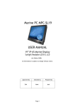
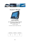
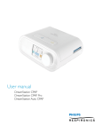
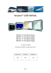
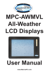
N
W
MARINE PC
E
S
USER MANUAL
15” IP-65 Marine Display
Sunlight Readable LED Backlight LCD
(1st Edition 2009)
All information is subject to change without notice.
Approved by
Erik
Checked by
Hank
Page 1
Prepared by
Mike
RECORD OF REVISION
Version and Date
Mar.2 2009
Page
Old Description
all
New Description
Preliminary Release
Page 2
Remark
TABLE OF CONTENTS
RECORD OF REVISION ........................................................................................................ 2
TABLE OF CONTENTS........................................................................................................... 3
1.0 INTRODUCTION............................................................................................................ 8
2.0 CONTROL AND FEATURES............................................................................................. 9
3.0 INSTALLATION .......................................................................................................... 10
4.0 OSD OPERATIONS....................................................................................................... 16
5.0 TECHNICAL SPECIFICATION ........................................................................................ 25
Page 3
IMPORTANT INFORMATION
EMC conformance
All MarinePC equipment and accessories are designed to the best industry standards for
use in the commercial mari ne environment. The design and manufacture of MarinePC
equipment and accessories conform to the appropriate ElectroMagnetic Compatibility
(EMC) standards, but correct installation is required to ensure that performance is not
compromised.
Waste Electrical and Electronic Equipment Directive
The Waste Electrical and Electronic Equipment (WEEE) Directive requires the recycling
of waste electrical and electronic equipment. Whilst the WEEE Directive does not apply
to some of MarinePC’s products, we support its policy and ask you to be aware of how to
dispose of this product.
The crossed out wheelie bin symbol, illustrated above, and found on our products
signifies that this product should not be disposed of in general waste or landfill. Please
contact the MarinePC factory for more information on product disposal.
Restriction of the use of certain Hazardous Substances
This product uses components that comply with the requirements of the Restriction of
the use of certain Hazardous Substances (RoHS) Directive 2002/95/ EC.
Warranty
This product is warranted to be free from manufacturing defects for a period of two (2)
years parts and one (1) year labor from the date of manufacture. All warranty claims
must be made directly in writing to the MarinePC per the standard published T & C’s.
To obtain a Return Materials Authorization Form, go to www.marinepc.com/Pages/Support.html
Page 4
Packing List
Before installation, please ensure the following items have been shipped:
1 x MPC-SL15 Marine Display
4 x Mounting bracket lugs and 4 stainless steel threaded studs
1 x VGA Cable (3 m.)
If any of these items should be missing or damaged, please contact your distributor
or sales representative immediately.
Page 5
This Page Intentionally Left Blank.
Page 6
Usage Notice
Precautions
To maximize the life and safe use of your unit, always be sure to follow the warnings,
precautions and maintenance recommendations in this user’s guide.
In a Watercraft or Vehicle:
z
The monitor should be visible to the driver only if it is used for navigation, or
system control. Care should be taken to ensure distraction does not occur.
z
Review all applicable federal, state and local laws and regulations to make sure the
monitor is used properly and safely.
z
Avoid using the monitor for extended times while the charging system is not running,
or the monitor could drain the watercraft’s battery.
Cleaning the Monitor:
z
Use a soft cloth moistened with mild detergent, isopropyl alcohol, or window
cleaners to clean the display housing.
z
Never use abrasive cleaners, waxes or solvents to clean the unit.
Page 7
1.0 INTRODUCTION
About the MarinePC SL15 Display
The MPC-SL15 is a high-performance display, eq
uipped with optical bonding AR glass or
sunlight readable touch screen. It is specially engineered to survive the most demanding
applications. You will soon become familiar with the quality difference in this bright
sunlight readable (0.5 to 1,000 nits) monitor.
The range of MarinePC Sunlight Viewable Marine Displays has been developed to be used
as part of an integrated marine navigation system or within an entertainment system.
The displays, available in several sizes, are designed to be waterproof and suitable for
use above or below decks.
The MarinePC MPC-SL15 sunlight readable monitor handles a wide-range of extreme
environments making it the industry choice for mobile applications. Housed in a milled
billet aluminum case, the slim-profile Marin ePC MCP-SL15 is light weight and watertight.
Front-mounted controls and the touch screen make the industrial rugged monitor
user-friendly. We have incorporated the latest optical engineering to achieve optimal
viewability in all lighting conditions, including direct sunlight. The MarinePC MPC-SL15’s
power efficient, low heat design results in increased reliability and longevity required
for mission critical deployment.
This handbook contains important information on the installation, operation and
maintenance of the MarinePC Sunlight Viewable Marine Display range which is intended
for use in the marine market and covers all models.
Page 8
2.0 CONTROL AND FEATURES
Your MarinePC Sunlight Viewable Marine Display has the following controls and features:
Front View
Back View
Page 9
3.0 INSTALLATIONS
It is important that your new display is installed and operated in accordance with the
instructions provided in this handbook. Failure to do so could result in poor product
performance and may invalidate your warranty.
When planning the installation the following points must be considered:
• Your MarinePC display is sunlight viewable and visible in direct sunlight.
• If temperatures exceed the normal temperature operating range the display could
overheat and begin to blackout due to the limitations of TFT LCD technology.
• In order to minimize the chances of a malfunction, the following precautions should be
taken during installation:
• The display should be installed in an area where there is proper and adequate
ventilation. If it is possible to cool the area behind the display, it will significantly
reduce the risk of a malfunction.
• The display should be mounted at an angle to the sun. We do not recommend
mounting the unit in a flat plane, which increases the surface area exposed to the
sun and leads to increased heat absorption.
IMPORTANT: Your MarinePC display is only waterproof from the front. To maintain
watertight integrity the display must be flush mounted ensuring that the rear casing is
enclosed in a watertight enclosure.
The MarinePC MPC-SL15 is designed to be mounted in two configurations:
VESA75 / VESA100 MOUNT
The MarinePC MPC-SL15 is designed compatible with VESA75 and VESA100 mount. By
installing the monitor with this kit, the user can adjust the viewing angle to improve
viewability in changing environments. This mounting system has proven to be successful
in supporting an extreme amount of weight in high vibration and difficult-mount
applications.
The back of the monitor includes mounting points that you can use to mount the monitor
as your installation requires.
Page 10
Mounting holes on the MarinePC MPC-SL15 allow the monitor to be mounted by rear
mounted using VESA75 or VESA100 mount
PANEL (Flush) MOUNT
For installation, there are four tapped mounting holes on the two sides of the unit’s
panel. The mounting hardware packet is included with the product accessories in the
shipping box. This packet includes four (4) stainless steel threaded studs, 3.2 cm and
four (4) mounting lock nuts.
Your monitor can be installed using the mounting lock nuts (supplied) in the vertical
keyways. Make sure that both brackets are in the same orientation.
Preparing the installation site
1. Select an installation site that has sufficient space behind for cable connections and
ventilation.
2. Tape the supplied flush mount template in the required position.
3. Using a jigsaw, carefully remove the shaded portion of the template.
4. Using a suitable file, smooth the edges of the aperture.
Page 11
Installing the display
1. Carefully insert the monitor into the aperture, ensuring that the gasket on the rear of
the fascia lays flat against the aperture edge.
IMPORTANT: The gasket must lay flat against the aperture edge to ensure watertight
integrity.
2. Place the mounting bracket lugs into the keyways and move them to the rear, securing
the bracket to the monitor.
Note: The mounting brackets can be used in either the horizontal or vertical keyways as
required.
3. Using a suitable screwdriver, tighten the mounting bracket screws to secure the
monitor in position.
Page 12
4. Connect all cables as required - see “Rear connections” below.
Rear connections
The rear connectors are:
1.
2.
3.
4.
5.
6.
7.
8.
9.
FUSE
Power Input
DVI Input
VGA Input
CVBS-1 Input (Composite Video) for AV input
CVBS-2 Input (Composite Video) for AV input
CVBS-3 Input (Composite Video) for AV input
USB for Touch control (option)
RS232 Input
Planning the installation
Before you install your display, the following points should be considered:
• Power requirements.
• Display location and mounting options.
• Additional accessories, e.g. keyboard or speakers.
Power requirements
Your Sunlight Viewable display is designed to run on boat’s DC power systems rated at 12
V or 24 V. MarinePC MPC-SL15 is equipped with 9~36V DC wide range power input.
The DC power system can be either:
• Negative grounded, with the negative battery terminal connected to the boat’s
ground,
• Floating, with neither battery terminal connected to the boat’s ground.
Grounding the display
It is important that an effective radio frequency (RF) ground is connected to the display.
You must ground the display by connecting the drain wire (shield) of the power input
block to the nearest ground point of the boat’s RF ground system.
Page 13
Display location and mounting options
Your display can be mounted using the flush mounting kit supplied. MarinePC
recommends that you power the unit and select a suitable mounting location prior to
installing the display.
When planning the display location, the following points should be considered to ensure
safe, comfortable and reliable operation:
• Convenience- the mounting location should be easily accessible to allow operation of
the controls and should enable easy viewing of the display.
Power connections
The power connection to the display should be made at either the output of the battery
isolator switch, or at a DC power distribution panel. MarinePC recommends that power is
fed directly to the display via its own dedicated cable system and MUST be protected by
a thermal circuit breaker or fuse, fitted close to the power connection. If you do not
have a thermal circuit breaker or fuse in your power circuit, you MUST fit an in-line
breaker or fuse to the positive (red) lead of the power cable.
• Installation angle- the display should be mounted at an angle. Mounting it in a flat
plane is not recommended due to increased heat absorption.
• Viewing angle - this LCD has been chosen to give the very best performance, including
viewing angle. However, the contrast and colors seen on all LCD displays vary slightly
with viewing angle.
• Environment - to prevent overheating, do not restrict airflow at the rear of the display
unit; If the space behind the display is air conditioned or cooled by a fan, it will help in
keeping the unit’s temperature down when mounted in direct sunlight.
FAILURE TO ADEQUATELY VENTILATE THE UNIT COULD INVALIDATE YOUR WARRANTY.
The display should be protected from physical damage and excessive vibration.
DO NOT place the display near to a heat source.
Page 14
Typical Installation Diagram
Page 15
4.0 OSD OPERATIONS
Introduction
Your MarinePC Sunlight Viewable display can be controlled using the On Screen Display
(OSD) menu and/or the 8 buttons on the front bezel of the unit.
The OSD menu enables you to change the way in which your display is set up and is
accessed using the Menu button.
Using the buttons
Each of the 8 buttons on the front bezel of your display has an input and a control
function.
Input functions enable you to select the type of signal input to the display.
Control functions enable you to change the appearance of the display.
Power
Power ON Key
To power your monitor ON, just need to press this button.
Power OFF Key
To power your monitor OFF, just press this button.
Pressing the power button will display a list of what input for the main screen is
associated with each button. This is just a reminder and is not part of the input selection
process.
Page 16
BRIGHTNESS Key
When you press the BRIGHTNESS Key, the screen will show the following image
You can press the UP /DOWN Key to do the screen brightness adjustment. When the
brightness achieve 50 and keeping pressing “UP” Key, the dimming will keep the
brightness at 50. When you dimming down to brightness 1 and keeping pressing the
“DOWN” Key, the dimming will keep the brightness at 1.
If you keep pressing “BRIGHTNESS” Key and hold it, the brightness will appear as
following status:
. . . .2
1 → 2→ 3 → . . .
48
49
50
49
48
....
And if you release the “BRIGHTNESS” Key around 5 seconds without any action, the
brightness bar will disappear.
When you press “BRIGHTNESS” Key and another Key (not including Up/Down Key), the
BRIGHTNESS status bar image will disappear.
When you press NIGHT MODE KEY or choose VR adjustment, the BRIGHTNESS KEY will
not function if you press it.
VR BRIGHTNESS Key
If you want to enable the VR Brightness function, you need to press “MENU” KEY and
then choose VR function. When you rotate the VR knob, the VR BRIGHTNESS status bar
will appear as below image (dimming range from 1~15):
When you enter the VR BRIGHTNESS mode, the BRIGHTNESS button will not be operational.
If you release the VR knob without any action for around 5 seconds,
the VR BRIGHTNESS Status bar image will be closed.
When you enter the “NIGHT MODE” or choose “BRIGHTNESS” button for brightness
adjustment, the VR knob will not be operational.
When you press “MENU”, “INPUT” Key, you will enter the menu item selection. And the
VR BRIGHTNESS status bar image will be closed.
Any modified or changed parameter setting will be automatically saved if you power off
or Exit the BRIGHTNESS status bar.
Page 17
NIGHT MODE KEY
When you press the “NIGHT MODE” KEY, the dimming will be down to under 0.5 nit
directly. And if you press “BRIGHTNESS” KEY or “VR” knob at this moment, it will be no
function until you press the “NIGHT MODE” KEY again to release this restriction.
When you press “MENU”, “INPUT” Key, you will enter the menu item selection.
Any modified or changed parameter setting will be automatically saved if you power off
or Exit the NIGHT MODE.
UP
/ DOWN
KEY
It works as menu item selection use, the “UP”KEY can be used as “RIGHT” KEY and the
“DOWN” KEY can be used as “LEFT”KEY.
INPUT KEY
When you press “INPUT” KEY, the screen will pop up the following image:
You can press the “UP”/ ”DOWN” KEY for the menu item selection above. It will remain
at “VIDEO 3” position if you keep pressing “DOWN” KEY to the end. And it will also
remain at “RGB1” position if you keep pressing “UP” KEY to the end.
When you press and hold the “INPUT” KEY, the menu screen will show as
RGB1→DVI 1→..→VIDEO3→VIDEO2→..
If you release the “INPUT” KEY for 5 seconds without any action, the menu selection
screen will be closed. And it will remain at the item which you’d selected.
When you press “MENU”, “BRIGHTNESS” Key, you will enter respective item selection.
Any modified or changed parameter setting will be automatically saved if you power off or
Exit the menu setting screen.
Page 18
MENU KEY
When you press “MENU” KEY, the MarinePC OSD main menu screen will appear as below:
If you release the “MENU” KEY for 30 seconds without any action, the menu OSD screen
will disappear automatically. You can also choose “QUIT” and then press “MENU” KEY to
exit this OSD menu screen.
RGB Setting Item Description:
・ PHASE――― Horizontal Sampling Phase Adjustment。
・ CONTRAST――― Contrast Adjustment。
・ H_POSITION―― Horizontal Screen Adjustment。
・ V_POSITION―― Vertical Screen Adjustment。
・ R_LEVEL――― Red Color level Adjustment。
・ G_LEVEL――― Green Color level Adjustment。
・ B_LEVEL――― Blue Color level Adjustment。
・ TEMPERATURE――― Color Temperature Adjustment。
・ EXIT――― Quit from current setting。
Page 19
DVI 1’s setting screen:
DVI Setting Item Description:
・ CONTRAST―――Contrast Adjustment。
・ R_LEVEL――― Red Color level Adjustment。
・ G_LEVEL――― Green Color level Adjustment。
・ B_LEVEL――― Blue Color level Adjustment。
・ TEMPERATURE――― Color Temperature Adjustment。
・ EXIT――― Quit from current setting。
Page 20
VIDEO 1 & 2 & 3’ setting screen:
VIDEO Setting Item Description:
・ CONTRAST――― Contrast Adjustment。
・ SHARPNESS――― Horizontal edge sharpness
・ R_LEVEL――― Red Color level Adjustment。
・ G_LEVEL――― Green Color level Adjustment。
・ B_LEVEL――― Blue Color level Adjustment。
・ TEMPERATURE――― Color Temperature Adjustment。
・ EXIT――― Quit from current setting。
Page 21
OSD setting screen:
OSD Setting Item Description:
・ H_POSITION―― Horizontal Screen Adjustment。
・ V_POSITION―― Vertical Screen Adjustment。
・ BRIGHTNESS――― Selection between “BRIGHTNESS” key or “VR” Button for
brightness adjustment。
・ SYSTEM RETURN――― Restore all parameter setting to factory default value。
・ EXIT――― Quit from current setting。
Page 22
SYSTEM RETURN setting screen:
You may choose “SYSTEM RETURN” selection item on the OSD Screen to restore all of the
parameter setting to factory default value. When you press “UP” or “RIGHT” KEY, the
parameter will show “YES” and confirm it.
Page 23
“KEY LOCK” Mode Function setting screen:
When you press “MENU” and “BRIGHTNESS” KEY simultaneously for 3 seconds, you will
enter the “KEY LOCK” mode. At the same time, the screen will show “KEY LOCK” image
as below for 5 seconds and then disappear.
In the “KEY LOCK” mode, there will be no function pressing any key. When you press a key
in the “KEY LOCK” mode, the screen will show “KEY LOCK” image as below for 5 seconds
and then disappear.
To Release/Unlock “KEY LOCK” Mode Function setting screen:
In the “KEY LOCK” mode, when you press “MENU” and “BRIGHTNESS” KEY simultaneously
for 3 seconds, you will release/unlock the “KEY LOCK” mode. At the same time, your
screen will show “KEY UNLOCK” image as below.
Page 24
5.0 TECHNICAL SPECIFICATION
5.1 General Specification
LCD Display
Backlight
15" LED Backlight
Active Display Area
Brightness
304.128 x 228.096 mm
Resolution
1024x768 (XGA)
Contrast Ratio
Pixel Pitch (mm)
700:1
0.297(H) x 0.297 (V)
Viewing Angle
160 (H), 160(V)
Display Color
16.2M
Response Time
Tr:8ms, Tf:17ms
Inputs
VGAx1, DVIx1, Composite x3, RS232x1
1000 cd/m2 *
Mechanical
IP Rating
Front waterproof to IP65 standards when
console mounted.
Construction
Rugged Aluminum Alloy Chassis
Mounting
Panel (Flush) mount, VESA mount
Dimension
352.8(W)x303.3(H)x56(D)
Power
Voltage
Operates on 12V and 24V systems
Power Consumption
63W
Environmental
Operating Temperature
-10°C~50°C
Non-Operating Temperature
-20°C~70°C
Certification
Designed to meet FCC Class A,
Marine standard EN60945
* The brightness is measured under the 25°C ambient temperature before touch
attached.
Page 25
5.2 ME Drawing
Dimension
MPC-SL15
Page 26