1
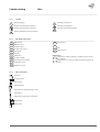
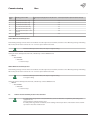
Commissioning
Atec
www.thermia.com
Thermia Värmepumpar is not liable or bound by warranty if these
instructions are not adhered to during installation or service.
The English language is used for the original instructions.
Other languages are a translation of the original instructions.
(Directive 2006/42/EC)
© Copyright Thermia Värmepumpar
Commissioning
Atec
Table of Contents
1
About documents and decals . . . . . . . . . . . . . . . . . . . . . . . . . . . . . . . . . . . . . . . . . . . . . . . . . . . . . . . .
1.1 Introduction . . . . . . . . . . . . . . . . . . . . . . . . . . . . . . . . . . . . . . . . . . . . . . . . . . . . . . . . . . . . . . . .
1.2 Symbols in documents . . . . . . . . . . . . . . . . . . . . . . . . . . . . . . . . . . . . . . . . . . . . . . . . . . . . . . . . . .
1.3 Symbols on decals . . . . . . . . . . . . . . . . . . . . . . . . . . . . . . . . . . . . . . . . . . . . . . . . . . . . . . . . . . . .
4
4
4
4
2
Checking piping and electrical installation . . . . . . . . . . . . . . . . . . . . . . . . . . . . . . . . . . . . . . . . . . . . . . .
2.1 Checking the piping installation . . . . . . . . . . . . . . . . . . . . . . . . . . . . . . . . . . . . . . . . . . . . . . . . . . . .
2.2 Checking the electrical installation . . . . . . . . . . . . . . . . . . . . . . . . . . . . . . . . . . . . . . . . . . . . . . . . . .
6
6
7
3
Filling and bleeding . . . . . . . . . . . . . . . . . . . . . . . . . . . . . . . . . . . . . . . . . . . . . . . . . . . . . . . . . . . . . .
8
4
Setting heat pump size . . . . . . . . . . . . . . . . . . . . . . . . . . . . . . . . . . . . . . . . . . . . . . . . . . . . . . . . . . . .
4.1 Setting heat pump size . . . . . . . . . . . . . . . . . . . . . . . . . . . . . . . . . . . . . . . . . . . . . . . . . . . . . . . . .
9
9
5
Configuration of control system . . . . . . . . . . . . . . . . . . . . . . . . . . . . . . . . . . . . . . . . . . . . . . . . . . . . . .
5.1 Select display language . . . . . . . . . . . . . . . . . . . . . . . . . . . . . . . . . . . . . . . . . . . . . . . . . . . . . . . . .
5.2 Factory setting . . . . . . . . . . . . . . . . . . . . . . . . . . . . . . . . . . . . . . . . . . . . . . . . . . . . . . . . . . . . . . .
5.3 Activation of optimum circulation (variable speed) pump . . . . . . . . . . . . . . . . . . . . . . . . . . . . . . . . . . .
5.4 Set hot water start temperature and activate hot water . . . . . . . . . . . . . . . . . . . . . . . . . . . . . . . . . . . . .
5.5 Activate the electrical auxiliary heater in Atec Plus and Atec Total . . . . . . . . . . . . . . . . . . . . . . . . . . . . . .
5.6 Activate electrical auxiliary heater in Atec Standard . . . . . . . . . . . . . . . . . . . . . . . . . . . . . . . . . . . . . . .
5.7 Activate active cooling . . . . . . . . . . . . . . . . . . . . . . . . . . . . . . . . . . . . . . . . . . . . . . . . . . . . . . . . . .
5.8 Distribution circuits . . . . . . . . . . . . . . . . . . . . . . . . . . . . . . . . . . . . . . . . . . . . . . . . . . . . . . . . . . . .
10
10
10
11
11
12
13
14
15
6
Find start flow . . . . . . . . . . . . . . . . . . . . . . . . . . . . . . . . . . . . . . . . . . . . . . . . . . . . . . . . . . . . . . . . . .
6.1 Finding a start flow . . . . . . . . . . . . . . . . . . . . . . . . . . . . . . . . . . . . . . . . . . . . . . . . . . . . . . . . . . . .
16
16
7
Manual test . . . . . . . . . . . . . . . . . . . . . . . . . . . . . . . . . . . . . . . . . . . . . . . . . . . . . . . . . . . . . . . . . . . .
19
8
Starting up . . . . . . . . . . . . . . . . . . . . . . . . . . . . . . . . . . . . . . . . . . . . . . . . . . . . . . . . . . . . . . . . . . . . .
24
9
Tuning the system . . . . . . . . . . . . . . . . . . . . . . . . . . . . . . . . . . . . . . . . . . . . . . . . . . . . . . . . . . . . . . . .
26
10
Installation protocol and customer info . . . . . . . . . . . . . . . . . . . . . . . . . . . . . . . . . . . . . . . . . . . . . . . . .
29
11
Important information/Safety regulation . . . . . . . . . . . . . . . . . . . . . . . . . . . . . . . . . . . . . . . . . . . . . . . .
11.1 General safety precautions . . . . . . . . . . . . . . . . . . . . . . . . . . . . . . . . . . . . . . . . . . . . . . . . . . . . . . .
11.2 Refrigerant . . . . . . . . . . . . . . . . . . . . . . . . . . . . . . . . . . . . . . . . . . . . . . . . . . . . . . . . . . . . . . . . .
11.3 Electrical connection . . . . . . . . . . . . . . . . . . . . . . . . . . . . . . . . . . . . . . . . . . . . . . . . . . . . . . . . . . .
11.4 Water quality . . . . . . . . . . . . . . . . . . . . . . . . . . . . . . . . . . . . . . . . . . . . . . . . . . . . . . . . . . . . . . . .
11.5 Commissioning . . . . . . . . . . . . . . . . . . . . . . . . . . . . . . . . . . . . . . . . . . . . . . . . . . . . . . . . . . . . . .
30
30
31
32
32
33
Thermia Värmepumpar
VIGFG102
3
Commissioning
Atec
1
About documents and decals
1.1
Introduction
The following documents are available for this product:
▪ Installation quick guide containing information to install a heat pump. Supplied with the heat pump on delivery.
▪ The Service instructions contain information about the heat pump’s function, accessories, fault tracing and technical data. The instructions also contain tips and advice that should be followed before a heat pump installation. It is therefore recommended that
the instructions are read before installation. The Service instructions are available for download as below.
▪ The Wiring diagrams that contain the wiring diagram for the heat pump intended for fault tracing and service. The Wiring diagrams
are available for download as below.
▪ The User manual must handed over and gone through with the end customer. Supplied with the heat pump on delivery.
▪ Country specific instructions and forms are available where relevant. Supplied with the heat pump on delivery.
▪ Self-adhesive decals with translation text. Must be placed on the manufacturing plate in conjunction with installation. Supplied
with the heat pump on delivery.
The Service instructions and Wiring diagrams are available for download here:
www.thermia.com/documents
1.2
Symbols in documents
The instructions contain different warning symbols, which, together with text, indicate to the user that there are risks involved with actions to be taken.
The symbols are displayed to the left of the text and three different symbols are used to indicate the degree of danger:
Danger
Indicates an immediate danger that leads to fatal or serious injury if necessary measures are not taken.
Warning
Risk of personal injury!
Indicates a possible danger that can lead to fatal or serious injury if necessary measures are not taken.
Caution
Risk of installation damage.
Indicates a possible hazard that can lead to item damage if necessary measures are not taken.
A fourth symbol is used to give practical information or tips on how to perform a procedure.
N
1.3
Information regarding making the handling of the installation easier or a possible operational technical disadvantage.
Symbols on decals
The following symbols can occur on decals on the different parts of the heat pump. Which symbols are used depends on the heat pump
model.
4
VIGFG102
Thermia Värmepumpar
Commissioning
1.3.1
!
!
Atec
General
Warning, danger!
Warning, hot surfaces!
Read the documentation provided.
Warning, moving parts!
Read the documentation provided.
Warning, risk of crushing injury!
Warning, hazardous electrical voltage!
1.3.2
3
50
54
55
71
353
362
304
363
365
366
1.3.3
Electrical components
Outdoor unit
Outdoor sensor
Hot water sensor
Hot water top sensor
Flow guard
Drip tray
Shunt valve
Circulation pump
Exchange valve hot water
Supply line sensor
406 Room sensor
or
62
408 EVU
417 Defrost sensor
Explanation
Component, ordinary delivery according to proposed system solutions
Component, accessorie according to proposed system solutions
Return line sensor
Pipe connections
Tap water
Heating system
Brine system
Defrosting tank
Expansion tank with safety valve, brine
Air bleeding
Temperature and pressure relief valve
Outdoor unit
Water heater
Thermia Värmepumpar
VIGFG102
5
Commissioning
Atec
2
Checking piping and electrical installation
2.1
Checking the piping installation
Before filling the heating system, check the piping installation according to the checklist below.
For further information, also see the Installation Quick Guide.
Piping checklist
Are the pipe connections in accordance with the connection diagram?
Are the flexible hoses on the supply and return lines installed on the outdoor unit?
Is the strainer on return line mounted? See figure 1
Is an expansion vessel installed?
Is a valve-pipe with safety valve and manometer installed?
Is a volume tank installed? See Volume tank table below
Is a filler cock with non-return valve heating system installed?
D
C
OK
Not OK
A: Stopcock
B: Cover
C: Strainer
D: O-ring
B
A
Fig. 1: Strainer
Warning
In order to secure the defrosting of the outdoor unit, a minimum amount of water must be contained in the
heating system. This is shown in the table below.
If the heating system itself holds the amount of water described in the table, a volume tank is not needed, but recommended.
Volume tank table
Min water volume in heating system. Atec Standard and
Atec Plus
Min water volume in heating system. Atec Total
N
6
Unit
l
6 kW
120
9 kW
180
11 kW
220
13 kW
260
16 kW
320
18 kW
360
l
60
90
110
130
160
180
If the amount of water in the heating system is not sufficient, Low Pressure alarms may occur.
For Atec Total, also check:
Water heater checklist
Bleed valve installed
OK
Not OK
For Atec Standard, also check:
External Water heater checklist
Exchange valve installed (factory installed in Atec Plus and Atec Total)
OK
Not OK
VIGFG102
Thermia Värmepumpar
Commissioning
2.2
Atec
Checking the electrical installation
Before turning on electrical power, check the electrical installation according to the checklist below
Electrical installation checklist
Are circuit-breakers installed?
One for indoor unit and one for outdoor unit (not included in the delivery)
Are correct fuses installed? See fuse table below
Positioning of the outdoor sensor. See image below
Is communication cable between heat pump and control centre connected? See Installation Quick Guide.
Especially check the shield connection.
Communication cable must be 2 pair shielded Twisted Pair and UV resistant for outN
door use.
OK
Not OK
Fuse table
Heat pump and control
units
230V 1-N 50Hz heat pump
230V 1-N, 50Hz control unit
Unit
6 kW
9 kW
A
A
20
400V 3-N 50Hz heat pump
400V 3-N, 50Hz control unit
A
A
10
11 kW
13 kW
16 kW
32
18 kW
—
1617/3018/4019
16
1012/1613/1614/2015/2516
12) Heat pump with 3 kW additional heater.
13) Heat pump with 6 kW additional heater.
14) Heat pump with 9 kW additional heater.
15) 12 kW additional heater. (Compressor off). Power step 4
16) 15 kW additional heater. (Compressor off). Power step 5
17) Heat pump with 3 kW additional heater.
18) Heat pump with 6 kW additional heater.
19) Heat pump with 9 kW additional heater.
Positioning of the outdoor sensor
Thermia Värmepumpar
H
2/3 x H
Recommended location
Unsuitable location
▪ Position the outdoor sensor on the north or north west side of the
house.
▪ Make sure that the outdoor sensor is not placed in direct sun light.
▪ For higher buildings, the sensor should be positioned between the
second and third storeys. Its location must not be completely protected from the wind but not in a direct draft. The outdoor sensor
should not be placed on reflective panel walls.
▪ The sensor must be positioned at least 1 m from openings in the
walls that emit hot air.
▪ If the sensor cable is connected through a pipe, the pipe must be
sealed so that the sensor is not affected by outgoing air.
VIGFG102
7
Commissioning
3
Atec
Filling and bleeding
1.
2.
3.
4.
5.
6.
7.
Fill the system with cold water by opening the filler valve, that is on the valve pipe, to a pressure of 1 bar.
Open all radiator valves fully.
Bleed all radiators.
Bleed the outdoor unit. See figure 3.
Refill the heating system to a pressure of min. 1 bar.
Repeat the procedure until all air has been removed.
Check the system for leakage.
The system must be filled with antifreeze protection when the outdoor unit is operating in cooling mode under a set temperature value under (< 15°C ). The reason is to avoid the potential risk of freezing of the outdoor
unit.
N
Leave all radiator valves fully open.
N
To bleed the out door unit, remove the lower front hatch and right hand side cover.
atec-042
N
Fig. 3: Bleed the outdoor unit
atec-043
T25
T25
Fig. 2: Remove front hatch and side cover
8
VIGFG102
Thermia Värmepumpar
Commissioning
Atec
4
Setting heat pump size
4.1
Setting heat pump size
N
The default heat pump size setting at shipping is NO SIZE (indicated by an asterisk next to the English text).
This means that the compressor cannot start and the installer must select a heat pump size before leaving this
menu. After the size has been set a factory reset starts and radiator heating appears as the first choice.
When power is supplied to the control unit, the first menu that appears in the display is the DIRECT EVAP. Menu. A heat pump size must
be set before configuring the control system and completing the commissioning.
To set the heat pump size initially:
▪ Use the + or – buttons to select heat pump size in kW.
▪ Press right arrow (>) to confirm the choice. An asterisk (*) will appear next to the chosen value.
▪ Press left arrow (<) and wait until the default screen is displayed.
N
It is possible to select the heat pump size at a later stage by changing the settings in the Service Menu as
described below.
To enter the Service Menu, press and hold left arrow (< for at least 5 seconds. Use + or – to move up and down in the menu.
Set the output size of the heat pump in the menu:
▪ SERVICE
▪ INSTALLATION
▪ SYSTEM
▪ HEAT SOURCE
▪ AIR
▪ DIRECT EVAP.
▪ Press right arrow (>) for approximately 20 seconds to enter the Heat Pump size entry.
▪ Use + or – buttons to select Heat Pump size in kW.
▪ Press right arrow (>) to confirm the choice. An asterisk (*) will appear next to the chosen
value.
▪ Press left arrow (<) several times to navigate back to the Service Menu.
Thermia Värmepumpar
VIGFG102
9
Commissioning
5
Atec
Configuration of control system
N
N
N
Before configuring the control system, the installation must be completed according to the instructions in the
preceeding chapters.
To avoid alarms during start-up, the outdoor unit must be powered on.
Make the settings in the order they appear in the text that follows.
Further information about parameters in the control system are found in the Information Menu and Service Menu chapters in the Technical Description.
5.1
Select display language
After the heat pump size has been set, it is possible to select the display language. It is also possible to go back and change the size
setting using the desired language.
The following settings are made in the Information Menu. To enter the Information Menu, press left arrow(<). Use + or – to move up and
down in the menu.
Select display language in the INFORMATION menu:
▪ INFORMATION
▪ Press – button several times to get to the LANGUAGE entry.
▪ Press right arrow (>) button to enter the LANGUAGE menu.
▪ Use + or – buttons to navigate to the desired language.
▪ Press right arrow (>) to chose language. An asterisk (*) will appear next to chosen language.
▪ Press left arrow (<) twice to exit the Information Menu.
5.2
Factory setting
N
Each time a factory reset is executed, parameters like AUX. HEATER, DEFROST, OPTIMUM, HOT WATER, and
HEAT CURVE return to their default values. This means that parameters like AUX. HEATER, OPTIMUM, and HOT
WATER will not be active until manually activated.
The following settings are made in the Service Menu. If not already in the Service Menu, enter the Service Menu by pressing and holding
left arrow (<) for at least 5 seconds. Use + or – to move up and down in the menu.
Make a factory setting and select heating system with the parameters in the SERVICE menu:
▪ SERVICE
▪ INSTALLATION
▪ FACTORY SET
▪ Use + or – buttons to select FLOOR or RADIATOR. If CANCEL is selected, the system is reset to the default delivery
setting.
▪ Press right arrow (>) to select the appropriate value. If the system is a mix of radiator and floor heating, RADIATOR is chosen.
▪ An asterisk (*) will appear to confirm the setting .
▪ To exit factory setting, press left arrow (<) 5 times to enter Service Menu.
10
VIGFG102
Thermia Värmepumpar
Commissioning
5.3
Atec
Activation of optimum circulation (variable speed) pump
N
N
The Optimum circulation pump is factory installed in Atec Plus and Atec Total.
The OPTIMUM option is however not activated from factory.
If fixed speed circulation pump is used, which may be the case for Atec Standard, then skip this setting.
The following settings are made in the Service Menu. If not already in the Service Menu, enter the Service Menu by pressing and holding
left (<) arrow for at least 5 seconds. Use + or – to move up and down in the menu.
Activation of optimum (variable speed) pump in the SERVICE menu:
▪ SERVICE
▪ INSTALLATION
▪ SYSTEM
▪ OPTIMUM
▪ Press right arrow (>) to enter the optimum function.
The off symbol ( ) is shown.
▪ Press + to activate the optimum function.
▪ ON will appear to confirm the setting.
5.4
Set hot water start temperature and activate hot water
The default hot water start temperature is 40°C.
If another start temperature is desired, change the start temperature setting in the Service Menu. If not already in the Service Menu,
enter the Service Menu by pressing and holding left arrow (<) for at least 5 seconds. Use + or – to move up and down in the menu.
Setting the hot water start temperature in the SERVICE menu:
▪ SERVICE
▪ Press right arrow (>) to enter HOT WATER menu
▪ Press right arrow (>) to activate START sub menu
▪ Press plus + to enter START sub menu
▪ Press plus + to set the desired temperature.
▪ Press left arrow (<) several times to exit the Service Menu
Activate hot water production
The following settings are made in the Information Menu. To enter the Information Menu, press left arrow (<). Use + or – to move up and
down in the menu.
Thermia Värmepumpar
VIGFG102
11
Commissioning
Atec
Activating the hot water production in the INFORMATION menu:
▪ INFORMATION
▪ Press minus - to get to the HOT WATER entry.
▪ Press right arrow (>) to select hot water.
▪ Press right arrow (>) to activate hot water sub menu.
▪ Press plus + to activate the hot water production.
▪ ON will appear to confirm the setting.
▪ Press left arrow (<) several times to exit the Information Menu.
N
5.5
When the operation is set to HOT WATER mode, the reversing valve hot water is set towards the heating system. To minimize the risk that the outdoor unit freezes at low outdoor temperatures (that is, below 5°C) the
reversing valve hot water is set towards the water heater and the circulation pump starts to ensure a sufficient
flow. When the outdoor temperature is above 5°C, the circulation pump stops and the reversing valve hot
water is set towards the house (the heating system) again.
Activate the electrical auxiliary heater in Atec Plus and Atec Total
If the heat demand is greater than the heat pump’s compressor capacity, the immersion heater engages automatically in operating
mode AUTO. Atec Plus and Atec Total has three outputs, IMM. HEAT 1, IMM. HEAT 2 and IMM. HEAT 3 and output can be controlled in
five steps.
The two power steps, step 4 and step 5 for Atec Plus and Atec Total cannot be activated when the compressor is running. Immersion
heater step: +4 and +5 can be selected when the compressor is running and must only be selected on the condition that the building
where the heat pump is installed has a large heating demand and the building’s electrical installation is suitable for high current consumption. In the event of an alarm, the immersion heater engages automatically on the condition that operating mode AUTO is selected
and that at least one additional step is permitted.
In Atec Plus and Atec Total a multi power stage heater (IMM HEATER) is factory installed. The heat pump control system engages the
appropriate amount of heating power to ensure the desired heating system temperature. Below is a table describing the different power
steps.
In power steps 1 – 3, +4 and +5, the compressor and the electrical auxiliary heater can be engaged at the same time. In power steps 4
and 5 only the electrical auxiliary heater is engaged.
N
Caution
12
Power steps +4 and +5 can only be engaged for 400V 3-N electrical auxiliary heater
Check installed fuses before making any settings.
VIGFG102
Thermia Värmepumpar
Commissioning
Power
steps
1
2
3
4
5
+4
Atec
Heating power in kW
Control panel (single phase 1-N) fuse size
(A)
3, immersion heater only
16
6, immersion heater only
30
9, immersion heater only
40
12, immersion heater only
—
15, immersion heater only
—
12, immersion heater + com- —
pressor
15, immersion heater + com- —
pressor
+5
Control panel (three phase 3-N) fuse size (A)
10
16
16
20
25
25
25
230V 1-N Electrical auxiliary heater
The following settings are made in the Service Menu. If not already in the Service Menu, enter the Service Menu by pressing and holding
left arrow (<) for at least 5 seconds. Use + or – to move up and down in the menu.
N
Electrical auxiliary heater for 230V, 1-N. Step 3 is highest setting.
Setting of electric auxiliary heater for 230V, 1-N. Max step 3 in the SERVICE menu:
▪ SERVICE
▪ AUX. HEATER.
▪ MAX STEP
▪ Select max step.
400V 3-N Electrical auxiliary heater
The following settings are made in the Service Menu. If not already in the Service Menu, enter the Service Menu by pressing and holding
left arrow (<) for at least 5 seconds. Use + or – to move up and down in the menu.
N
Electrical auxiliary heater for 400V, 3-N. Step 5 is highest setting.
5 is highest setting
Setting of electrical auxiliary heater for 400V, 3-N. Max step 5 in the SERVICE menu:
▪ SERVICE
▪ AUX. HEATER.
▪ MAX STEP
▪ Select max step.
5.6
Activate electrical auxiliary heater in Atec Standard
N
Thermia Värmepumpar
If a single power stage heater is used (on/off heater, can be an oil burner or equivalent), this setting is the
appropriate one.
The potential free outputs must be used.
If a multi power stage heater is installed, use the settings in the chapter above: "Activate the electrical auxiliary heater in Atec Plus and Atec Total"
VIGFG102
13
Commissioning
Atec
The following settings are made in the Service Menu. If not already in the Service Menu, enter the Service Menu by pressing and holding
left (<) arrow for at least 5 seconds. Use + or – to move up and down in the menu.
Activating the electric auxiliary heater in the SERVICE menu:
▪ SERVICE
▪ AUX HEATER
▪ MAX STEP
▪ P
▪ Press left arrow (<) several times to exit the Service Menu.
5.7
Activate active cooling
The cooling function is primarily temperature controlled and starts when the return line sensor reaches the set value for START. Default
setting is OFF .
The heating system is cooled by reversing the heating process and distributing cold water on to the heating system.
The following settings are made in the Service Menu. If not already in the Service Menu, enter the Service Menu by pressing and holding
left arrow (<) for at least 5 seconds. Use + or – to move up and down in the menu.
Activating active cooling in the service menu:
▪ SERVICE
▪ COOLING
▪ INTEGRATED IN HP
▪ Press right arrow (>) to activate. An asterisk (*) appears.
Active cooling is configured by the parameters shown below:
Parameter
Meaning
COOLING TIME
When the heat pump must alternate between different demands for example heating, hot water, pool heating
and cooling, cooling will be produced according to the set number of minutes.
Factory setting: 20M, range: 5M — 40M
MAX START TEMP
Outdoor temperature when the cooling should start.
Factory setting: 30°C, range: COOLING->START — 55°C
MIN STOP TEMP
Supply line temperature when the cooling should stop.
NOTE: Too low temperature may result in condensation on the radiators.
Factory setting: 16°C, range: 5°C — COOLING->STOP
ROOM SENSOR
Activation of room sensor function for influencing cooling production.
NOTE: Room sensor must be installed and activated.
— ON
Factory setting: , range:
COOL.HYST.RS
LOW
COOL.HYST.RS
HIGH
This setting is available only if ROOM SENSOR is activated
The compressor is stopped if the temperature from the room sensors drops below the desired temperature minus the value set in COOL.HYST.RS LOW.
Factory setting: +1°C
This setting is available only if ROOM SENSOR is activated
The compressor is started when the temperature rises above the desired temperature plus the value set in
COOL.HYST.RS HIGH.
Factory setting: +1°C
14
VIGFG102
Thermia Värmepumpar
Commissioning
5.8
Atec
Distribution circuits
N
The only use for a mixing valve is in a heating system with an external heat source (an oil burner or equivalent) or where there are more than one heating circuits, for example a mix of radiator and underfloor heating.
There are three available mixing valve options:
▪ Mixing valve (Activation, see chapter "Activate the external auxiliary heater in Atec Standard")
▪ Distribution circuit (DISTR. CIRCUIT) 1
▪ Distribution circuit (DISTR. CIRCUIT) 2
The mixing valve is used between the heat pump, an external auxiliary heater (may be an oil burner or equivalent) and the heating
system. The purpose of this valve is to mix cold water into the heated water from the external auxiliary heater (on/off heater) to ensure
that the temperature out on the heating system is not too high. The control system in the heat pump controls the mixing of hot and cold
water out on the heating system.
Distribution circuits 1 and 2 are used where there are more than one heating circuit, for example a mix of radiator and underfloor
heating. The purpose of these distribution circuits are to supply a preset temperature to each one of the heating circuits.
Activating DISTR. CIRCUIT 1
The following settings are made in the Service Menu. If not already in the Service Menu, enter the Service Menu by pressing and holding
left arrow (<) for at least 5 seconds. Use + or – to move up and down in the menu.
Activating distribution circuit 1 in the SERVICE menu:
▪ SERVICE
▪ INSTALLATION
▪ SYSTEM
▪ DISTR. CIRCUIT 1
▪ HEAT CURVE or CONSTANT TEMP
N
When HEAT CURVE is selected, the distribution circuit controls to the set heat curve.
When CONSTANT TEMP is selected, distribution circuit controls a constant temperature regardless of outdoor temperature.
▪ Press left arrow (<) several times to exit the Service Menu.
N
Thermia Värmepumpar
DISTR. CIRCUIT 2 requires expansion card.
VIGFG102
15
Commissioning
Atec
6
Find start flow
6.1
Finding a start flow
Finding a suffient flow in order to activate the flow switch can be done in the following ways:
▪ Automatically, using the FIND START FLOW parameter
▪ Manually, setting the the START FLOW CIRC. value for the optimum circulation pump
6.1.1
Find start flow automatically
This option is only valid for a heat pump model with the optimum function.
N
If the operation mode is set to cooling, perform the start flow search on the heating system, not on the water
heater. The flow will automatically be adapted to the water heater.
N
It is important to know the source where the energy for defrosting is taken when finding a start flow. If the
parameter ENERGY PR. H.W. is OFF, the energy is taken from the heating system. If the parameter is ON, the
energy is taken from the water heater.
To be able to automatically search for a start flow, the following is required:
▪ The installation must be completed and checked.
▪ The heating system and water heater must be filled and bled.
▪ The configuration of the control system must be completed.
▪ The heat pump must be in operation OFF mode with the OFF symbol (
) shown on the display.
▪ Manual test must be deactivated (0).
▪ Heating or cooling must be activated in the configuration
The following settings are made in the Service Menu. If not already in the Service Menu, enter the Service Menu by pressing and holding
left (<) arrow for at least 5 seconds. Use + or – to move up and down in the menu.
Find the start flow in the menu:
▪ SERVICE
▪ OPTIMUM
▪ FIND START FLOW
▪ Press right arrow (>) to enter the FIND START FLOW menu.
The off symbol (
) is shown.
▪ Press right arrow (>) to activate the FIND START FLOW menu.
▪ Press + to activate the FIND START FLOW menu.
▪ ON will appear in the display to confirm the setting.
Depending on the operation mode, the result of the flow search may be presented as follows:
Operation mode Heating
If the operation mode is heating with cooling completely tuirned off, the result will be one of the following:
▪ FLOW OK
▪ FLOW NOT OK
16
VIGFG102
Thermia Värmepumpar
Commissioning
Atec
If the flow is not OK, measures must be taken to ensure sufficient start flow, for example, install an additional circulation pump or other
equipment, such as a buffer tank, that will increase the flow enough.
Operation mode Cooling
If cooling mode is activated, the result of the flow search may be as follows:
▪ FLOW OK1 = Flow is sufficient for defrost.
▪ FLOW NOT OK1 = Flow is not sufficient for defrost.
or;
▪ FLOW OK2 = Flow is sufficient for cooling.
▪ FLOW NOT OK2 = Flow is not sufficient for cooling.
If the flow is not OK, measures must be taken to ensure sufficient start flow, for example, install an additional circulation pump or other
equipment, such as a buffer tank, that will increase the flow enough.
N
It may take a while before the search is completed and the result is displayed. You may continue with other
parts of the commissioning that are independant of the search for a start flow.
Press left arrow (<) several times to navigate back to the Service Menu.
N
6.1.2
The start flow found in this procedure is the actual flow that exists in the current configuration of the system.
Seasonal variations with different temperatures may alter the behavior of the system and this may affect the
flow as well. For example, automatic radiator valves may open or close depending on the temperature.
Find start flow manually
N
This setting is a manual alternative to the FIND START FLOW function which runs automatically when activated.
The start flow is maintained for one minute. After one minute, the circulation pump and control system takes over the speed control.
Default setting: 7V, range: 3V – 10V (30 - 100%)
The following settings are made in the Service Menu. If not already in the Service Menu, enter the Service Menu by pressing and holding
left (<) arrow for at least 5 seconds. Use + or – to move up and down in the menu.
▪ SERVICE
▪ OPTIMUM
▪ START FLOW CIRC.
▪ Press + to set the start circulation pump speed. See note below.
▪ Press left arrow several times to exit the SERVICE MENU
Thermia Värmepumpar
VIGFG102
17
Commissioning
N
Atec
Start with a high setting, for example 10V.
Check that the circulation pump is running by listening, placing a hand on the circulation pump and listen for
air in the system.
If no flow is registered at 10V, check the system for air and bleed if necessary. See chapter "Filling and bleeding". Also check that all heat system valves are open.
If flow is detected, normally within 60 seconds, decrease the setting by 10% (1V) until the flow is so low that
the F in the default display disappears.
(You must exit the SERVICE MENU and enter the default display for each decrease in speed)
Note the last reading for the F in the display and increase that value by 10%. This value is to be used as a
setting in START FLOW CIRC.
18
VIGFG102
Thermia Värmepumpar
Commissioning
7
7.1
Atec
Manual test
Caution
The installation may only be commissioned if the heating system and water heater have been filled and bled.
Otherwise the circulation pump can be damaged.
Caution
Any alarms that may occur in connection with the installation must be fault-traced.
Activate MANUAL TEST
Two people are recommended when doing the manual tests. One at the control display and one at the outdoor unit.
N
MANUAL TEST has three options:
▪ Zero (0): deactivate manual test
▪ One (1): activate manual test. This option allows navigating only within the MANUAL TEST menu
▪ Two (2): activate manual test with the option of navigating out of the MANUAL TEST menu to check temperatures etc.
Set the heat pump in stand-by mode in the INFORMATION menu:
▪ Press left arrow (<) to enter the INFORMATION menu .
▪ Press right arrow (>) to enter the OPERAT. menu .
▪ Press right arrow (>).
▪ Press – button to move down to the
(Off) symbol.
▪ Press right arrow (>) to confirm. The asterisk * is now to the right of
(Off) symbol.
▪ Press left arrow several times to exit the Information Menu.
▪ Enter the Service Menu by pressing and holding left (<) arrow for at least 5 seconds.
▪ Press – button to navigate to the MANUAL TEST entry.
▪ Press right arrow (>) to enter the MANUAL TEST menu.
▪ Press + button to select option 2.
▪ Press left arrow once to exit.
N
The test cases in the table below are available in MANUAL TEST. Required test cases are described in the chapters that follows.
Test cases not described are optional.
Parameter
COMPRESSOR
Meaning
0 = stop compressor
1 = start compressor
SYSTEM
0 = stop system circulation pump
CIRC. PUMP
1 = start system circulation pump
CIRC. PUMP
0-10V for test of speed controlled circulation pump.
Depending on type and number of connected circulation pumps, this parameter will contain different information.
In the event of pumps with fixed speed, the selection 0 = stop and 1 = start are available
FAN
0–10V for test of the speed controlled fan
FOUR-WAY VALVE 0 = four way valve is set for heating
1 = four way valve is set for defrosting/cooling
EXPANSION VALVE 0 – 100% for test of electronic expansion valve.
SOLENOID
0 = closed solenoid
1 = open solenoid
Thermia Värmepumpar
VIGFG102
19
Commissioning
Atec
Parameter
COMPR.HE
Meaning
0 = compressor heater off
1 = compressor heater on
DRIP TRAY
0 = drip tray heater off
1 = drip tray heater on
REV.V. HOT WATER 0 = reversing valve in heating mode
1 = reversing valve in hot water mode
IMM. HEAT 1
0 = stop of internal immersion heater power stage 1
1 = start of internal immersion heater power stage 1
IMM. HEAT 2
0 = stop of internal immersion heater power stage 2
1 = start of internal immersion heater power stage 2
IMM. HEAT 3
0 = stop of internal immersion heater power stage 3
1 = start of internal immersion heater power stage 3
EXT.AUX.HEATER
0 = stop external heat source (230V)
1 = start external heat source (230V)
POT.FREE
0 = potential free output for control of auxiliary heater open
1 = potential free output for control of auxiliary heater closed
CIRC. PUMP DC 1
0 = stop circulation pump in discharge circuit 1
1 = start circulation pump in discharge circuit 1
SHUNT DC 1
– = closes shunt in discharge circuit 1
0 = shunt unaffected
+ = opens shunt in discharge circuit 1
CIRC. PUMP DC 2
0 = stop circulation pump in discharge circuit 2
1 = start circulation pump in discharge circuit 2
SHUNT DC 2
– = closes shunt in discharge circuit 2
0 = shunt unaffected
+ = opens shunt in discharge circuit 2
SYSTEM SHUNT
– = closes shunt
0 = shunt unaffected
+ = opens shunt
RET.L. HP SHUNT
– = closes return line shunt in systems with buffer tank
0 = shunt unaffected
+ = opens shunt in systems with buffer tank
REV. V. POOL
0 = reversing valve in normal mode
1 = reversing valve in pool mode
ALARM
0 = no voltage on output 201.6 External alarm
1 = 230V on output 201.6 External alarm
DIGITAL OUT 5V
0 = no voltage on output 204.1
1 = 5V (2mA) on output 204.1
7.2
Test the circulation pump
Optimum (variable speed) circulation pump
If a fixed speed circulation pump is used, may be the case for Atec Standard, do the test according to the next
N
chapter: "Constant speed circulation pump"
Optimum (variable speed) circulation pump is factory installed in Atec Plus and Atec Total. The OPTIMUM option is however not activated from factory.
If the flow in the circulation pumps need to be adjusted, see chapter Adaptation of the heating system.
The following settings are made in the MANUAL TEST menu. To activate MANUAL TEST, see description above. Use + or – to move up
and down in the menu.
20
VIGFG102
Thermia Värmepumpar
Commissioning
N
Atec
The OPTIMUM function must be activated.
See "Activation of optimum (variable speed) pump" in the chapter "Configuration of control system"
In the MANUAL TEST menu:
1. Use + or – to navigate to the CIRC. PUMP entry
▪ Press + to set circulation pump speed. Set a value between 30% and 100%.
▪ Check that the circulation pump is running by listening and/or placing a hand on the circulation pump.
2. Stop the circulation pump by setting the CIRC. PUMP value to 0.
Constant speed circulation pump
The constant speed circulation normally have three speed settings: Low (1), medium (2) and high (3). These settings are done directly on
the circulation pump. See circulation pump manual for further information.
The following settings are made in the MANUAL TEST menu. To activate MANUAL TEST, see description above. Use + or – to move up
and down in the menu.
In the MANUAL TEST menu:
1. Use + or – to navigate to the CIRC. PUMP entry.
▪ Press + start circulation pump system (1) .
▪ Press left arrow (<) once.
▪ Use + or – to navigate to the CIRC. PUMP entry.
▪ Press + to activate the circulation pump (1).
▪ Check that the circulation pump is running by listening and/or placing a hand on the circulation pump.
2. Stop the circulation pump by setting the CIRC. PUMP value to 0.
7.3
Test reversing valve (if installed) for hot water
1. Activate the reversing valve by setting the value REV.V. HOT WATER to 1.
2. Check that the indicator on the reversing valve's upper side changes position.
7.4
Test the compressor
1. Start the circulation pump by setting the value CIRC.PUMP to: 1 (OPTIMUM not selected),
30-100% (OPTIMUM selected) .
2. Start the compressor by setting the value COMPRESSOR to 1.
3. Check that there are no strange noises.
4. If it sounds abnormal refer to the Service instructions.
5. Check that the pressure pipe gets hot. See image. Risk of burn injury!
If the pressure pipe remains cold or there is abnormal noise
Caution
from the compressor, check the electrical installation. The
phases may have been shifted so the compressor runs backwards.
6. Stop the compressor by setting the COMPRESSOR value to 0.
7. Stop the circulation pump by setting the CIRC. PUMP value to 0.
Fig. 4: The pressure pipe (1)
should get hot during operation
Thermia Värmepumpar
VIGFG102
21
Commissioning
7.5
Atec
Test the auxiliary heater
1. Start the circulation pump by setting the value CIRC.PUMP to: 1 (OPTIMUM not selected), 30-100% (OPTIMUM selected) .
2. Start the auxiliary heater by setting the value of present EXT. AUX. HEAT to 1.
3. Check that the auxiliary heater works by exiting the MANUAL TEST menu and
enter the INFORMATION -> OP. DATA menu and check that the temperature of SUPPLY LINE rises.
4. Return to the menu MANUAL TEST and stop the auxiliary heater by setting EXT. AUX. HEATER value to 0.
5. Stop the circulation pump by setting the SYSTEM CIRC. PUMP value to 0.
7.6
Test the fan
1. Start the fan by setting the value FAN to between 3 - 10V (30 - 100%). Check that the fan is running.
2. Stop the fan by setting the FAN value to 0.
7.7
1.
2.
3.
4.
5.
6.
7.
7.8
Checking the four way valve
Start the circulation pump by setting the value CIRC.PUMP to: 1 (OPTIMUM not selected), 30-100% (OPTIMUM selected) .
Start the compressor by setting the value COMPRESSOR to 1.
Start the fan by setting the value FAN to between 3 - 10V (30 - 100%).
Check the temperature on the supply line (INFORMATION -> OP. DATA) after a few minutes.
Switch the four way valve (FOUR-WAY VALVE = 1).
Check that the temperature of the supply line drops.
Reset the four-way valve and stop the fan, compressor, and circulation pump
Checking sensors
Check the defrost sensor temperature so that it corresponds to the actual outdoor temperature. Checked in the INFORMATION -> OP.
DATA menu, DEFR SENSOR
Check applicable sensors described in the table below.
Parameter
OUTD
ROOM
SUPPLY LINE
RETURN LINE
SYSTEM SUPPLY
DISTRIBUTION
CIRCUIT 1
DISTRIBUTION
CIRCUIT 2
BUFFER TANK
HOT WATER
INTEGRAL
REFR 1
REFR 2
POOL
22
Meaning
Shows the temperature on the outdoor sensor.
Shows the temperature on the room sensor.
Shows the temperature on the supply line sensor.
The calculated supply temperature to the heating system group is within brackets.
Shows the temperature on the return line sensor.
The stop temperature, MAX RETURN is within brackets.
Displays the temperature of the system supply line sensor at the buffer tank system or if the external auxiliary
heater is activated.
Shows the temperature on the distr. cir. 1 sensor.
The calculated supply temperature for the shunt group is within brackets.
Shows the temperature on the distr. cir. 2 sensor.
The calculated supply temperature for the shunt group is within brackets.
Shows the temperature on the sensor for the buffer tank.
Displays the temperature on the hot water sensor on the condition that hot water production is permitted.
Shows the actual calculated value for the integral.
Shows the temperature at refrigerant sensor 1.
Shows the temperature at refrigerant sensor 2.
Displays the temperature on the pool sensor on the condition that pool operation is permitted.
VIGFG102
Thermia Värmepumpar
Commissioning
Parameter
CURRENT
DISCH. PIPE
SUCTION GAS
EVAP. PRESSURE
DEFR SENSOR
7.9
Atec
Meaning
Displays the current consumption in Amperes. The set value for MAX CURRENT is shown in brackets.
Only appears if CURRENT LIMITER is selected in the Service menu.
Shows the temperature at the discharge pipe sensor.
Shows the temperature of the suction gas.
Shows the pressure of the suction gas pipe. Measured in bar atmospheric pressure, bar (a).
Shows the temperature of the defrost sensor.
Exit test operation
Set the value for MANUAL TEST to 0.
7.10
Insulate the piping
When the manual testing is finished, do a final check for leaks and insulate the piping.
Caution
Thermia Värmepumpar
Make sure that pipes transporting cold water are insulated to prevent condensation damage.
VIGFG102
23
Commissioning
8
Atec
Starting up
Now it's time to start the system and do the final settings and adjustments.
8.1
Starting the system
Set the heat pump to the desired operating mode in the menu INFORMATION -> OPERAT. The following operating modes are available:
Parameter
(OFF)
AUTO
COMPRESSOR
AUX. HEATER
HOT WATER
MANUAL TEST
N
N
Caution
8.2
Meaning
The installation is fully switched off. This mode is also used to acknowledge certain alarms. To select OFF as operating mode, press the minus sign once to scroll down one step and press the right arrow once. Press CANCEL
to return to the starting point without changing.
Automatic operation with both heat pump and auxiliary heater permitted. If the number of power stages for
auxiliary heating are set to zero (SERVICE -> AUX. HEATER -> MAX STEP) only AUTO or COMPRESSOR can be
selected as operating mode.
Operation with only compressor permitted. (No hot water produced, operation with auxiliary heater not permitted.)
Operation with only auxiliary heater permitted.
Operation with heat pump for hot water production and auxiliary heater during peak heating charging (antilegionella function).
Only displayed when the value for MANUAL TEST is set to 2 in the SERVICE menu. Outputs that control components are activated manually.
Remember that it takes time for the heat pump to heat a cold house. It is best to let the heat pump work at its
own pace and NOT raise or alter any values in the control system to try to heat it up more rapidly.
If there is an alarm in conjunction with installation it usually means that there is air in the system.
In the event of longer periods of downtime and risk of ice build-up in the system, the heat pump must be
drained of water.
Adaptation of the heating system
The circulation pump settings may have to be adjusted to fit the heating system, for instance an underfloor heating or radiator system.
The delta temperature (the difference between the supply line and return line) should be 7–10°C. If this is not reached, the flow of the
circulation pump may need adjusting depending on the applicable heating system.
The circulation pump must provide sufficient flow in the system. This to ensure that the defrosting of the outdoor unit is secured and to
allow the heat pump to start.
Sufficient flow is indicated by an "F" in the default display (flow sensor closed).
N
24
A high setting may result in noise and vibrations in the heating system.
A too low setting may result in high pressure-, or low heat circulation flow alarms.
VIGFG102
Thermia Värmepumpar
Commissioning
Atec
Adjusting the speed for the constant-speed pump
▪ Start with maximum speed setting.
▪ Check that the circulation pump is running by listening, placing a hand on the circulation pump and listen for air in the system.
▪ If flow is detected, normally within 60 seconds, decrease the setting until the flow is so low that the F in the default display disappears.
If no flow is registered, check the system for air and bleed if necessary. See chapter "Filling and
N
bleeding". Also check that the flow sensor is in the correct direction (check the arrow on the flow
sensor) and also that all heat system valves are open.
Set
the
speed
on
the
pump
to
the
value where sufficient flow is guaranteed.
▪
▪ Check that the delta temperature (the difference between the supply line and return line) should be 7–10°C. The delta is checked in
the INFORMATION MENU, see description as follows.
Check the delta temperature
The time it takes to get a correct and stable reading of the delta is dependant of the size of the heating sysN
tem.
The following settings are made in the INFORMATION MENU. If not already in the INFORMATION MENU, enter the INFORMATION MENU
from the default display by pressing (<) arrow. Use + or – to move up and down in the menu.
▪ INFORMATION MENU
▪ OP. DATA
▪ SUPPLY LINE / RETURN LINE
8.3
Reinstall the lower front hatch and side cover
After completed checks and tests the lower front hatch and side cover must be reinstalled on the outdoor unit. See figure 5.
T25
atec-040
T25
Fig. 5: Reinstall lower front hatch and side cover
Thermia Värmepumpar
VIGFG102
25
Commissioning
Atec
9
Tuning the system
9.1
Tuning the heating system
To obtain a heating system balance and obtain an even and comfortable indoor temperature, the heating system may need adjustment
according to the example below.
The indoor temperature is adjusted by changing the heat curve. The heat curve calculates the supply temperature depending on the
outdoor temperature. The lower the outdoor temperature, the higher the supply temperature.
The heat curve may need to be adapted to obtain a pleasant indoor temperature in any weather conditions. A correctly set heat curve
reduces maintenance and gives an energy efficient operation.
See chapter CURVE for more information.
N
N
Adjust the heating system during the cold season to obtain the best possible performance.
Tuning must be carried out over a few days as the inertia in the heating system causes the indoor temperature to change slowly.
Tuning example
1. Choose one of the rooms, where the highest temperature is desired (20-21°C), as a reference room for the indoor temperature.
2. Place a thermometer in the room.
3. Open all radiator valves fully.
4. Leave the ROOM value set at 20°C.
See chapter ROOM for more information.
5. Note the temperature in the reference room regularly over a 24 hour period.
6. Adjust the ROOM value so that the reference room reaches your required indoor temperature of 20-21°C. Remember that other
rooms will have different temperatures during tuning, but these are adjusted later.
7. If the ROOM value must be adjusted more than 3°C upwards or downwards the CURVE value must be adjusted instead.
See chapter CURVE for more information.
8. If the indoor temperature varies several degrees despite tuning, a specific part of the heat curve may need adjusting. Check at what
outdoor temperature the variation is greatest and adjust the curve at the corresponding value (CURVE 5, CURVE 0, CURVE -5).
See chapter Adjusting the heat curve at -5°C, 0°C and 5°C for more information.
9. When the reference room has an even temperature of 20 - 21°C over a 24 hour period, you can adjust the radiator valves in the
other rooms so that their temperatures are the same temperature or lower than the reference room.
9.2
CURVE
The most energy efficient and cost effective setting is achieved by changing the CURVE value to adjust the temperature in the house to
an even and constant temperature.
The control computer shows the value for CURVE by means of a graph in the display. The heat curve can be changed by adjusting the
CURVE value. The value for the CURVE indicates which value on the supply temperature is required in relation to the outdoor temperature.
N
26
For a temporary temperature increase or reduction, adjust the ROOM value instead.
VIGFG102
Thermia Värmepumpar
Commissioning
Atec
1
56
2
1.
2.
3.
4.
5.
5
40
24
Supply temperature (°C)
Maximum supply temperature
Outdoor temperature (°C)
0°C
Value for CURVE is 40°C
3
20
0
-2 0
4
Fig. 6: Graph showing the set value 40 for CURVE.
In the event of outdoor temperatures below 0°C, a higher setpoint value is calculated and in the event of outdoor temperatures greater
than 0°C, a lower setpoint value is calculated.
1
2
56
1. Supply temperature (°C)
2. Maximum supply temperature
3. Outdoor temperature (°C)
40
24
3
20
0
-2 0
Fig. 7: Increasing or reducing the CURVE changes the slope of the curve.
If the CURVE value is increased, the heat curve will become steeper and if the value is reduced, it will become flatter.
9.3
ROOM
If you wish to temporarily increase or reduce the indoor temperature, change the ROOM value. The difference between changing the
ROOM value and the CURVE value is as follows:
When changing the ROOM value, the angle of the curve on the system's heat curve does not change, instead the entire heat curve is
moved by 3°C for every degree change of the ROOM value.
The reason that the curve is adjusted 3°C is that an approximate 3°C increase in supply temperature is usually needed to increase the
indoor temperature 1°C.
Thermia Värmepumpar
VIGFG102
27
Commissioning
Atec
1
56
2
1. Supply temperature (°C)
2. Desired supply temperature
3. Outdoor temperature (°C)
40
24
20
0
-2 0
3
Fig. 8: Changing the ROOM value changes the heat curve upwards or downwards
The relationship of the supply temperature to the outdoor temperature will not be affected.
9.4
Adjusting the CURVE at -5°C, 0°C and +5°C
Sometimes, at outdoor temperatures between -5°C and +5°C, part of the heat curve may need adjusting if the indoor temperature is not
constant. For this reason, the control system includes a function which only adjusts the heat curve at three outdoor temperatures: -5°C,
0°C and +5°C.
This function will allow one to increase or reduce the setpoint value for the supply line temperature, without affecting the rest of the
heat curve, at three specific outdoor temperatures. If, for example, the outdoor temperature is -5°C, the supply temperature will change
gradually between 0°C and -10°C, maximum adjustment being reached at -5°C.
The figure below shows the adjusted CURVE -5. The adjustment can be seen in the graph in the form of a bump. Choose to adjust the
heat curve individually at three specified outdoor temperatures: -5°C, 0°C and +5°C. The supply temperature can be changed by plus/
minus 5°C.
1
3
56
1. Supply temperature (°C)
2. Outdoor temperature (°C)
3. Local higher supply temperature at -5°C
40
24
2
20
0
-5
-2 0
Fig. 9: The adjusted curve at -5°C
9.5
HEAT STOP
The HEAT STOP function automatically stops all production of radiator heat when the outdoor temperature is equal to, or higher than,
the value entered for heat stop.
When the heat stop function is activated, the circulation pump will be turned off - except when hot water is being produced. The circulation pump will be "exercised" for one minute per day.
The factory set value for activating heat stop is an outdoor temperature of 17°C. If the heat stop function is active, the outdoor temperature must drop 3°C below the heat stop setting, before the heat stop is deactivated and heat production starts again.
28
VIGFG102
Thermia Värmepumpar
Commissioning
10
Atec
Installation protocol and customer info
Fill in the Installation protocol in the User Guide.
After installation and test operation, the customer must be informed about their new heat pump installation. In the User guide there is a
checklist regarding the information that the installer must give the customer.
N
Thermia Värmepumpar
The serial number must always be given for warranty matters. The serial number is on the type plate, which is
attached to the heat pump and control unit.
VIGFG102
29
Commissioning
30
Atec
11
Important information/Safety regulation
11.1
General safety precautions
Warning
Risk of personal injury! Children are not permitted to play with the product.
Caution
The heat pump must be installed by authorised installation engineers and the installation must follow the
applicable local rules and regulations as well as these installation instructions.
Caution
This product is not intended for persons (including children) with reduced physical, sensory or psychological
capacity, or who do not have knowledge or experience, unless supervised or they have received instructions
on how the apparatus functions from a safety qualified person.
Caution
The heat pump must be located in a frost-free environment!
Caution
The heat pump must be placed in an area with a floor drain.
Caution
The heat pump must be located on a stable base. The floor must be able to support the gross weight of the
heat pump with filled hot water tank (see Technical data).
Caution
To prevent leaks, ensure that there are no stresses in the connecting pipes!
Caution
It is important that the heating system is bled after installation.
Caution
Bleed valves must be installed where necessary.
Caution
The hot water tank must be equipped with an approved safety valve.
Caution
Heating systems with closed expansion tanks must also be supplied with approved pressure gauges and safety valves.
VIGFG102
Thermia Värmepumpar
Commissioning
Atec
Caution
Cold and hot water pipes and overflow pipes from safety valves must be made of heat resistant and corrosion-resistant material, for example copper. The safety valve overflow pipes must have an open connection to
the drain and visibly flow into this in a frost-free environment.
Caution
The connecting pipe between the expansion tank and the safety valve must slope continuously upwards. A
continuous upwards slope means that the pipe must not slope downwards from the horizontal at any point.
Caution
When cooling it is important to limit the lowest flow line temperature to prevent condensation.
N
If there is any risk of groundwater infiltration at wall lead-ins for brine pipes, watertight grommets must be
used.
N
In addition to applicable local rules and regulations the installation should be carried out in a manner that
prevents vibrations from the heat pump being transmitted into the house causing noise.
11.2
Refrigerant
11.2.1
Refrigerant
Caution
Work on the refrigerant circuit must only be carried out by a certified engineer!
Although the heat pump cooling system (refrigerant circuit) is filled with a chlorine-free and environmentally-approved refrigerant that
will not affect the ozone layer, work on this system may only be carried out by authorized persons.
11.2.2
Fire risk
The refrigerant is not combustible or explosive in normal conditions.
11.2.3
Toxicity
In normal use and normal conditions the refrigerant has low toxicity. However, although the toxicity of the refrigerant is low, it can cause
injury (or be highly dangerous) in abnormal circumstances or where deliberately abused.
Warning
Risk of personal injury! Spaces in which heavy vapour can collect below the level of the air must be well ventilated.
Refrigerant vapour is heavier than air and, in enclosed spaces below the level of a door for example, and in the event of leakage, concentrations can arise with a resultant risk of suffocation due to a lack of oxygen.
Warning
Thermia Värmepumpar
Risk of personal injury! Refrigerant exposed to a naked flame creates a poisonous irritating gas. This gas can
be detected by its odour even at concentrations below its permitted levels. Evacuate the area until it has been
sufficiently ventilated.
VIGFG102
31
Commissioning
11.2.4
Atec
Work on the refrigerant circuit
Caution
When repairing the refrigerant circuit, the refrigerant must not be released from the heat pump, it must treated in the appropriate way.
Draining and refilling must only be carried out using new refrigerant (for the amount and type of refrigerant see manufacturer’s plate)
through the service valves.
Caution
11.2.5
Scrapping
Caution
11.3
11.4
32
All warranties from Thermia are void if, when filling with refrigerant other than Thermia Värme AB specified
refrigerant, if there has not been written notification that the new refrigerant is an approved replacement refrigerant together with other remedies.
When the heat pump is to be scrapped the refrigerant must be extracted for disposal. Local rules and regulations related to the disposal of refrigerant must be followed.
Electrical connection
Warning
Hazardous electrical voltage! The terminal blocks are live and can be highly dangerous due to the risk of electric shock. All power supplies must be isolated before electrical installation is started. The heat pump is connected internally at the factory, for this reason electrical installation consists mainly of the connection of the
power supply.
Caution
Electrical installation may only be carried out by an authorized electrician and must follow applicable local
and national regulations.
Caution
The electrical installation must be carried out using permanently routed cables. It must be possible to isolate
the power supply using an all-pole circuit breaker with a minimum contact gap of 3 mm. (The maximum load
for externally connected units is 2A).
Water quality
Caution
A normal heating system always contains a certain amount of corrosion particulates (rust) and sludge products from calcium oxide. This comes from acid that is naturally occurring in the fresh water that the system is
filled with. It is not good practice to have to fill the heating system regularly which is why any leakage in the
heating system should be repaired immediately. Normal filling should occur only once or twice a year. The
water in the heating system should be as clean as possible, always position the dirt filter on the return line
from the heating system to the heat pump, as close to the heat pump as possible.
Caution
Hard water; Normally it is not a problem installing a heat pump in areas with hard water because the normal
operating temperature for the hot water does not exceed 60°C. In areas where there are exceptional prevailing conditions with the water one can install a softening filter, which softens the water, cleans any impurities
and prevents the build up of calcification.
VIGFG102
Thermia Värmepumpar
Commissioning
11.5
Atec
Commissioning
Caution
The installation may only be commissioned if the heating system and brine system have been filled and bled.
Otherwise the circulation pumps can be damaged.
Caution
If the installation is only to be driven by the immersion heater during the installation, ensure that the heating
system is filled and the brine pump and compressor cannot be started. This is carried out by setting the operating mode to AUX. HEATER.
Thermia Värmepumpar
VIGFG102
33
Commissioning
34
Atec
VIGFG102
Thermia Värmepumpar
Commissioning
Thermia Värmepumpar
Atec
VIGFG102
35
Commissioning
Atec
Thermia Heat Pumps
Box 950
671 29 ARVIKA
Phone +46 570 81300
E-mail: [email protected]
Internet: www.thermia.com
Danfoss can accept no responsibility for possible errors in catalogues, brochures and other printed material. Danfoss reserves the right to alter its products without notice. This also applies to products
already on order provided that such alterations can be made without subsequential changes being necessary in specifications already agreed. All trademarks in this material are property of the respective
companies. Thermia Värmepumpar and the Thermia Värmepumpar logotype are trademarks of Danfoss A/S. All rights reserved.
VIGFG102
Produced by Thermia Värmepumpar © 2013