1
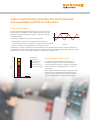
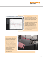
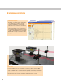
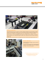
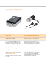
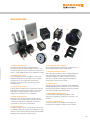
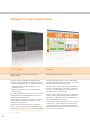
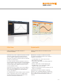
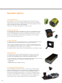
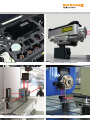
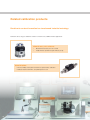
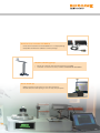
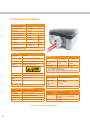
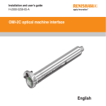
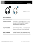
XL-80 laser measurement system Machine tools and CMM The ultimate tool for machine tool and CMM verification to international standards Research and metrology Traceable measurement for calibration and research laboratories Motion systems Unique dynamic performance for high speed, high resolution applications Calibration is the foundation of process control Modern industry has to meet ever tighter tolerances, customer schedules, and the requirements of international quality standards. Together with the pressure to reduce costs, the performance of equipment has never been more important. Measurement and calibration of equipment can help . . . Benefits for equipment manufacturers 2 Benefits for equipment users Test and diagnose machines during manufacture Comply with the ISO 9000 series of standards Build higher accuracy machines Grade machine performance to select the best machine for every job Improve machine design Plan and minimise machine downtime by monitoring wear Reduce machine build cycle times Win high accuracy machining contracts from your competitors Provide a professional maintenance service Improve yield Demonstrate conformance to specification Extend the life of your machine by identifying its sources of errors Laser interferometry provides the most accurate and repeatable method of calibration Laser interferometry The basic principle of using the wavelength of light as a unit of measure has been around since the 1880s. It has been developed since then but it is still based on measuring the interference of light waves, from where it takes the name ‘interferometry’. Wavelength The light wave emerging from a laser has three key properties: • The wavelength is precisely known, allowing accurate measurement • The wavelength is very short, allowing precise or high-resolution measurement • All waves are in-phase, allowing measurement from a known reference Interferometry is a measure of relative movement (measurement from an initial position) rather than an absolute measurement (measurement of a specific position). Different selections of optics pass the laser beam through different paths, allowing a variety of measurement modes (e.g. linear, angular, straightness) to be taken from a single laser unit. 20 Error source Error ppm 18 Altitude (100 m) 16 Air temperature (25° C) 14 Air humidity (70%) 12 Air pressure (970 mbar*) 10 Laser frequency (0.05 ppm) 8 No matter how accurate and stable your laser unit is, the measuring wavelength of the laser can be altered by the environment it passes through. Any change in air temperature, air pressure and relative humidity will induce errors into the measurements. Without reliable and accurate wavelength compensation, linear measurement errors of 20 ppm (parts per million) would be common in typical conditions. These errors can be reduced to 6 4 2 0 Environmental compensation ±0.5 ppm by applying precise environmental compensation. Uncompensated Compensated 3 Introducing the XL-80 laser system PC based software - Simple but powerful software Standard connections USB connection to XL-80 and XC-80 Confidence - The XL system uses interferometry for all its measurement modes (not just linear), giving confidence in the accuracy of all your measurements Cableless optics - Test over full axis travel without suffering the effects of cable drag on the measurement Laser frequency accuracy – ±0.05 ppm (parts per million) over 3 years is achieved by thermal control of the laser tube’s length to within nanometres Convenient to align - Lightweight optics and a comprehensive range of quick fixturing solutions. Patented optics give non-overlapping output and return laser beams to simplify alignment Traceable measurement – Interferometric measurements directly benefit from the traceability of the laser wavelength. Renishaw calibrations are traceable to signatories of the CIPM MRA, which provides consistent measurement standards around the world 4 The key numbers Flexible - Connections for digital quadrature signal outputs (factory option) and remote trigger signal input Thermal stability – The laser heat source remains away from the measurement optics. Anodised aluminium optics also acclimatise 10 times quicker than steel optics, whilst being light and durable Easy to setup – Signal strength LEDs and laser alignment features make it simple to setup and quick to use ±0.5 ppm certified linear measurement accuracy over the full range of environmental operating conditions (±0.5µm per metre) 1 nm linear resolution (even at max. velocity) 4 m/s maximum travel velocity 6 minutes laser preheat time 50 kHz dynamic capture rate 80 m linear range as standard 3 years standard warranty (extendable to 5 years) Portable - The small size and lightweight design of the whole system means it can be transported in a truly portable ‘wheelie-case’, with a linear system and case weighing just 12 kg Accurate - Maintains full measurement accuracy from 0 ºC - 40 ºC (32 ºF - 104 ºF) Ready to use – The XC-80 also comes with remote air and material temperature sensors. The system comes with power supply, a comprehensive user manual and all required cables 5 System applications 25 years of evolution has created our best system ever, offering solutions for a wide range of applications. Machine verification The most common use of the XL-80 laser system is for verification of motion systems. Measuring machine performance allows users to be confident in their machining or identify issues before they are seen in manufactured parts. XL-80 is able to directly measure geometric errors in a machine independently, unlike laser tracker systems. This gives confidence in the measurements and makes it possible to isolate errors. Machine accuracy can then be improved by: • making targeted alterations to the machine’s assembly • using the data to apply error compensation Repeat runs can verify the improvement made and demonstrate the improved capability of the machine. 6 Error compensation Error compensation can improve the overall performance of a machine by reducing the error between the machine’s indicated and actual position. The majority of machine tools contain options to adjust for backlash and linear error. However, more powerful machine controllers offer the option to apply volumetric compensation to the position of the tool tip. Volumetric compensation considers all geometric errors, including linear errors. XL-80 can be used to populate compensation tables. Renishaw Volumetric Compensation software will convert laser measurement readings into a compensation file that can be directly input into specific machine controllers. Specialist laser triggering When using ‘automatic’ capture for linear measurements, the system measures positional errors when the machine has moved to a location and is considered stable. However, some applications require the laser to capture data at custom times or synchronised locations. The following methods of triggering can be achieved with the XL-80 laser system: • manual triggering using a PC mouse or keypress • encoder synchronised triggering* • time based triggering • triggering from the machine’s controller using a relay * requires TB10 trigger box 7 System applications Dynamic analysis Knowledge of a system’s dynamic characteristics – acceleration, velocity, vibration, settle time, resonance and damping – is critical in many applications. These characteristics will influence operational capabilities such as positional accuracy, repeatability, surface finish and wear. The standard XL-80 laser measurement system is capable of capturing dynamic data up to 50 kHz. QuickViewXL is a simple to use, intuitive software package to record, review and save dynamic data. Dual axis In some installations, one axis of a machine is controlled by two drives and two feedback systems (e.g. spar mills, lathes and large gantry type CMMs). In this instance, two laser setups coupled with dual axis software provide the capability to automatically capture data of parallel axes simultaneously. Dual axis measurement software is included as standard with LaserXL software. 8 Laboratory applications The XL-80 has become the choice of system for a variety of laboratory applications since its introduction, including in many of the world’s prestigious calibration houses. Its ultra-stable laser frequency, published error budgets, and unbroken path of traceability from the CIPM MRA* make it easy to understand why it so suited as a reference system. A variety of connections and triggering options make the unit flexible and easy to design into a custom rig. Previous applications have included fixed installation calibration rigs, step gauge measurement and laser frequency calibration rigs. * Renishaw calibrations are traceable to signatories of the CIPM MRA, which provides consistent measurement standards around the world. Special applications Renishaw prides itself in helping its customers make the most of its products. If you have a special requirement for a bespoke product or unique accessory then please contact our knowledgeable sales staff to see how we can help you. For further information about these applications or other potential uses please contact your local Renishaw sales office or visit www.renishaw.com/calibration 9 Key system components XL-80 laser XC-80 compensator and sensors Accurate - an extremely stable laser frequency that is traceable to international standards Reliable - environmental compensator allows XL-80 measurement accuracy over the full environmental range The XL-80 laser has an integrated USB port so there is no requirement for a separate laser-PC interface. The laser also features an auxiliary analogue signal output as standard, with quadrature output as a factory option. The same Aux I/O socket also accepts a trigger signal input for remote triggering. The greatest uncertainty in laser measurements arises from variations in environmental conditions (air temperature, air pressure, and humidity), altering the laser wavelength. The XL-80 laser uses an XC-80 environmental compensation unit and very accurate sensors to automatically compensate measurements for environmental effects. A lightweight, external switched-mode power supply ensures flexible 90 V - 264 V input voltage, whilst maintaining portability. To compensate for a machine’s thermal expansion, up to three material temperature sensors may be connected to the XC-80 compensator. An XL-80 quadrature laser is available by special order only (subject to export control regulations). Please note, XL-80’s with quadrature output should not be used in a feedback system. For laser feedback systems please see www.renishaw.com/laserencoders. The XC-80 features ‘intelligent sensors’ that process the readings at source, offering secure measurements in a compact design. The design of the XC-80 and sensors ensures accurate readings over the full range of operating conditions, from units that are built to withstand daily handling. Magnetic attachments and 5 m sensor cables (that can also be joined together) maximise usability. Renishaw XL-80 lasers are Class 2 lasers requiring no safety goggles. However, users must never stare directly into the beam. 10 Tripod and stage System case Flexible - an adjustable tripod for stable positioning of the laser, with a stage for fine setup adjustment Portable - wheeled system cases offer robust protection for your laser system whilst maximising portability Unless you are using a dedicated measurement rig, you are likely to need a tripod and stage to adjust the laser’s position relative to the measurement axis. Renishaw’s laser system has been designed with portability in mind. The system cases are military specification, injection moulded plastic, with built-in wheels and handles. The cases allow you to protect your valuable system in storage and transport. They feature custom designed foam inserts that minimise shock to the system during impacts and additional pockets for storing fixturing, hardware and accessories. Renishaw offers a choice of carrying cases to complement the size of individual users’ systems. The universal tripod provides a stable base with vertical adjustment. Weighing 3.9 kg and just 64 cm in length (when collapsed) it matches the portability of the rest of the XL-80 laser system. The tripod case can be attached to the system case for easy handling. The XL tripod stage allows for precise angular rotation and translation of the XL-80 laser and is designed to be left attached to the laser unit for easy storage and quick set-up. A ‘quick fit/release’ mechanism enables rapid and secure fixing to the tripod. For those applications where tripod mounting is not convenient, e.g. for mounting directly on a machine tool table, the stage and laser can also be mounted to standard magnetic bases using an optional adapter. Please see the Accessories section on page 15 for more information. 11 Optical setups Linear measurement Angular measurement The linear setup measures positional accuracy along an axis The angular setup measures pitch and yaw errors along an axis The setup measures linear positioning accuracy of an axis by comparing the movement displayed on the machine’s controller with that measured by the laser. The setup provides an accuracy of ±0.5 ppm (parts per million) with a resolution of 1 nanometre. The repeatability of an axis can be measured with multiple tests. Pitch and yaw angular errors are among the largest contributors to machine tool and CMM positioning errors. Even a small error at the spindle can cause a significant effect at the tool tip. This setup can measure maximum angular deflections of up to ±10° with a resolution of 0.01 arc secs. During linear measurement the laser system measures the change in relative distance between a reference and measurement optical path. Either optic can be moving, providing the other optic remains stationary. Angular measurements are made by monitoring the change in optical path generated by the movement of the angular reflector. The angular interferometer is best mounted in a fixed position on a machine. The angular reflector is then mounted to the moving part of the machine. A long range linear kit is available for 40 m - 80 m applications. Please see the Specialist options section on page 18. Linear and angular optics are also available with steel housings for greater thermal stability. For a single setup of both linear and angular optics, contact us to find out more about our special ‘combination optics’ kit. 12 Straightness measurement Rotary axis measurement The straightness setup measures errors in the planes perpendicular to the moving axis The XR20-W rotary axis calibrator and XL-80 laser measure the positional accuracy of a rotary axis Straightness measurements record errors in the horizontal and vertical planes perpendicular to an axis movement. Straightness errors will have a direct effect on the positioning and contouring accuracy of a machine. This could be the result of wear in the guideways, an accident or poor machine foundations. The rotary setup measures rotary axis positioning accuracy by comparing the movement displayed on a machine’s controller with that measured by the hardware. The setup uses an XL-80 laser, XR20-W rotary axis calibrator and an angular interferometer. Straightness measurements are made by monitoring the change in optical path generated by the lateral displacement of the straightness reflector or straightness beam splitter (Wollaston prism). There are kits available for measuring shorter axes (0.1 – 4 m) and longer axes (1 – 30 m). A combination of two straightness measurements make it possible to assess the parallelism of independent axes. The XR20-W provides a compact, lightweight, wireless device for collecting rotary positioning data within ±1 arc second. The XR20-W has been designed to be simple to use, with no operator intervention required during our fastest ever data capture. It provides traceable measurement and can report to international standards using the RotaryXL software package. Accessories are available to allow straightness measurement for vertical axes. Please see Accessories section on page 15. ‘Off axis rotary software’ is available to allow the use of XR20-W in machine configurations where it is difficult to mount the system on the machine’s rotary axis pivot point. • Straightness shutter • Large retroreflector • Straightness base Please see the XR20-W product brochure or www.renishaw.com/calibration for more information on any of the products above. • Beam steerer • Fixed turning mirror • Adjustable turning mirror 13 Optical setups Flatness measurement Squareness measurement The flatness setup measures the surface form for CMMs and all types of surface plate The squareness setup measures the perpendicularity of two nominally orthogonal axes Flatness measurement analyses the form of a surface. This enables a 3D picture to be built up and documents the deviations from a perfectly flat surface. If these errors are significant to the application, then remedial work such as lapping, may be required. Axes need to be square to each other as well as accurate along their length. Squareness errors will have a direct impact on the positional accuracy of parts produced by a machine. These could be the result of movement in machine foundations or misaligned home position sensors on gantry machines. The flatness kit contains two flatness mirrors and three flatness bases to suit the size of the surface. The flatness mirrors not only rotate horizontally, but also tilt vertically. This allows horizontal and vertical adjustment of the laser beam. In addition, angular measurement optics are required for flatness measurements. By using a calibrated optical square and combining two straightness measurements, the squareness between two axes can be calculated. Two standard methods of conducting flatness measurements are supported by the laser software: • Moody method – in which measurement is restricted to eight predefined lines. • Grid method – in which any number of lines may be taken in two orthogonal directions across the surface. 14 To complete a squareness measurement involving the vertical axis, accessories previously mentioned for vertical straightness are required. Other set-up accessories may also be required, depending on the configuration of the application. Your local Renishaw sales office will be able to advise on the best individual solution for you. The Renishaw QC20-W ballbar is also available as a quick diagnosis tool, which includes a squareness assessment. Please see the QC20-W product brochure or www.renishaw.com/calibration for more information. Accessories 2. 5. 8. 10. 7. 9. 4. 6. 1. 3. 1. Optics mounting kit 6. XL magnetic base adaptor The optics mounting kit makes mounting Renishaw measurement optics to a machine simple. The kit is used to mount the measurement optics to the machine under test in a variety of setups. Additional items can be supplied on request. Allows the tripod stage to be mounted to a magnetic base, or any other fixturing which accepts an M8 thread. 2. Straightness base A base designed to mount the straightness reflector and adjustable turning mirror (or laser beam steerer with fixed turning mirror) for some vertical axis measurements. This base can also be used for the mounting of linear and angular optics. 3. Straightness shutter A special shutter assembly allows measurements where the return beam is in the same horizontal plane as the output beam. When used with straightness optics it allows for straightness measurements in the vertical plane. 4. Fixed turning mirror This mirror reflects the laser beam through 90º. Like the swivel mirror, it can be attached to the measurement optics to aid optical set up and is used primarily when there is restricted access to the axis of measurement. 7. LS350 laser beam steerer This unique patented optic provides fine angular adjustment of the laser beam in both horizontal and vertical planes, making laser alignment a simple one step process. The beam steerer speeds up linear, angular and straightness measurements, whether in-line or at 90°. 8. Swivel mirror This mirror can be used as an alignment aid for ANSI B5.54 and ISO 230-6 diagonal measurements. It is also useful when measuring slant-bed lathes. Clamping screws allow the mirror to be easily attached to measurement optics. 9. Adjustable turning mirror Used for directing the beam during straightness and squareness measurements involving the vertical axis of the machine. 10. Large retroreflector Used as a retroreflector for straightness and squareness measurements involving the vertical axis of the machine. 5. Magnetic base Used for mounting the optics or the XL-80 laser (when used in combination with the XL magnetic base adapter). The base features an on/off switch for quick mounting and a female M8 fixing thread. The supplied kit contains 2 bases. 15 Software for laser measurement CARTO suite LaserXL Capture and analyse XL-80 laser system data using database storage Capture XL-80 laser system data for linear axes Introduced in 2015, the CARTO suite, featuring Capture and Explore, provides data capture and analysis for XL-80 measurement. CARTO features a new database system which: LaserXL provides data capture for linear, angular, flatness, straightness and squareness measurements. It also provides time based, dynamic, and dual axis capture. • Automatically stores and organises data for the user, simplifying operation. • Allows users to quickly and easily compare data with historical results. Environmental measurement data is automatically input into LaserXL from the XC-80 kit. It is then used to compensate the laser measurement readings, minimising work for the user and the chance of operator error. The intuitive CARTO user interface allows new users to begin capturing and analysing data quickly, without the need for training or reading lengthy manuals. LaserXL includes a part program generator to rapidly output machine controller code with the specified test parameters. This function is supported for all common controller types. The capacity for customisation throughout the suite means that both Capture and Explore can be tailored to suit an individual user’s requirements. Time based and dynamic measurement Capture features automatic sign detection, reducing the chance of user error, and automated ISO-10360 test setup. Explore brings all the advances made in XCal-View to CARTO. Please check www.renishaw.com/calibration for the latest version of CARTO. 16 LaserXL dynamic measurement facility allows the collection of data at rates of 10 Hz to 50 kHz (at 12 pre-set values) and provides displacement, velocity and acceleration data. These dynamic measurements allow specific machine error characteristics to be quantified. XCal-View QuickviewXL Analyse XL-80 laser system data and report it to international standards Capture and analyse data from an XL-80 laser system in real time XCal-View can be used to comprehensively analyse machine performance and monitor trends over time. This allows the user to diagnose problems quickly and plan machine maintenance. Its intuitive user interface makes it a simple but powerful tool for data analysis. QuickViewXL is the ideal tool for R&D as it provides users with the following functionality for linear, angular or straightness measurements: The software provides automatic reporting that conforms to many international machine performance checking standards, making compliance simple. Standards include ISO, ASME, VDI, JIS and GB/T and an additional Renishaw analysis to concisely summarise results. XCal-View allows users complete control over the display of data. It can overlay multiple data sets on the same screen, select and deselect individual tests, and manipulate the scales to aid comparison. The standard analysis software includes an option to produce generic compensation values for use in a CNC machine controller, improving the machine’s positioning accuracy without the need for physical maintenance. • Live data display in an oscilloscope style format • Data capture rate of 50 kHz • Three modes of data capture: free running, single and multi-shot trigger • Distance, velocity and acceleration display modes • Selectable filters of 1, 2, 5, 10, 20, 50 and 100 ms response to reduce noise in the data. • Manual scale, pan and zoom functions allowing ‘close up’ analysis of selected data Captured data can easily be loaded into supporting applications such as MathCAD, Mathmatica and Microsoft Excel for further analysis using the CSV file format. It can also be loaded into Renishaw’s XCal-View software for reporting. 17 Specialist options Long range linear kit Over long distances a laser beam diverges. Outgoing and incoming laser beams may interfere with one another. The long range linear kit provides a periscope to separate the beams and a large retroreflector to maintain separation. This makes alignment easier and allows for measurements of between 40 m and 80 m. A target is also provided to make alignment as simple as possible. Small linear optics kit The small linear optics kit allows a Renishaw laser system to be used in applications where a small and light measurement retroreflector is desirable. The small retroreflector weighs just 10% of the standard linear retroreflector. This minimises the retroreflector’s effect on a machine’s dynamic performance and provides greater flexibility in its mounting options. The use of these optics limits range to 4 m. Quarter wave plate The quarter wave plate converts laser light from linear to circularly polarised light. It allows the retroreflector optic to be replaced with a plane mirror for linear measurements. There are a range of applications where the use of a plane mirror would be beneficial. Two common applications are high resolution systems or situations where the measurement face moves perpendicularly to the laser beam, e.g. on an XY stage. The application requires a highly reflective surface. Mirrored surfaces are available on request. TB10 trigger box The TB10 monitors the position feedback signals between a machine’s encoder and its controller and then triggers the laser to capture data at user-defined intervals. This synchronises laser data capture with the encoder without stopping the machine. The primary applications of the TB10 are for testing partially built machines and for monitoring encoder errors. The TB10 can be used with the following encoder types: • AquadB: RS422 • Micro-current • 1 Vpp (achieved with two additional resistors) Linear diagonal measurement kit The Linear diagonal measurement kit provides a convenient way to mount and setup a XL-80 laser and measurement optics to a machine tool for checking machine positioning performance along its diagonals in accordance with B5.54 and ISO 230-6 standards. The purpose-built fixturing magnetically attaches to a machine tool bed and provides the user with all the optical adjustments needed to meet the challenges of a diagonal setup. Locating the laser and accessories on a single plate allows the user to quickly move the setup to another location for further testing. Accessories are ordered seperately. 18 XL-80 system case Squareness measurement on a vertical axis XL-80 laser mounted on a magnetic base XL-80 laser with linear/angular combination optics kit What do our customers think? Our laser systems offer the ultimate in confidence and usability. But don’t take our word for it ... The machine designs are no different but we have actually improved the accuracy, cut the support customers need by up to 90%, and have shown customers that we use the latest technology. The key to this improvement is the use of Renishaw’s laser calibration systems which are used to calibrate linear axes on all machine models and calibrate every sub-spindle on CNC lathes. Spinner (Turkey) We have found laser systems to be very reliable, so it is rare that I need to speak to the company on support issues. However, when I do need to get the system calibrated to conform to the requirements of the various standards, the quality and speed of service that Renishaw provides is very important to me. Geo Tec Messtechnik (Germany) 20 Today’s printing companies want a combination of speed, quality and repeatability. They also want to print at large sizes, which makes the other three more difficult to attain. To help us achieve all four, we check all of our printers with a Renishaw XL-80 laser. Inca Digital Printers Ltd (United Kingdom) We’re always looking for ways to do things better. Our performance standard is zero defects, which is the third absolute in our quality philosophy. Nothing leaves this machine shop unless it is exactly right, but we couldn’t do it without Renishaw. FMC Technologies (United Kingdom) 21 About us Our ongoing commitment to service and quality provides our customers with the complete solution Training Renishaw offers an established range of comprehensive operator training courses either on-site or at a Renishaw training centre. Our experience in metrology allows us to teach not just about our products, but also the underlying scientific principles and methods of best practice. This enables our customers to get the most out of their manufacturing process. Certification Renishaw plc is certified and audited regularly to the latest ISO 9001 quality assurance standard. This ensures all aspects of design, manufacture, sales, after sales support, and recalibration remain at the highest standards. The certificate is issued by BSI Management Systems, an internationally recognised certification body, accredited by UKAS. 22 Support Our products enhance quality and productivity, and we strive for total customer satisfaction through superior customer service and expert knowledge of potential product applications. When you purchase a laser or ballbar system from Renishaw you are buying into a worldwide support network that understands machine metrology and the service of production equipment. Renishaw calibrations in the UK are traceable to the National Physical Laboratory, a signatory of the CIPM MRA. Calibration facilities worldwide can provide local laser calibration traceability. Design and build Not only does Renishaw have comprehensive in-house design capability, its extensive manufacturing capacity allows it to produce nearly all components and assemblies in-house. This gives Renishaw the ability to fully understand and control its design and build process. The performance of Renishaw lasers has been independently verified by the National Physical Laboratory (UK) and the Physikalisch-Technische Bundesanstalt (Germany). 23 Related calibration products Renishaw’s constant innovation has transformed industrial metrology. Renishaw offers a range of calibration solutions for machine tools, CMMs and other applications: XR20-W rotary axis calibrator • • Measurement accuracy of ±1 arc second Totally wireless operation for quick and easy set up QC20-W ballbar • The most widely used system for machine tool performance verification • Reduces machine down-time, scrap and inspection costs 24 Renishaw laser encoder with RSU10 • Linear axis measurement for fixed installations in a compact package • Compatible with Renishaw calibration software packages Machine checking gauge • • Monitor the volumetric measurement performance for CMMs Verification of volumetric accuracy to British standard BS EN ISO 10360-2 Axiset Check-Up • Rapid on-machine measurement of rotary axis performance • Accurate detection and reporting of errors in rotary axis pivot points 25 Product specifications System performance Maximum travel velocity 4 m/s* Dynamic capture rate 10 Hz - 50 kHz** Preheat time <6 minutes Specified accuracy range 0 ºC - 40 ºC Environmental sensors Range Accuracy Material temperature 0 ºC - 55 ºC ±0.1 ºC Air temperature 0 ºC - 40 ºC ±0.2 ºC Air pressure 650 mbar - 1150 mbar ±1 mbar Relative humidity (%) 0% - 95% non-condensing ±6% RH * 1.6 m/s (80 nm quadrature); 0.2 m/s (10 nm quadrature) ** 20 MHz in quadrature mode XL-80 laser Laser frequency accuracy ±0.05 ppm Dimensions (weight) 214 mm x 120 mm x 70 mm (1.85 kg) Power supply External, 90 V AC - 264 V AC, auto sensing System measurement capability Linear, angular (and rotary), flatness, straightness and squareness System cases Laser output Case 1 (base system) Case 2 (full system) Case dimensions (L x H x D) 560 mm x 351 mm x 229 mm 560 mm x 455 mm x 265 mm System weight* 12 kg -17 kg 16 kg - 25 kg * System in case weight depends upon options specified Lower weights indicated are for: Case 1: Linear XL and XC system Case 2: Linear, angular and straightness XL and XC system Interface Integral USB comms, no separate interface TPin (trigger signal) Yes Universal tripod Quadrature signal output Yes (factory option) Dimensions folded with boss (weight) Ø160 mm x 640 mm (3.9 kg) Analogue voltage output Yes Signal strength LEDs Yes Working height range (to laser output beam) Minimum: 540 mm Maximum: 1560 mm (column up) Case dimensions 170 mm x 170 mm x 670 mm XC-80 environmental compensator Dimensions (weight) 135 mm x 58 mm x 52 mm (490 g) Warranty and certification Power supply Powered via USB from PC Warranty 3 years (with 5 year option) Internal sensors Air pressure Relative humidity Certification Remote sensors 1 air temperature, 1 - 3 material temperature XL, XC, air and material temperature sensors. Certificates comply with requirements of ISO 17025. Interface Integral USB comms, no separate interface Quality system ISO 9001, BSI certified www.renishaw.com/calibration 26 Linear Specification Metric Linear measurement range* Imperial 0 m – 80 m 0 in – 3200 in Measurement accuracy (with XC-80 compensator) ±0.5 ppm (±0.5µm per metre) Resolution 0.001 µm 0.1 µin * 0 m - 40 m standard. Performance specifications for linear (above) and other measurement modes are quoted to 95% confidence level (k = 2), and are valid across the full environmental operating range. Angular Specification Metric Imperial Axial range 0 m - 15 m 0 in - 590 in Angular measurement range ±175 mm/m ±10º ±0.002A ±0.5 ±0.1M µ rad ±0.002A ±0.1 ±0.007F arc sec ±0.0002A ±0.5 ±0.1M µ rad* ±0.0002A ±0.1 ±0.007F arc sec 0.1 µm/m 0.01 arc sec Angular accuracy Angular accuracy (calibrated) Resolution * for 20° C ±5° C A = displayed angular reading Straightness M = measurement distance in metres Specification Axial range (short range) (long range) Straightness measurement range Accuracy Resolution F = measurement distance in feet Metric Imperial 0.1 m - 4.0 m 4 in - 160 in 1 m - 30 m 40 in - 1200 in ±2.5 mm ±0.1 in (short range) ±0.005A ±0.5 ±0.15 M2 µm ±0.005A ± 20 ±0.5 F2 µin (long range)‡ ±0.025A ±5 ±0.015 M2 µm ±0.025A ±200 ±0.05 F2 µin (short range) 0.01 µm 1 µin (long range) 0.1 µm 10 µin A = displayed straightness reading M = measurement distance in metres; F = measurement distance in feet; ‡ subject to environmental conditions Rotary Specification Metric Imperial Angular target range Measurement accuracy (zero at 0°) up to 25 revolutions ±5 µm/m Max axis rotation speed ±1 arc sec <5˚ axis rotation – unlimited >5˚ axis rotation – 10 rpm Bluetooth range Typically 5 - 10 metres Orientation Flatness Any Specification Metric Imperial Axial range 0 m - 15 m 0 in - 590 in Flatness measurement range Accuracy Resolution Foot spacing ±1.5 mm ±0.06 in ±0.002A ±0.02 M2 µm ±0.002A ±0.08 F2 µin 0.01 µm 1 µin 50 mm, 100 mm and 150 mm 2 in, 4 in and 6 in (approx) A = displayed flatness reading M = length of the diagonal in metres; F = length of the diagonal in feet Squareness Specification Range Accuracy Resolution Metric Imperial ±3/M mm/m ±2000/F arc sec (short range) ±0.005A ±2.5 ±0.8 M µ rad ±0.005A ±0.5 ±0.05 F arc sec (long range) ±0.025A ±2.5 ±0.08 M µ rad ±0.025A ±0.5 ±0.005 F arc sec 0.01 µm/m 0.01 arc sec A = displayed squareness reading M = measurement distance in metres of the longest axis; F = measurement distance in feet 27 Renishaw plc New Mills, Wotton-under-Edge Gloucestershire, GL12 8JR United Kingdom T +44 (0) 1453 524524 F +44 (0) 1453 524901 E [email protected] www.renishaw.com About Renishaw Renishaw is an established world leader in engineering technologies, with a strong history of innovation in product development and manufacturing. Since its formation in 1973, the company has supplied leading-edge products that increase process productivity, improve product quality and deliver cost-effective automation solutions. A worldwide network of subsidiary companies and distributors provides exceptional service and support for its customers. Products include: • Additive manufacturing and vacuum casting technologies for design, prototyping, and production applications • Dental CAD/CAM scanning systems and supply of dental structures • Encoder systems for high-accuracy linear, angle and rotary position feedback • Fixturing for CMMs (co-ordinate measuring machines) and gauging systems • Gauging systems for comparative measurement of machined parts • High-speed laser measurement and surveying systems for use in extreme environments • Laser and ballbar systems for performance measurement and calibration of machines • Medical devices for neurosurgical applications • Probe systems and software for job set-up, tool setting and inspection on CNC machine tools • Raman spectroscopy systems for non-destructive material analysis • Sensor systems and software for measurement on CMMs • Styli for CMM and machine tool probe applications For worldwide contact details, visit www.renishaw.com/contact RENISHAW HAS MADE CONSIDERABLE EFFORTS TO ENSURE THE CONTENT OF THIS DOCUMENT IS CORRECT AT THE DATE OF PUBLICATION BUT MAKES NO WARRANTIES OR REPRESENTATIONS REGARDING THE CONTENT. RENISHAW EXCLUDES LIABILITY, HOWSOEVER ARISING, FOR ANY INACCURACIES IN THIS DOCUMENT. © 2015 Renishaw plc. All rights reserved. Renishaw reserves the right to change specifications without notice. RENISHAW and the probe symbol used in the RENISHAW logo are registered trade marks of Renishaw plc in the United Kingdom and other countries. apply innovation and names and designations of other Renishaw products and technologies are trade marks of Renishaw plc or its subsidiaries. All other brand names and product names used in this document are trade names, trade marks or registered trade marks of their respective owners. *L-9908-1300-01-A Part no: L-9908-1300-01-A Issued: 08.2015