1
IT6100 Series SCPI
High Resolution and High Speed
Programmable Power DC Supply
Models IT6100 Series
IT6121/IT6122/IT6123
IT6151/IT6152/IT6153/IT6154
© Copyright 2005 All Rights Reserved
Ver1.1/MAR, 2008/ IT6100-508
1
Directory
About your safety ............................................................................................................................... 3
Certification and Warranty................................................................................................................. 3
Chapter 1 Remote Operation Mode ................................................................................................. 5
1.1 IT-E131 RS232 Communication Cable .............................................................................. 5
1.2 IT-E132 USB Communication Cable.................................................................................. 5
1.3 IT-E135 GPIB Communication Cable................................................................................. 5
Chapter 2 Communication Order for IT6100 ................................................................................... 7
2.1 IEEE488.2 Common Order ................................................................................................. 7
2.2 SCPI Essential Order........................................................................................................... 7
2.3 Calibration Order.................................................................................................................. 7
2.4 Output Order......................................................................................................................... 8
2.5 Port Configure Order ........................................................................................................... 9
2.6 Trigger Order........................................................................................................................ 9
Chapter 3 SCPI Condition Register.................................................................................................. 9
Chapter 4 SCPI Order Description ................................................................................................. 12
4.1 IEEE488.2 Common Order ............................................................................................... 12
4.2 SCPI Essential Order......................................................................................................... 14
4.3 Output Order....................................................................................................................... 17
4.4 Input measurement order .................................................................................................. 21
4.5Trigger order........................................................................................................................ 23
4.6 Calibration order................................................................................................................. 23
2
About your safety
Pease review the following safety precautions before operating our equipment.
General information
The following safety precautions should be observed before using this product and any
associated instrumentations. Although some instruments and accessories would be used with
non-hazardous voltages, there are situations where hazardous conditions may be present.
This product is intended for use by qualified personnel who recognize shock hazards and are
familiar with the safety precautions required to avoid possible injury. Read and follow all
installation, operation, and maintenance information carefully before using the product. Refer to
this manual for complete product specifications.
If the product is used in a manner not specified, the protection provided by the product may be
impaired. Before performing any maintenance, disconnect the line cord and all test cables.
Protection from electric shock
Operators of this instrument must be protected from electric shock at all times. The responsible
body must ensure that operators are prevented access and/or insulated from every connection
point. In some cases, connections must be exposed to potential human contact. Product
operators in these circumstances must be trained to protect themselves from the risk of electric
shock. If the circuit is capable of operating at or above 1000 volts, no conductive part of the
circuit may be exposed.
Definition of users
Responsible body is the individual or group responsible for the use and maintenance of
equipment is operated within its specifications and operating limits, and for ensuring that
operators are adequately trained.
Operators use the product for its intended function. They must be trained in electrical safety
procedures and proper use of the instrument. They must be protected from electric shock and
contact with hazardous live circuits.
Service is only to be performed by qualified service personnel.
Safety symbols and terms
Connect it to safety earth ground using the wire recommended in the user manual.
The symbol on an instrument indicates that the user should refer to the operating
instructions located in the manual.
High voltage danger
Certification and Warranty
Certification
We certify that this product met its published specifications at time of shipment from the factory.
Warranty
This instrument product is warranted against defects in material and workmanship for a period
of one year from date of delivery. During the warranty period we will, at its option, either repair
or replace products which prove to be defective. For warranty service, with the exception of
warranty options,
this product must be returned to a service facility designated by us. Customer shall prepay
shipping charges by (and shall pay all duty and taxes) for products returned to the supplier for
warranty service.
Except for products returned to customer from another country, supplier shall pay for return of
products to customer.
3
Limitation of Warranty
The foregoing warranty shall not apply to defects resulting from improper or inadequate
maintenance by the Customer, Customer-supplied software or interfacing, unauthorized
modification or misuse, operation outside of the environmental specifications for the product, or
improper site preparation and maintenance.
4
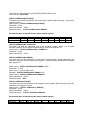
Chapter 1 Remote Operation Mode
The DB9 interface connector on the rear panel of the power supply can be transferred to
RS-232 interface, the following information will tell you how to use the computer to control the
output of the power supply.
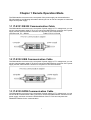
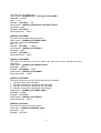
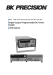
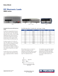
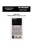
1.1 IT-E131 RS232 Communication Cable
The DB9 interface connector on the rear panel of power supply is TTL voltage level; you can
use the communication cable (IT-E131) to connect the DB9 interface connector of the power
supply and the RS-232 interface connector of computer for the communication.
Computer side TTL→RS232
Cable (IT-E131) PS side
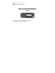
1.2 IT-E132 USB Communication Cable
The DB9 interface connector on the rear panel of power supply is TTL voltage level; you can
use the communication cable (IT-E132) to connect the DB9 interface connector of the power
supply and the USB interface connector of computer for the communication.
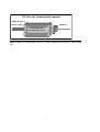
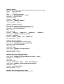
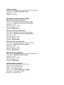
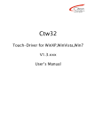
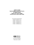
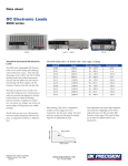
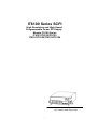
1.3 IT-E135 GPIB Communication Cable
The DB9 interface connector on the rear panel of power supply is TTL voltage level; you can
use the GPIB communication cable (IT-E135) to connect the DB9 interface connector of the
power supply, and then connect the GPIB interface of the IT-E135 and computer with
GPIB/IEEE 488 line for the communication.
5
IT-E135 outer communication adapter
COM interface of
GPIB line
Power supply
IT-E135 ISOLATED
Serial /IEEE 488 Controller
Note: Forbidden to connect DB9 connector in power supply directly with PC or other RS232
port.
6
Chapter 2 Communication Order for IT6100
2.1 IEEE488.2 Common Order
"*CLS"
"*ESE"
"*ESE?"
"*ESR?",
"*IDN?",
"*OPC",
"*OPC?",
"*PSC",
"*PSC?",
"*RST",
"*SRE",
"*SRE?",
"*STB?",
"*TRG",
"*SAV ",
"*RCL",
2.2 SCPI Essential Order
SYSTem
:ERRor[:NEXT]?
:VERSion?,
:ADDRess?
:REMote
:LOCal
:RWLock
STATus
:QUEStionable
[:EVENt]?
:CONDition?
:ENABle <VALUE>
:ENABle?
:OPERation
:EVENt]?
: CONDition?
:ENABle <VALUE>
:ENABle?
2.3 Calibration Order
CALibration
:SECure
[:STATe] {<ON|OFF>,<quoted code>}
]:STATe]?
:VOLTage
:LEVel {<level> }
7
[:DATA] {<numeric value>}
:CURRent
:LEVel {<level> }
[:DATA] {<numeric value>}
:DVM
:LEVel {<level>}
[:DATA] {<numeric value>}
:SAVe
:INITital
2.4 Output Order
OUTPut
[:STATe] {<bool>}
[:STATe]?
:TIMer
[:STATe] {<bool>}
[:STATe]?
:DATA {<timer>}
:DATA?
[SOURce:]
MODE {<FIXed|LIST|DRM>}
MODE?
VOLTage
[:LEVel] {<n>}
[:LEVel]?
:PROTection
:STATe {<bool>}
:STATe?
[:LEVel] {<n>}
[:LEVel]?
CURRent
[:LEVel] {<n>}
[:LEVel]?
LIST
:MODE {<mode>}
:MODE?
:STEP {<step>}
:STEP?
:COUNt {<n>}
:COUNt?
:CURRent
[:LEVel] {<n>,<n>}
[:LEVel]? {<n>}
:VOLTage
[:LEVel] {<n>,<n>}
[:LEVel]? {<n>}
:WIDth {<n>,<n>}
:WIDth? {<n>}
:NAME {<string code>}
:NAME?
:AREA {1|2|4|8}
8
:AREA?
:SAVe {1|2|3|4|5|6|7||8}
:RCL {1|2|3|4|5|6|7|8}
Input Meaaure Order
MEASure
[:SCALar]
:VOLTage[:DC]?
:CURRent[:DC]?
:POWer[:DC]?
:DVM[:DC]?
?
:RESistance[DC]?
2.5 Port Configure Order
[SOURce:]
SYSTem
: SENSe [:STATe] {<bool>}
[:STATe]?
PORT
:MODE {<TRIGger|RIDFi|DIGital>}
:MODE?
RI
:MODE {<OFF|LATChing|LIVE>}
:MODE?
DFI
:SOURce {<OFF|QUES|OPER|ESB|RQS>}
:SOURce?
DIGital
:OUTPut[:STATe] {<bool>}
:INPut[:STATe]?
[:SENSe]
:RESistance:RANGe {LOW | MIDdle | HIGH>}
:RANGe?
2.6 Trigger Order
TRIGger
[:IMMediate]
:SOURce {<source>}
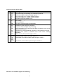
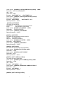
Chapter 3 SCPI Condition Register
You can get the condition of power supply and read parameter from the operation register. The
power supply can get the different state by 4 condition registers. These registers are status byte
register, standard event register, quest condition register and operation status register. The
status byte register stores the information of 3 other register. You can get each register’s
9
meaning from the following table:
BIT
Signal
0
1
2
3
4
CAL
WTG
CV
CC
RI
0
1
2
OV
OT
UNR
0
2
3
OPC
QYE
DDE
4
5
EXE
CME
7
PON
3
5
6
QUES
ESB
MSS
RQS
OPER
7
Meaning
Operation status register
The power supply is calculating new calibration parameter.
The power supply is waiting for trigger signal.
The power supply is in constant voltage condition.
The power supply is in constant current condition.
Show the input level condition of RI
Quest condition register
Over voltage
Over temperature
The output of power supply is unregulated.
Standard event status register
Operation of power supply is completed.
Query error. Data of output array is missing.
Device-dependent error. Data stored in register is missing or error occurs
in preliminary checkout.
Execution error. Order parameter overflows or the condition is not right.
Command error. Syntax or semantic error occurs when receiving
information.
Power on. It is 1when power supply is reset.
Status byte register
If a quest enable condition changes, QUES is 1.
If a standard event status enable register changes, ESB is 1.
If a operation event enable register changes, OPER is 1.
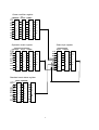
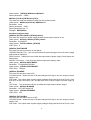
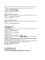
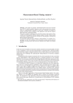
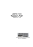
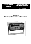
Structure of condition register as following:
10
Quest condition register
condition event enable
OV
OT
Unr
n.u.
n.u.
n.u
n.u
n.u
0
1
2
3
4
5
6
7
0
1
2
3
4
5
6
7
L
O
G
I
C
0
1
2
3
4
5
6
7
O
R
Operation event register
Status byte register
condition event enable
CAL
WTG
CV
CC
RI
n.u
n.u
n.u
0
1
2
3
4
5
6
7
0
1
2
3
4
5
6
7
event enable
n.u
n.u
n.u
QUES
n.u
ESB
RQS
OPER
L
O
G
I
C
0
1
2
3
4
5
6
7
O
R
Standard event status register
event
OPC
n.u
QYE
DDE
EXE
CME
n.u
PON
0
1
2
3
4
5
6
7
enable
0
1
2
3
4
5
6
7
L
O
G
I
C
O
R
11
0
1
2
3
4
5
6
7
0
1
2
3
4
5
6
7
L
O
G
I
C
O
R
Chapter 4 SCPI Order Description
4.1 IEEE488.2 Common Order
*CLS
This order can clean the register as follows:
Standard event status register
Quest condition register
Operation event register
Status byte register
Error code
Order syntax:*CLS
Parameter:None
*ESE
This order can set the parameter of standard event enable register. Setting parameter can
determine which bit value of standard event register is 1 and the byte will enable ESB of
status byte register is 1.
Order syntax:*ESE <NRf>
Parameter:0~255
Reset value:Consult *PSC order
Example:*ESE 128
Quest syntax:*ESE?
?
Return parameter:<NR1>
? *PSC *STB?
?
Reference order:*ESR?
Bit determination of standard event status enable register
Bit position
Bit Name
7
PO
N
128
6
Not used
Bit Weight
PON Power-on
CME Command error
EXE
Execution error
5
CME
4
EXE
3
DDE
32
16
DDE
QYE
OPC
8
2
QYE
1
Not used
0
OPC
4
Device-dependent error
Query error
Operation complete
*ESR?
This order can read the value of standard event status register. After executing this order,
standard event status register is reset. Bit definition of standard event status register is as
the same as the standard event status enable register
Quest syntax:*ESR?
?
Parameter:None
Return parameter:<NR1>
Reference order: *CLS *ESE
*ESE?
? *OPC
*IDN?
12
This order can read information about power supply. The parameter it returns contains 4
segments divided by comma.
Quest syntax:*IDN?
?
Parameter:None
Return parameter:<AARD>
segment
description
ITECH
manufacturer
XXXX
product mode
XXXXXX
product serial number
VX.XX
software version number
For example:ITECH,6152,000004,V1.01
*OPC
When all orders before this order are executed, OPC is 1 of the standard event status
register.
Order syntax:*OPC
Parameter:None
Quest syntax:*OPC?
?
Return parameter:<NR1>
*PSC
This order control if power supply send a query or not when it is reset.
1 OR ON:When power supply is reset, operation event enable register, query event enable
register and standard event status register are all reset.
0 OR OFF:The data of status byte register, operation event enable register, quest event
enable register and standard event status enable register is stored in nonvolatile register,
and is recalled when power supply is reset.
Order syntax:*PSC <bool>
Parameter: 0|1|ON|OFF
?
Quest syntax:*PSC?
Return parameter:0|1
Reference order:*ESE *SRE STAT:OPER:ENAB STAT:QUES:ENAB
*RST
This order reset the power supply to default setting.
CAL:SEC:STAT OFF
OUTP OFF
CURR MAX
VOLT:PROT MAX
VOLT MIN
TRIG:SOUR BUS
SYST:SENS
OFF
PORT:MODE TRIG
RI:MODE OFF
DFI:SOUR OFF
VOLT:PROT:STAT OFF
Order syntax:*RST>
Parameter:None
*SRE
This order can set the parameter of standard event register. Setting parameter can
determine which byte value of status byte register is 1 and the byte will enable RQS of
status byte register is 1. Bit definition of status byte enable register is as the same as the
status byte register.
Order syntax:*SRE <NRf>
Parameter:0~255
13
Reset value:Consult *PSC order
Example:*SRE 128
Quest syntax: *SRE?
?
Return parameter:<NR1>
Reference Order:*ESE *ESR?
? *PSC
*STB?
?
*STB?
This order can read the data from status byte register. After executing this order, status byte
register is reset.
Quest syntax:*STB?
?
Parameter:None
Return parameter:<NR1>
Reference order: *CLS *ESE *ESR
Bit determination of standard event status enable register
Bit Position
Bit Name
Bit Value
7
OPER
128
6
RQS
64
5
ESB
32
4
no use
3
QUES
8
2
no use
1
no use
0
no use
*TRG
When power supply’s trigger source is a order, this order will give a trigger signal. And it’s
function is as the same as the function of [SYSTem:]TRIGger order.
Order syntax:*TRG
Parameter:None
Reference order:TRIG
TRIG:SORU
*SAV
This order can save the parameters of power supply to register. These parameter contains
constant current, constant voltage, maximum voltage value and step voltage value.
Order syntax:*SAV<NRf>
Parameter:1~50
Example:*SAV 3
Reference order:*RCL
*RCL
This order can recall the parameter you saved before from the register.
Order syntax:*RCL<NRf>
Parameter:1~50
Example:*RCL 3
Reference order:*SAV
4.2 SCPI Essential Order
SYSTem:ERRor[:NEXT]?
This order can get the error code and error information of the power supply.
No error
(1)
Too many numeric suffices in Command Spec
(10)
No Input Command to parse
14
(14)
(16)
(17)
(20)
(30)
(40)
(50)
(60)
(65)
(70)
(80)
(90)
(101)
(100)
(110)
Numeric suffix is invalid value
Invalid value in numeric or channel list, e.g. out of range
Invalid number of dimensions in a channel list
Parameter of type Numeric Value overflowed its storage
Wrong units for parameter
Wrong type of parameter(s)
Wrong number of parameters
Unmatched quotation mark (single/double) in parameters
Unmatched bracket
Command keywords were not recognized
No entry in list to retrieve (number list or channel list)
Too many dimensions in entry to be returned in parameters
Command Execution error
Too many command
Rxd error Parity
Error EEPROM
Config data error
Error Calibration data
Factory Data error
Order syntax:SYST:ERR?
Parameter:None
Return parameter:〈NR1〉,〈SRD〉
SYSTem:VERSion?
This order can query the software version.
Order syntax:SYST:VERS?
Parameter:None
Return parameter:<NR2>
SYSTem:ADDRess?
This order can query address of SOURCE METER.
Order syntax:SYST:ADDR?
Parameter:None
Return parameter:<NR2>
SYSTem:REMote
This order can set SOURCE METER as remote control mode.
Order syntax:SYST:REM
Parameter:None
Quest syntax:None
SYSTem:LOCal
This order can set SOURCE METER as panel control mode.
Order syntax:SYST:LOC
Parameter:None
Query syntax:None
SYSTem:RWLock[:STATe]
15
This order can set LOCAL key of SOURCE METER enable or not.
Order syntax:SYST:RWL
STATus:QUEStionable[:EVENt]?
This order can read the parameter from quest event register. After executing , quest event
register is reset.
Quest syntax:STATus:QUEStionable[:EVENt]?
Parameter:None
Return parameter:<NR1>
Reference order: STATus:QUEStionable:ENABle
Bit determination of standard event status enable register
Bit Position
Bit name
Bit Value
7
no use
6
no use
5
no use
4
no use
3
no use
2
unr
4
1
OT
2
0
OV
1
STATus:QUEStionable:CONDition?
This order can read the parameter from quest condition register. When a bit of quest
condition changes, the bit value corresponding in quest event register is 1.
Quest syntax:STATus:QUEStionable: CONDition?
Parameter:None
Return parameter:<NR1>
STATus:QUEStionable:ENABle
This order can set the parameter of quest event enable register. Setting parameter can
determine which bit value of quest event register is 1 and the bit will enable QUES of status
byte register is 1.
Order syntax:STATus:QUEStionable:ENABle <NRf>
Parameter:0~255
Reset value:Consult *PSC order
Example:STATus:QUEStionable:ENABle 128
Quest syntax:STATus:QUEStionable:ENABle?
?
Return parameter:<NR1>
Reference order:*PSC
STATus:OPERation:EVENt]?
This order can read the parameter from operation event register. After executing this order,
operation event register is reset.
Quest syntax:STATus: OPERation [:EVENt]?
Parameter:None
Return parameter:<NR1>
Reference order: STATus: OPERation:ENABle
Bit determination of standard event status enable register
Bit Position
Bit Name
7
no use
6
no use
5
no use
4
RI
16
3
CC
2
CV
1
WTG
0
CAL
Bit value
16
8
4
2
1
STATus:OPERation:CONDition?
This order can read the parameter from the operation condition. When the parameter of
operation condition register changes, the bit corresponding in operation event register is 1.
Quest syntax:STATus: OPERation: CONDition?
Parameter:None
Return parameter:<NR1>
STATus:OPERation:ENABle
This order can set the parameter of operation even enable register. Setting parameter can
determine which bit value of operation event register is 1 and the bit will enable OPER of
status byte register is 1.
Order syntax:STATus: OPERation:ENABle <NRf>
Parameter:0~255
Reset value:Consult *PSC order
Example:STATus: OPERation:ENABle 128
?
Quest syntax:STATus: OPERation:ENABle?
Return parameter:<NR1>
Reference order:*PSC
4.3 Output Order
OUTPut[:STATe]
This order can set power supply output on or off.
Order syntax:OUTPut[:STATe] <bool>
Parameter:0|1|ON|OFF
*RST value:OFF
Quest syntax:OUTPut:STATe?
Return parameter:0|1
OUTPut:TIMer[:STATe]
This order can set output timer’s state of power supply.
Order syntax:OUTPut:TIMer[:STATe] <bool>
Parameter:0|1|ON|OFF
*RST value: OFF
Quest syntax:OUTPut:TIMer:STATe?
Return parameter:0|1
OUTPut:TIMer:DATA
This order can set the time of output timer.
Order syntax:OUTPut:TIMer:DATA <NR1>
Parameter:<NR2>
*RST value:1
Quest syntax:OUPut:TIMer:DATA?
Return parameter:<NR2>
17
[SOURce:]MODE
This order can set the power supply working in order fixed mode or list mode.
FIXed
Order fixed mode
LIST
List mode
DRM
Digital milliohm meter
Order syntax:[SOURce:]MODE <mode>
Parameter:FIXed|LIST|DRM
*RST value: FIXed
Example: MODE FIX
Quest syntax:[SOURce:] MODE?
?
Return parameter:<CRD>
[SOURce:]CURRent [:LEVel]
This order can set current value of power supply.
Order syntax:[SOURce:]CURRent [:LEVel] <NRf>
Parameter:MIN TO MAX|MIN|MAX
Unit:A mA
*RST value: MIN
Example: CURR 3A, CURR 30mA, CURR MAX,
?
Quest syntax:[SOURce:]CURRent [:LEVel]?
Parameter:[MIN|MAX]
?, CURR?
? MAX, CURR?
?MIN
Example:CURR?
Return parameter:<NR2>
CURR MIN
[SOURce:]VOLTage[:LEVel]
This order can set voltage value of power supply.
Order syntax:[SOURce:]VOLTage[:LEVel] <NRf>
Parameter:MIN TO MAX|MIN|MAX
Unit:V | mV| KV
*RST value:MAX
Quest syntax:[SOURce:]VOLTage[:LEVel]?
?
Parameter:[MIN|MAX]
Return parameter:<NR2>
[SOURce:]VOLTage:PROTection:STATe
This order can set over voltage protection.
Order syntax:[SOURce:] VOLTage:PROTection:STATe <bool>
Parameter:0 | 1 | ON | OFF
Unit: None
*RST value:OFF
Example:VOLT:PROT:
:STAT 1,
VOLT :PROT:STAT ON
Quest syntax:[SOURce:] VOLTage:PROTection:STATe?
?
Parameter:None
Example:VOLT:PROT:STAT?
?
Return parameter:<0 | 1>
[SOURce:]VOLTage:PROTection[:LEVel]
This order can set voltage protection maximum level.
18
Order syntax:[SOURce:] VOLTage:PROTection[:LEVel] <NRf>
Parameter:MIN TO MAX|MIN|MAX
Unit:V mV
*RST value:MAX
Example:VOLT:PROT 30V, VOLT PROT MAX
Quest syntax:[SOURce:] VOLTage:PROTection[:LEVel]?
?
Parameter:[MIN|MAX]
Example:VOLT:PROT?
?, VOLT PROT?
? MAX
Return parameter:<NR2>
[SOURce:]LIST:MODE
This order can set list file .
CONTinious
List operation is continuous mode.
STEP
List operation is step mode.
Order syntax:[SOURce:]LIST:MODE <CRD>
Parameter: CONTinious|STEP
Quest syntax:[SOURce:]LIST:MODE?
?
Return parameter:<CRD>
[SOURce:]LIST:STEP
This order can set operation mode of list file.
ONCE
List operate once
REPeat Repeat list operation
Order syntax:[SOURce:]LIST:STEP <SRD>
Parameter: ONCE|REPeat
?
Quest syntax:[SOURce:]LIST:STEP?
Return parameter:<CRD>
[SOURce:]LIST:COUNt
This order can set the steps of list operation.
Order syntax:[SOURce:]LIST:COUNt <NRf>
Parameter:2~400
Quest syntax:[[SOURce:]LIST:COUNt?
?
Parameter:None
Return parameter:<NR1>
[SOURce:]LIST :CURRent[:LEVel]
This order can set current step.
Order syntax:[SOURce:]LIST :CURRent[:LEVel] <NRf>
Parameter:0~30A
Unit:A |mA
Example:LIST:CURR 1,3A;
Quest syntax:[SOURce:]TRANsition:CURRent:TLEVel?
?
Parameter:None
Example:LIST:CURR?
? 1;
Return parameter:<NR2>
[SOURce:]LIST :VOLTage[:LEVel]
19
This order can set voltage step.
Order syntax:[SOURce:]LIST : VOLTage [:LEVel] <NRf>
Parameter:0~360V
Unit:V mV
Example:LIST:VOLT 1,3V;
Quest syntax:[SOURce:]TRANsition: VOLTage:TLEVel?
?
Parameter:None
Example:LIST:VOLT?
? 1;
Return parameter:<NR2>
[SOURce:]LIST:WIDth
This order can set the minimum step time.
Order syntax:[SOURce:]LIST:WIDth <NRf>
Parameter:MIN TO MAX|MIN|MAX
Unit:S mS
Example:LIST:WID 1, 100mS;
Quest syntax:[SOURce:]LIST:WIDth?
?
Parameter:None
Example:LIST:WID? 1;
Return parameter:<NR2>
[SOURce:]LIST:NAME
This order can set name for list file. Make sure that the file name should less than 8
characters.
Order syntax:[SOURce:]LIST:NAME <name>
Parameter:<SRD>
Example:LIST:NAME ‘TEST’;
Quest syntax:[SOURce:]LIST:NAME?
Return parameter:<SRD>
[SOURce:]LIST:AREA
This order can divide the store area of list file with 4 methods.
1.1 group of store area, 400 steps
2.2 groups of store area, each group has 200 steps.
4.4 groups of store area, each group has 100 steps.
8.8 groups of store area, each group has 50 steps.
Order syntax:[SOURce:]LIST:AREA <NR1>
Parameter:1|2|4|8
Example:LIST:AREA 1
Quest syntax:[SOURce:]LIST:AREA?
?
Return parameter:<NR1>
[SOURce:]LIST:SAVe
This order can save list file into register.
Order syntx:[SOURce:]LIST:SAVe <NR1>
Parameter:1~8
Example:LIST:SAV 1
20
[SOURce:]LIST:RCL
This order can recall the list file saved before from the register.
Order syntax:[SOURce:]LIST:SAV <NR1>
Parameter:1~8
Example:LIST:SAV 1
4.4 Input measurement order
MEASure[:SCALar]:VOLTage[:DC]?
This order can get the input voltage of power supply.
Order syntax:MEASure[:SCALar]:VOLTage[:DC]?
Parameter:None
Return parameter:〈NR2〉
Return parameter unit:V
Example:MEAS:VOLT?
?
MEASure[:SCALar]:CURRent[:DC]?
This order can get the input current of power supply.
Order syntax:MEASure[:SCALar]:CURRent[:DC]?
Parameter:None
Return parameter:〈NR2〉
Return parameter unit:A
Example:MEAS:CURR?
?
MEASure[:SCALar]:POWer[:DC]?
This order can get the input power of the power supply.
Order syntax:MEASure[:SCALar]:POWer?
Parameter:None
Return parameter:〈NR2〉
Return parameter unit:W
Example:MEAS:POW?
MEASure[:SCALar]:DVM[:DC]?
This order can get voltage value from the digital voltage meter.
Order syntax:MEASure[:SCALar]:DVM?
Parameter:None
Return parameter:〈NR2〉
Return parameter unit:V
Example:MEAS:DVM?
[:SENSe]:RESistance:RANGe
This order can set the range of milliohm meter.
LOW: 0.01W resistance range
MIDDLE: 0.1W resistance range
HIGH: 1W resistance range
Order syntax:[:SENSe]:RESistance:RANGe
Parameter:LOW | MIDdle | HIGH
Example:RES:RANG LOW
21
Quest syntax:[:SENSe]:RESistance:RANGe?
Return parameter:<SRD>
MEASure[:SCALar]:RESistance[:DC]?
This order can read the resistance value from the milliohm meter.
Order syntax:MEASure[:SCALar]: RESistance?
Parameter:None
Return parameter:〈NR2〉
Return parameter unit:R
Example:MEAS:RES?
Interface Configure Order
[SOURce:]SYSTem:SENSe [:STATe]{<bool>}
This order can control the power supply enable remote sense function or not.
Order syntax:SYSTem: SENSe [:STATe] <bool>
Parameter:0|1|ON|OFF
Quest syntax:SYSTem:SENSe [:STATe]?
?
*RST value:0
[SOURce:]PORT:MODE
This order can set port function of rear panel.:
TRIGGER function: Pin1、pin2 can be used as the external trigger source of power supply
and control list operation.
RI/DFI function:Inhibit Input can control the output state of power supply. Fault Output can
shows false.。
DIGITAL I/O function:It can read and control output port state by order.
Order syntax:SOURce:PORT:MODE
Parameter:TRIGger|RIDFi|DIGital
?
Quest syntax:SOURce:PORT:MODE?
*RST value:TRIGger
[SOURce:]RI:MODE
This order can set input mode of RI.
LITCHING mode:When the level of RI port changes from high to low, the output of power
supply is off.
LIVE node:The output state of power supply changes along with the level of RI port. If the
level of RI is high, the output is on; and the level of RI is low, the output of power supply is
off.
OFF mode: The level state of RI do not affect the output state of power supply.
Order syntax:SOURce:RI:MODE
Parameter:OFF|LATChing|LIVE
Quest syntax:SOURce:RI:MODE?
?
*RST value:OFF
[SOURce:]DFI:SOURce
This order can set output source of DFI.
LITCHING mode:When the level of RI port changes from high to low, the output of power
supply is off.
LIVE node:The output state of power supply changes along with the level of RI port. If the
22
level of RI is high, the output is on; and the level of RI is low, the output of power supply is
off.
OFF mode: The level state of RI do not affect the output state of power supply.
Order syntax:SOURce:DFI:SOURce
Parameter:OFF|QUES|OPER|ESB|RQS
Quest syntax:SOURce:DFI:SOURce?
?
*RST value:OFF
[SOURce:]DIGital:OUTPut[:STATe]
This order can set the output state of port. When the mode of port is DIGITAL, this order is
enable.
Order syntax:SOURce:OUTPut[:STATe]
Paremeter:OFF|ON|0|1
[SOURce:]DIGital:INPut[:STATe]?
This order can set the input state of port. When the mode of port is DIGITAL, this order is
enable.
Order syntax:SOURce:INPut[:STATe] ?
4.5Trigger order
TRIGger[:IMMediate]
When trigger source is order mode, this order will give a trigger signal. And its function is as
the same as *TRG order.
Order syntax:* TRIGger[:IMMediate]
Parameter:None
TRIG:SORU
Reference order:TRIG
TRIGger:SOURce
This order can set the trigger mode of power supply.
IMMediate: If this function is enabled, press Shift + Trigger , the power supply will start
trigger operation once.
EXTernal: External trigger signal (TTL). There is a trigger input port on the rear panel.
When this function is enabled, please give this trigger input port a pulse about 5 mS, and
the power supply will start trigger operation once.
Bus: Order trigger mode. When this function is enabled, and the power supply receives
order*TRG or TRIgger, the power supply will start trigger operation once.
Order syntax:TRIGger:SOURce <mode>
Parameter:IMMediate|EXTernal|BUS
*RST value: KEY
4.6 Calibration order
CALibration:SECure:[STATe]
Set protection mode enable or disable when calibrating the power supply.
Order syntax:CALibration:SECure:[STATe ]{ON|OFF>,[<password>]}
23
Parameter:0|1|ON|OFF, ‘5811
Example:CAL:SEC 1, ‘5811; CAL:SEC OFF
Quest syntax:CALibration:SECure:STATe?
?
Parameter:None
CALibration:VOLTage:LEVel
This order can set voltage calibration point. P1、P2、P3、P4 must be calibrated orderly.
Order syntax:CALibration:VOLTage:LEVel <point>
Parameter:P1|P2
CALibration:VOLTage [:DATA] {<numeric value>}
Return actual output voltage value of calibration point.
Order syntax:CALibration:VOLTage [:DATA] <NRf>
Parameter:<NRf>
Example:CAL:VOLT 30.0002V
CALibration:CURRent:LEVel
This order can set current calibration point. P1、P2、P3、P4 must be calibrated orderly.
Order syntax:CALibration:CURRent:LEVel <point>
Parameter:P1|P2
CALibration:CURRent [:DATA] {<numeric value>}
Return actual output current value to calibration point.
Order syntax:CALibration:CURRent [:DATA] <NRf>
Parameter:<NRf>
Example:CAL:VOLT 3.0002A
CALibration:DVM:LEVel
This order can set current calibration point. P1、P2、P3、P4 must be calibrated orderly.
Order syntax:CALibration:DVM:LEVel <point>
Parameter:P1|P2|P3|P4
CALibration:DVM [:DATA] {<numeric value>}
Return actual output current value to calibration point.
Order syntax:CALibration:DVM [:DATA] <NRf>
Parameter:<NRf>
Example:CAL:VOLT 3.0002A
CALibration:SAVe
This order can save calibration coefficient into nonvolatile register.
Order syntax:CALibration:SAVe
Parameter:None
CALibration: INITial
This order can renew the current calibration coefficient as default.
Order syntax: CALibration: INITial
Parameter: None
24