1
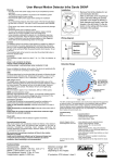
User Manual
160° Wall Mounted HF Detector
Swiss Garde 320 HF UP
Warning!
- Any work on the main power supply must only be completed by trained specialists.
- The product must be installed in accordance with installation guidelines/standards specific to your country.
- Disconnect the 230V power supply before starting the installation
process.
- As a precautionary measure, the power supply of the light should
always be fitted with a (250VAC, 10A) type C fuse in accordance
with EN60898-1.
- Faulty lamps may cause short-circuit and damage the device.
- Disconnect power prior to replacing a lamp.
- To ensure the operational reliability of the detector, keep a minimal
distance of 1m to lamps installed on the same height level.
- Lamps installed underneath the detector or in the detection area may
disturb the functionality. Keep detector away from heating devices.
- In case of malfunction, such as continuous lighting, or false triggering
please refer to the troubleshooting section on page 9.
Function
The high-frequency motion detector actively emits high-frequency, electro-magnetic waves (5.8 GHz) and reacts to changes made by objects
reflecting the waves back. If the detector identifies a change, the light is
switched on and switches off again once the preset time has elapsed
(approx. 8 seconds to 12 minutes). Changes can also be detected
through thin walls, doors and glass
Detection area
As the device is activated by reflections, the range varies depending on
the installation location (i.e. range reduced in an empty factory building).
Transmitting power / electric smog
The transmitting power of the sensor is 1mW, while that of a GSM mobile phone or microwave is 1000 to 2000 times higher.
Installation site
Install the device at a height of approx. 1.1 to 1.5 m above ground. Wire the
detector as follows:
phase/outer conductor (L) brown; neutral/neutral conductor (N) blue;
switching output / switched phase/ outer conductor (L’) red
Optional: remote switching (R) via (supply of the phase) impulse switch
(no neon bulbs!). Device may not be remote switched through phase
interruption. Device operational 1 minute after main connection.
2
Device may be operational without frame for testing purposes
(easier to remove detector head).
Note: Remove voltage before removing detector head.
Connecting electrical loads
High inrush currents will considerably shorten the lifetime of the detector’s in-built relay. Please verify the technical data provided by the lamp
or luminaires manufacturer concerning inrush currents, specifically with
compact fluorescent, fluorescent lamps, electronic ballast, etc. in order
not to overload the internal relay.
We recommend connecting a maximum of three to four motion detectors in parallel. If the number of switching cycles is above average or in
the event of increased (inductive) loads, we recommend using the
short pulse function on the motion detector and switching the load via
an external staircase timer switch or contactor. Keep cables lengths to
a minimum in order to prevent capacitive standby current.
3
Wiring diagrams
Standard installation, optional push button connected to clamp „R“ for
remote detector/lights switching (keep wire short).
Several devices in parallel with additional switch for constant light.
Installation of an RC element, (between neutral conductor (N) and
switched phase L‘) in case of interferences by fluorescent lamps
(switch-off sparks) or by several detectors connected in parallel (caused by capacitive current in the wires). Varistor (between neutral
conductor (N) und phase (L)) to reduce mains voltage peaks.
4
Controls
Caution: Always remove voltage before removing detector head!
SENS (sensitivity/detection range)
Detection range adjustment max = approx. 15 m frontal, 4 m lateral.
Should the detector be too sensitive (triggering without movement in
the detection range), the sensitivity/range can be reduced.
TIME
The timer determines for how long the lights will remain on following the
last movement in the detection area. Min. approx. 8 seconds up to max.
12 minutes.
LUX (twilight sensor)
The twilight sensor regulates the operating threshold (light value) of the
detector determining when the device should be activated. Minimum
value 10 lux (moon symbol): The detector will turn on the light at night.
Maximum value 1000 lux (sun symbol): The detector will turn on the
light during daytime as well.
5
Detection range
top view
frontal detection
SENSITIVE
Detektion frontal
SENSIBEL
6
Troubleshooting
error
light does not turn on:
cause/amendment
- twilight adjustment value too low
- connected lamp defective
- check mains power / fuses
detector triggers without reason - check detection area for potential
reason / light never turns off:
causes of false triggering: draught,
heating, etc. may all provoke faulty
switching!
- detector is too sensitive, reduce the
detec-tion range sensitivity (by remote control or manually) or cover
disturbing segments on the lens by
adhesive tape.
- check distances to lamps (heat reflection or direct light influence)
- connect RC element in parallel to
transformers, relais, electric ballast
light flashes periodically /
detector doesn’t reach
proper working condition:
- non-compensated fluorescent lamps
need an RC element or compensation condenser installed.
triggers or blocks at mains
voltage peaks:
- install a Varistor between phase (L)
and neutral (N) wires
light turns off even if motion
is detected:
- increase the TIME value (to maximum if needed).
turns the light on during
daytime:
- twilight adjustment set too high (set
to a lower value). Respect 1 min.
start-up!
- detector is installed in the shade
- consider changing the location of
detector
After mains connection: the detector takes approx. 1 min. to reach
a stable working condition!
7
Technical data
Nominal power:
Frequency:
Switching power:
Time adjustment:
Twilight switch:
Detection area:
Range:
Installation height:
Dimensions:
Temperature range:
IP protection:
230V / 50Hz
5.8 GHz / 1 mW
2300W / 10A max. (cos φ = 1)
1150VA / 5A max. inductive (cos φ = 0,5)
approx. 8 sec. to 12 min.
10 to 1000 lux
160° horizontal
approx. 1.5 to 15 frontal, 4 m lateral
1.1 to 1.5 m
80 x 80 x 20 mm
-10 to +55 °C
IP 20, class II
Electronic Control
Induction in long installation wires (if several detectors connected in parallel)
may generate a considerable capacitive current on the switched phase. For
electric loads using only a small control current, such as staircase timer
switches, this may lead to permanent switching or general malfunctions. In
order to minimise the capacitive current, an RC element may be connected in
parallel to the load. Alternatively, a contactor, which is more tolerant to
capacitive currents, may be installed before the load. We recommend a
maximum of four detectors connected in parallel.
Do not dispose of electrical appliances in your waste bin, use
the collecting point of your municipality, or return the old device
to your dealer.
8