1
APPLICATION NOTE
SH7268/SH7269 Group
Digital Video Decoder Driver User's Manual
R01AN0779EJ0100
Rev.1.00
Apr 18, 2013
Introduction
This document explains the usage of SH7268/SH7269 Digital Video Decoder (hereafter referred to as ‘VDEC’) Driver.
Target Device
SH7268/SH7269
Contents
1.
Overview ........................................................................................................................................... 2
2.
API..................................................................................................................................................... 5
3.
User-defined Functions ................................................................................................................... 44
4.
Example Usage ............................................................................................................................... 45
R01AN0779EJ0100 Rev.1.00
Apr 18, 2013
Page 1 of 58
APPLICATION NOTE
1.
1.1
Overview
Environment
This program was developed and tested in the following environments.
• CPU
⎯ SH7269
• Development Environment
⎯ HEW (SuperH RISC engine microcomputer software integrated development environment) Version 4.09.00.007
⎯ Renesas SuperH RISC engine Standard Toolchain Version 9.4.1.0
• SH C/C++ Compiler Version 9.04.01
• SH Assembler Version 7.01.02
• SH C/C++ Standard Library Generator Version 3.00.03
• Optimizing Linkage Editor Version 10.01.00
• Evaluation Board
⎯ SH7269 CPU board (Part number: R0K572690C000BR)
⎯ SH7269 VDC4 board (Part number: R0K572690B000BR)
1.2
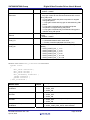
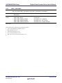
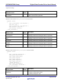
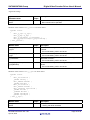
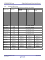
Features
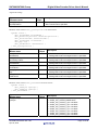
The following table lists the features supported by this driver program.
Table 1 Digital Video Decoder Driver Functions
Item
Input video signal
Sync separation
Burst controlled oscillator (BCO)
Y/C separation
Chroma decoding
Digital clamp
Output adjustment
R01AN0779EJ0100 Rev.1.00
Apr 18, 2013
Function
• Video Signal
Composite video signal (CVBS)
• A/D convertor for video signal input
VIN1 and VIN2 pin input selection
Programmable gain amplifier (PGA)
• Noise reduction LPF
• Auto level control sync slicer
• Horizontal auto frequency control (AFC)
• Vertical count-down
• Interlace detection
• Auto gain control (AGC) / peak limiter control
• Color sub-carrier reproduction
• Color system detection
• NTSC 2D, PAL 2D, SECAM 1D
• Supporting NTSC, PAL and SECAM
• Color killer
• Auto color control (ACC)
• TINT correction, R-Y axis correction
• Pedestal clamp (Y)
• Center clamp (Cb/Cr)
• Noise detection
• Contrast and color adjustment
Page 2 of 58
SH7268/SH7269 Group
1.3
Digital Video Decoder Driver User's Manual
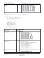
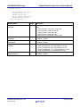
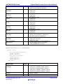
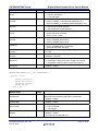
File Configuration
The file configuration of this driver is shown below.
Table 2 File Configuration
File Name
vdec_api.c
vdec_api.h
Description
Source file for VDEC driver functions.
Header file including the prototype declarations for
the VDEC driver calls and definitions of constants.
Source file checking arguments.
Header file for compilation option.
vdec_para.c
vdec_user.h
This driver requires external header files as below.
Table 3 External File Dependencies
File Name
typedefine.h
iodefine.h
1.4
Description
Header file including the typedef declarations for the basic types.
Header file including IO definitions.
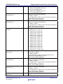
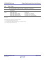
Program Size and Section
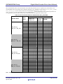
Program size and section used by this driver are shown below.
Table 4 Program Size and Section
"Renesas SuperH RISC engine Standard Toolchain 9.4.1.0"
"Speed & size optimization enabled"
Type
Section name
Size [byte]
Description
ROM
P_VDEC
2.5K (4.2K) Program area
C_VDEC
0 Constant area
D_VDEC
0 Initialized data area
RAM
B_VDEC
0 Uninitialized data area
Note: Program size does not include Input Video Buffer size.
Values in the parentheses are program size when parameter checking is defined.
1.5
Compilation Switches
This driver has compilation switches in vdec_user.h.
1.5.1
Parameter Checking
When _VDEC_PARAMETER_CHECK is defined, the driver checks the arguments of driver functions. Arguments are
checked and error codes are returned if there are errors. For error codes, see 2.2 Error and 2.3 API Function.
R01AN0779EJ0100 Rev.1.00
Apr 18, 2013
Page 3 of 58
SH7268/SH7269 Group
1.6
1.6.1
Digital Video Decoder Driver User's Manual
Restriction
Reserved Word
To separate from the other program, the prefix ‘VDEC’ is appended to the API names, variable names and other
symbols in this driver. Therefore, the names started with ‘VDEC’ (in both uppercase and lowercase letters) should not
be used in the other program.
1.6.2
Dependency
The video decoder output signal which is the result of the decoding is processed as an input signal to the Video Display
Controller 4 (VDC4). When the video decoder output signal is recorded in the memory and/or is displayed on the LCD,
VDC4 driver is required. For VDC4 driver, refer to the Video Display Controller 4 Driver User’s Manual
(R01AN0778EJ).
R01AN0779EJ0100 Rev.1.00
Apr 18, 2013
Page 4 of 58
SH7268/SH7269 Group
2.
Digital Video Decoder Driver User's Manual
API
2.1
2.1.1
Common Definition
Typedef
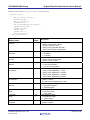
In this driver, data types in Table 5 are used. These declarations are defined in typedefine.h (see 1.3 File Configuration).
Table 5 Typedef Declarations
Typedef
_SBYTE
_UBYTE
_SWORD
_UWORD
_SINT
_UINT
_SDWORD
_UDWORD
_SQWORD
_UQWORD
2.1.2
Type
signed char
unsigned char
signed short
unsigned short
signed int
unsigned int
signed long
unsigned long
signed long long
unsigned long long
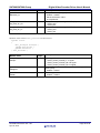
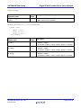
Definition of Enumeration Constants
The vdec_OnOff enumeration defines ON and OFF.
typedef enum {
VDEC_OFF = 0,
VDEC_ON = 1
} vdec_OnOff ;
Enum
VDEC_OFF
VDEC_ON
2.2
Value
0
1
Description
OFF
ON
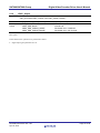
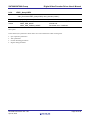
Error
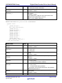
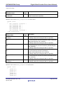
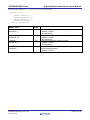
API function calls returns an error code. The error codes are shown in Table 6.
Table 6 Error Code List
Error
VDEC_ERR_NONE
VDEC_ERR_PARAM_RANGE
VDEC_ERR_PARAM_UNDEF
VDEC_ERR_PARAM_INVALID
VDEC_ERR_OTHERS
R01AN0779EJ0100 Rev.1.00
Apr 18, 2013
Value
0
1
2
3
4
Description
Normal end.
Parameter error. Specified value was out of range.
Parameter error. Null should not be specified.
Parameter error. Invalid parameter was specified.
Error. Others.
Page 5 of 58
SH7268/SH7269 Group
2.3
Digital Video Decoder Driver User's Manual
API Function
A list of VDEC driver calls is shown in Table 7.
Table 7 VDEC Driver Calls
Driver Call
Function
VDEC_Initialize
VDEC_Terminate
VDEC_Input
VDEC_SyncSep
VDEC_YcSep
VDEC_ChromaDec
VDEC_DigitalClamp
VDEC_Output
VDEC_QueryVDEC
Video decoder driver initialization
Video decoder driver termination
Video decoder driver input
Video decoder driver sync separation
Video decoder driver y/c separation
Video decoder driver chroma decoding
Video decoder driver digital clamp
Video decoder driver output
Querying Video decoder parameter values
R01AN0779EJ0100 Rev.1.00
Apr 18, 2013
Page 6 of 58
SH7268/SH7269 Group
2.3.1
Syntax
Digital Video Decoder Driver User's Manual
VDEC_Initialize
#include
"vdec_api.h"
vdec_ErrorCode VDEC_Initialize( vdec_VinPin Adc_vinsel
void (*init_func)( _UDWORD ),
_UDWORD user_num ) ;
Parameters •
•
•
Return
•
Values
[in]vdec_VinPin Adc_vinsel
[in]void (*init_func)( _UDWORD )
[in]_UDWORD user_num
vdec_ErrorCode
VDEC_ERR_NONE
VDEC_ERR_PARAM_INVALID
Input pin control
Pointer to the user-defined function
User-defined number
Error code
Normal end.
Parameter error. Invalid parameter.
Description
In this function, the operations are performed as below.
• The specified user-defined function is executed.
• The pin for inputting composite video signals is selected.
Before VDEC driver initialization, user-defined function specified by init_func is called. For information about the
process of user-defined function, see 3.1.
It is not always necessary to specify the user-defined function pointer. If user-defined function is not specified, the
operation stated below should be performed before this VDEC driver initialization.
• Supply the clock to the VDEC.
• Set the environment specific parameters (e.g. related to input video image).
R01AN0779EJ0100 Rev.1.00
Apr 18, 2013
Page 7 of 58
SH7268/SH7269 Group
Digital Video Decoder Driver User's Manual
Arguments Settings
Type
Parameter Name
vdec_VinPin Adc_vinsel
Input /
Output
in
void
(*init_func)( _UDWORD )
in
Description
Input pin control
Composite video signal (CVBS) input pin
• VDEC_VIN_1: VIN1 input
• VDEC_VIN_2: VIN2 input
Pointer to the user-defined function
If ‘0’ is not specified, user-defined function will be called
with an argument specified by user-defined number
(user_num). If necessary, user-defined function must be
implemented by the user.
Syntax
void Init_Func( _UDWORD User_Num ) ;
Parameters
_UDWORD
user_num
R01AN0779EJ0100 Rev.1.00
Apr 18, 2013
in
• [in]_UDWORD
User_Num
• void
User-defined
number
Return
Values
Description
Processing implemented by the user is performed.
User-defined number
This parameter is used as an argument to the userdefined function. This parameter is ignored, when pointer to
the user-defined function (init_func) is set to ‘0’.
Page 8 of 58
SH7268/SH7269 Group
2.3.2
Syntax
Digital Video Decoder Driver User's Manual
VDEC_Terminate
#include
"vdec_api.h"
vdec_ErrorCode VDEC_Terminate( void (*quit_func)( _UDWORD ),
_UDWORD user_num ) ;
Parameters •
•
Return
•
Values
[in]void (*quit_func)( _UDWORD )
[in]_UDWORD user_num
vdec_ErrorCode
VDEC_ERR_NONE
Pointer to the user-defined function
User-defined number
Error code
Normal end.
Description
In this function, the operations are performed as below.
• The specified user-defined function is executed.
After VDEC driver termination, user-defined function specified by quit_func is called. For information about the
process of user-defined function, see 3.2.
It is not always necessary to specify the user-defined function pointer. If user-defined function is not specified, the
operation stated below may be performed after this VDEC driver termination.
• Halt the clock supply to the VDEC.
• Set the environment specific parameters (e.g. related to input video image).
R01AN0779EJ0100 Rev.1.00
Apr 18, 2013
Page 9 of 58
SH7268/SH7269 Group
Digital Video Decoder Driver User's Manual
Arguments Settings
Type
Parameter Name
void
(*quit_func)( _UDWORD )
Input /
Output
in
Description
Pointer to the user-defined function
If ‘0’ is not specified, user-defined function will be called
with an argument specified by user-defined number
(user_num). If necessary, user-defined function must be
implemented by the user.
Syntax
void Quit_Func( _UDWORD User_Num ) ;
Parameters
_UDWORD
user_num
R01AN0779EJ0100 Rev.1.00
Apr 18, 2013
in
• [in]_UDWORD
User_Num
• void
User-defined
number
Return
Values
Description
Processing implemented by the user is performed.
User-defined number
This parameter is used as an argument to the userdefined function. This parameter is ignored, when pointer to
the user-defined function (quit_func) is set to ‘0’.
Page 10 of 58
SH7268/SH7269 Group
2.3.3
Syntax
Digital Video Decoder Driver User's Manual
VDEC_Input
#include
"vdec_api.h"
vdec_ErrorCode VDEC_Input( const vdec_InputSelection *Input ) ;
Parameters • [in]const vdec_InputSelection *Input
Return
• vdec_ErrorCode
VDEC_ERR_NONE
Values
VDEC_ERR_PARAM_UNDEF
VDEC_ERR_PARAM_RANGE
Input selection parameter
Error code
Normal end.
Parameter error. Undefined.
Parameter error. Out of range.
Description
In this function, the operations are performed as below.
• The specified parameters for active image period are set.
The active image period parameters set up in this function are applied only to the Digital Video Decoder module. These
parameters do not correspond to the display size of the input video. To set the display size of the input video, Video
Display Controller 4 module should be used.
Before the settings are reflected, it will take a period of time equal to 1 Vsync period time at the most.
R01AN0779EJ0100 Rev.1.00
Apr 18, 2013
Page 11 of 58
SH7268/SH7269 Group
Digital Video Decoder Driver User's Manual
Arguments Settings
Type
Parameter Name
vdec_InputSelection *
Input
Description
Input /
Output
in
Input selection parameter
Active image period parameter of input video signal
NULL should not be specified.
Members of the structure vdec_InputSelection are shown below.
typedef struct {
_UWORD Srcleft ;
_UWORD Srctop ;
_UWORD Srcheight ;
_UWORD Srcwidth ;
} vdec_InputSelection ;
Type
Member Name
_UWORD
Srcleft
_UWORD
Srctop
_UWORD
Srcheight
_UWORD
Srcwidth
R01AN0779EJ0100 Rev.1.00
Apr 18, 2013
Input/
Output
in
in
in
in
Description
Left end of input video signal capturing area [27MHz
clock cycles]
0x0000 ~ 0x01FF
Top end of input video signal capturing area [lines]
0x0000 ~ 0x003F
Height of input video signal capturing area [lines]
0x0000 ~ 0x03FF
Width of input video signal capturing area [27MHz clock
cycles]
0x0000 ~ 0x07FF
Page 12 of 58
SH7268/SH7269 Group
2.3.4
Syntax
Digital Video Decoder Driver User's Manual
VDEC_SyncSep
#include
"vdec_api.h"
vdec_ErrorCode VDEC_SyncSep( const vdec_SyncSeparation *SyncSeparation ) ;
Parameters • [in]const vdec_SyncSeparation *
SyncSeparation
Return
• vdec_ErrorCode
VDEC_ERR_NONE
Values
VDEC_ERR_PARAM_UNDEF
VDEC_ERR_PARAM_RANGE
VDEC_ERR_PARAM_INVALID
Sync separation parameter
Error code
Normal end.
Parameter error. Undefined.
Parameter error. Out of range.
Parameter error. Invalid parameter.
Description
In this function, the operations are performed as below.
•
•
•
•
•
•
Noise reduction LPF parameters are set.
Auto level control sync slicer parameters are set.
Horizontal AFC parameters are set.
Vertical count-down parameters are set.
AGC / PGA parameters are set.
Peak limiter control parameters are set.
The setting process for the sync separation is performed in this function.
When the AGC is turned off, programmable gain amp (PGA) is set to the manual mode. Before the PGA settings are
reflected, it will take a period of time equal to 1 Vsync period time at the most.
When the AGC is turned off, peak limiter is not operated, though the setting process is performed.
R01AN0779EJ0100 Rev.1.00
Apr 18, 2013
Page 13 of 58
SH7268/SH7269 Group
Digital Video Decoder Driver User's Manual
Arguments Settings
Type
Parameter Name
vdec_SyncSeparation *
SyncSeparation
Description
Input /
Output
in
Sync separation parameter
NULL should not be specified.
Members of the structure vdec_SyncSeparation are shown below.
typedef struct {
vdec_NoiseRdLPF *NoiseRdLPF ;
vdec_AtLvCtrlSyncSlicer *AtLvCtrlSyncSlicer ;
vdec_HorizontalAfc *HorizontalAfc ;
vdec_VcountDown *VcountDown ;
vdec_Agc *Agc ;
vdec_PeakLimCtrl *PeakLimCtrl ;
} vdec_SyncSeparation ;
Type
Member Name
vdec_NoiseRdLPF *
NoiseRdLPF
vdec_AtLvCtrlSyncSlicer *
AtLvCtrlSyncSlicer
vdec_HorizontalAfc *
HorizontalAfc
vdec_VcountDown *
VcountDown
vdec_Agc *
Agc
vdec_PeakLimCtrl *
PeakLimCtrl
Input/
Output
in
in
in
in
in
in
Description
Noise reduction LPF parameter
Settings will be left unchanged if NULL is specified.
Auto level control sync slicer parameter
Settings will be left unchanged if NULL is specified.
Horizontal AFC parameter
Settings will be left unchanged if NULL is specified.
Vertical count-down parameter
Settings will be left unchanged if NULL is specified.
AGC / PGA parameter
Settings will be left unchanged if NULL is specified.
Peak limiter control parameter
Settings will be left unchanged if NULL is specified.
Members of the structure vdec_NoiseRdLPF are shown below.
typedef struct {
vdec_LPFVsync Lpfvsync ;
vdec_LPFHsync Lpfhsync ;
} vdec_NoiseRdLPF ;
Type
Member Name
vdec_LPFVsync
Lpfvsync
R01AN0779EJ0100 Rev.1.00
Apr 18, 2013
Input/
Output
in
Description
LPF cutoff frequency before vertical sync separation
• VDEC_LPF_VSYNC_NONE: None
• VDEC_LPF_VSYNC_0_94: 0.94 MHz
• VDEC_LPF_VSYNC_0_67: 0.67 MHz
• VDEC_LPF_VSYNC_0_54: 0.54 MHz
• VDEC_LPF_VSYNC_0_47: 0.47 MHz
• VDEC_LPF_VSYNC_0_34: 0.34 MHz
• VDEC_LPF_VSYNC_0_27: 0.27 MHz
• VDEC_LPF_VSYNC_0_23: 0.23 MHz
Page 14 of 58
SH7268/SH7269 Group
Digital Video Decoder Driver User's Manual
vdec_LPFHsync
Lpfhsync
in
LPF cutoff frequency before horizontal sync separation
• VDEC_LPF_HSYNC_NONE: None
• VDEC_LPF_HSYNC_2_15: 2.15 MHz
• VDEC_LPF_HSYNC_1_88: 1.88 MHz
• VDEC_LPF_HSYNC_1_34: 1.34 MHz
• VDEC_LPF_HSYNC_1_07: 1.07 MHz
• VDEC_LPF_HSYNC_0_94: 0.94 MHz
• VDEC_LPF_HSYNC_0_67: 0.67 MHz
• VDEC_LPF_HSYNC_0_54: 0.54 MHz
Members of the structure vdec_AtLvCtrlSyncSlicer are shown below.
typedef struct
{
vdec_VelocityShift Velocityshift_H ;
vdec_SliceMode Slicermode_H ;
vdec_SliceMode Slicermode_V ;
_UWORD Syncmaxduty_H ;
_UWORD Syncminduty_H ;
vdec_ClipLv Ssclipsel ;
_UWORD Csyncslice_H ;
_UWORD Syncmaxduty_V ;
_UWORD Syncminduty_V ;
vdec_OnOff Vsyncdelay ;
_UWORD Vsyncslice ;
_UWORD Csyncslice_V ;
} vdec_AtLvCtrlSyncSlicer ;
Type
Member Name
vdec_VelocityShift
Velocityshift_H
Input/
Output
in
vdec_SliceMode
Slicermode_H
in
vdec_SliceMode
Slicermode_V
in
R01AN0779EJ0100 Rev.1.00
Apr 18, 2013
Description
Reference level operation speed control for composite sync
separation
• VDEC_VELOCITY_SHIFT_1: x1
• VDEC_VELOCITY_SHIFT_2: x2
• VDEC_VELOCITY_SHIFT_4: x 4
• VDEC_VELOCITY_SHIFT_8: x 8
• VDEC_VELOCITY_SHIFT_16: x 16
• VDEC_VELOCITY_SHIFT_32: x 32
• VDEC_VELOCITY_SHIFT_64: x 64
• VDEC_VELOCITY_SHIFT_128: x 128
• VDEC_VELOCITY_SHIFT_256: x256
Auto-slice level setting for composite sync separator circuit
(for horizontal sync signal)
• VDEC_SLICE_MODE_MANULAL: Manual setting
• VDEC_SLICE_MODE_AUTO_25:
25% of sync depth (Auto)
• VDEC_SLICE_MODE_AUTO_50:
50% of sync depth (Auto)
• VDEC_SLICE_MODE_AUTO_75:
75% of sync depth (Auto)
Auto-slice level setting for composite sync separation circuit
(for vertical sync signal)
• VDEC_SLICE_MODE_MANULAL: Manual setting
• VDEC_SLICE_MODE_AUTO_25:
Page 15 of 58
SH7268/SH7269 Group
Digital Video Decoder Driver User's Manual
_UWORD
Syncmaxduty_H
in
_UWORD
Syncminduty_H
in
vdec_ClipLv
Ssclipsel
in
_UWORD
Csyncslice_H
in
_UWORD
Syncmaxduty_V
in
_UWORD
Syncminduty_V
in
vdec_OnOff
Vsyncdelay
in
R01AN0779EJ0100 Rev.1.00
Apr 18, 2013
25% of sync depth (Auto)
• VDEC_SLICE_MODE_AUTO_50:
50% of sync depth (Auto)
• VDEC_SLICE_MODE_AUTO_75:
75% of sync depth (Auto)
Max ratio of horizontal cycle to horizontal sync signal pulse
width (for horizontal sync separation)
0x0000 ~ 0x003F
This parameter is valid only when auto slice level setting is
active (Slicemode_H is not set to
VDEC_SLICE_MODE_MANUAL).
Min ratio of horizontal cycle to horizontal sync signal pulse
width (for horizontal sync separation)
0x0000 ~ 0x003F
This parameter is valid only when auto slice level setting is
active (Slicemode_H is not set to
VDEC_SLICE_MODE_MANUAL).
Clipping level
• VDEC_CLIP_LV_512: 512
• VDEC_CLIP_LV_546: 546
• VDEC_CLIP_LV_580: 580
• VDEC_CLIP_LV_614: 614
• VDEC_CLIP_LV_648: 648
• VDEC_CLIP_LV_682: 682
• VDEC_CLIP_LV_716: 716
• VDEC_CLIP_LV_750: 750
• VDEC_CLIP_LV_785: 785
• VDEC_CLIP_LV_819: 819
• VDEC_CLIP_LV_853: 853
• VDEC_CLIP_LV_887: 887
• VDEC_CLIP_LV_921: 921
• VDEC_CLIP_LV_955: 955
• VDEC_CLIP_LV_989: 989
• VDEC_CLIP_LV_1023: 1023
Slice level for composite sync signal separation (for
horizontal sync signal)
0x0000 ~ 0x03FF
This parameter is valid only when manual slice level
setting is active (Slicemode_H is set to
VDEC_SLICE_MODE_MANUAL).
Max ratio of horizontal cycle to horizontal sync signal pulse
width (for vertical sync separation)
0x0000 ~ 0x003F
This parameter is valid only when auto slice level setting is
active (Slicemode_V is not set to
VDEC_SLICE_MODE_MANUAL).
Min ratio of horizontal cycle to horizontal sync signal pulse
width (for vertical sync separation)
0x0000 ~ 0x003F
This parameter is valid only when auto slice level setting is
active (Slicemode_V is not set to
VDEC_SLICE_MODE_MANUAL).
Delays the separated vertical sync signal for 1/4 horizontal
cycle
Page 16 of 58
SH7268/SH7269 Group
_UWORD
Vsyncslice
_UWORD
Csyncslice_V
Digital Video Decoder Driver User's Manual
in
in
• VDEC_OFF: Disable 1/4fH delay
• VDEC_ON: Enable 1/4fH delay
Threshold for vertical sync separation
0x0000 ~ 0x001F
Slice level for composite sync signal separation (for vertical
sync signal)
0x0000 ~ 0x03FF
This parameter is valid only when manual slice level
setting is active (Slicemode_V is set to
VDEC_SLICE_MODE_MANUAL).
Members of the structure vdec_HorizontalAfc are shown below.
typedef struct
{
_UWORD Hafcgain ;
vdec_OnOff Hafcfreerun ;
_UWORD Hafctyp ;
_UWORD Hafcstart ;
_UWORD Nox2Hosc ;
_UWORD Dox2Hosc ;
_UWORD Hafcmax ;
_UWORD Hafcend ;
_UWORD Hafcmode ;
_UWORD Hafcmin ;
_UWORD Phdet_Fix ;
vdec_PhDetDiv Phdet_Div ;
} vdec_HorizontalAfc ;
Type
Member Name
_UWORD
Hafcgain
vdec_OnOff
Hafcfreerun
Input/
Output
in
in
_UWORD
Hafctyp
in
_UWORD
Hafcstart
in
_UWORD
Nox2Hosc
in
_UWORD
Dox2Hosc
in
_UWORD
Hafcmax
in
_UWORD
in
R01AN0779EJ0100 Rev.1.00
Apr 18, 2013
Description
Horizontal AFC loop gain
0x0000 ~ 0x000F
Horizontal AFC free-run oscillation mode ON/OFF
• VDEC_OFF
• VDEC_ON
Horizontal AFC center oscillation frequency [27MHz clock
cycles]
0x0000 ~ 0x03FF
Start line of horizontal AFC normal operation (VBI process
end line)
0x0000 ~ 0x000F
Disable of horizontal AFC double speed detection
• 0: Auto control
• 1: Double speed oscillation disabled
Horizontal AFC forced double-speed oscillation
• 0: Auto control
• 1: Forced double-speed oscillation
In the NTSC, PAL and SECAM formats, this parameter
should always be set to ‘0’.
Maximum oscillation frequency of horizontal AFC [27MHz
clock cycles]
0x0000 ~ 0x03FF
End line of horizontal AFC normal operation (VBI process
Page 17 of 58
SH7268/SH7269 Group
Digital Video Decoder Driver User's Manual
Hafcend
_UWORD
Hafcmode
in
_UWORD
Hafcmin
in
_UWORD
Phdet_Fix
in
vdec_PhDetDiv
Phdet_Div
in
start line)
0x0000 ~ 0x000F
Horizontal AFC VBI period operating mode
Loop gain control for low S/N and horizontal AFC control
during VBI period
• 0: Loop gain is fixed and phase comparison is stopped
during VBI period.
• 1: Loop gain is fixed and loop gain is reduced during VBI
period.
• 2: Loop gain is automatically controlled and phase
comparison is stopped during VBI period.
• 3: Loop gain is automatically controlled and loop gain is
reduced during VBI period.
Min oscillation frequency of horizontal AFC [27MHz clock
cycles]
0x0000 ~ 0x03FF
Forcible or LOWGAIN control
• 0: LOWGAIN determination result used
• 1: Forcibly controlled (adjusted with Phdet_Div)
Phase comparator feedback adjust for low sync signal lock
stability
• VDEC_PHDET_DIV_1_1: 1/1
• VDEC_PHDET_DIV_1_2: 1/2
• VDEC_PHDET_DIV_1_4: 1/4
• VDEC_PHDET_DIV_1_8: 1/8
• VDEC_PHDET_DIV_1_16: 1/16
• VDEC_PHDET_DIV_1_32: 1/32
Members of the structure vdec_VcountDown are shown below.
typedef struct
{
vdec_OnOff Vcdfreerun ;
vdec_OnOff Novcd50 ;
vdec_OnOff Novcd60 ;
vdec_VCntDwFreq Vcddefault ;
_UWORD Vcdwindow ;
_UWORD Vcdoffset ;
} vdec_VcountDown ;
Type
Member Name
vdec_OnOff
Vcdfreerun
Input/
Output
in
vdec_OnOff
Novcd50
in
vdec_OnOff
Novcd60
in
vdec_VCntDwFreq
Vcddefault
in
R01AN0779EJ0100 Rev.1.00
Apr 18, 2013
Description
Vertical countdown free-run oscillation mode ON/OFF
• VDEC_OFF
• VDEC_ON
Vertical countdown 50-Hz oscillation mode
• VDEC_OFF
• VDEC_ON
Vertical countdown 60-Hz (59.94Hz) oscillation mode
• VDEC_OFF
• VDEC_ON
Vertical countdown center oscillation frequency
• VDEC_VCNT_FRQ_AUTO: Auto-detection
Page 18 of 58
SH7268/SH7269 Group
_UWORD
Vcdwindow
_UWORD
Vcdoffset
Digital Video Decoder Driver User's Manual
in
in
• VDEC_VCNT_FRQ_50HZ: 50.00 Hz
• VDEC_VCNT_FRQ_59_94HZ: 59.94 Hz
• VDEC_VCNT_FRQ_60HZ: 60.00 Hz
Vertical countdown sync area [0.1ms]
0x0000 ~ 0x003F
Vertical countdown minimum oscillation frequency
[0.1ms]
0x0000 ~ 0x001F
Members of the structure vdec_Agc are shown below.
typedef struct
{
vdec_OnOff Agcmode ;
_UWORD Doreduce ;
_UWORD Noreduce ;
_UWORD Agcresponse ;
_UWORD Agclevel ;
_UWORD Agcprecis ;
_UWORD Pga_gain ;
} vdec_Agc ;
Type
Member Name
vdec_OnOff Agcmode
Input/
Output
in
_UWORD Doreduce
in
_UWORD Noreduce
in
_UWORD Agcresponse
in
_UWORD Agclevel
in
_UWORD Agcprecis
in
_UWORD Pga_gain
in
Description
A/D converter AGC ON/OFF control & PGA switch
• VDEC_OFF: AGC OFF, PGA manual
• VDEC_ON: AGC ON, automatic
Manual control of sync signal amplitude detection
during VBI period
• 0: Sets sync amplitude to AGC standard value.
• 1: Sets AGC gain to 3/4 times the normal gain value.
Control of sync signal amplitude detection during VBI
period
• 0: Detects sync amplitude.
• 1: Does not detect sync amplitude.
AGC response speed
0x0000 ~ 0x0007
Sync signal reference amplitude
0x0000 ~ 0x01FF
AGC gain adjustment accuracy
0x0000 ~ 0x003F
PGA gain
0x0000 (0.8Vpp) ~ 0x001F (1.6Vpp)
This parameter is valid when Agcmode is set to
VDEC_OFF.
Members of the structure vdec_PeakLimCtrl are shown below.
R01AN0779EJ0100 Rev.1.00
Apr 18, 2013
Page 19 of 58
SH7268/SH7269 Group
Digital Video Decoder Driver User's Manual
typedef struct
{
vdec_PeakLevel Peaklevel ;
_UWORD Peakattack ;
_UWORD Peakrelease ;
vdec_PeakRatio Peakratio ;
_UWORD Maxpeaksamples ;
} vdec_PeakLimCtrl ;
Type
Member Name
vdec_PeakLevel
Peaklevel
Input/
Output
in
_UWORD
Peakattack
_UWORD
Peakrelease
vdec_PeakRatio
Peakratio
in
_UWORD
Maxpeaksamples
in
R01AN0779EJ0100 Rev.1.00
Apr 18, 2013
in
in
Description
Peak luminance value to operate peak limiter (video signal
level)
• VDEC_PEAKLV_LIM_OFF: Limiter OFF
• VDEC_PEAKLV_1008: 1008 LSB
• VDEC_PEAKLV_992: 992 LSB
• VDEC_PEAKLV_960: 960 LSB
Peak limiter is not operated if AGC is OFF.
Response speed with peak limiter gain decreased
0x0000 ~ 0x0003
Response speed with peak limiter gain increased
0x0000 ~ 0x0003
Maximum compression rate of peak limiter
• VDEC_PEAKRATIO_50: Compressed up to 50%
• VDEC_PEAKRATIO_25: Compressed up to 25%
• VDEC_PEAKRATIO_12_5: Compressed up to 12.5%
• VDEC_PEAKRATIO_0: Compressed up to 0%
Allowable number of overflowing pixels [1024 pixels]
0x0000 ~ 0x00FF
Page 20 of 58
SH7268/SH7269 Group
2.3.5
Syntax
Digital Video Decoder Driver User's Manual
VDEC_YcSep
#include
"vdec_api.h"
vdec_ErrorCode VDEC_YcSep( const vdec_YcSeparation *YcSeparation ) ;
Parameters • [in]const vdec_YcSeparation *
YcSeparation
Return
• vdec_ErrorCode
VDEC_ERR_NONE
Values
VDEC_ERR_PARAM_UNDEF
VDEC_ERR_PARAM_RANGE
VDEC_ERR_PARAM_INVALID
Y/C separation parameter
Error code
Normal end.
Parameter error. Undefined.
Parameter error. Out of range.
Parameter error. Invalid parameter.
Description
In this function, the operations are performed as below.
• Y/C separation control parameters are set.
• Chroma filter TAP coefficient parameters for Y/C separation are set.
• Over-range control parameters are set.
R01AN0779EJ0100 Rev.1.00
Apr 18, 2013
Page 21 of 58
SH7268/SH7269 Group
Digital Video Decoder Driver User's Manual
Arguments Settings
Input /
Output
in
Type
Parameter Name
vdec_YcSeparation *
YcSeparation
Description
Y/C separation parameter
NULL should not be specified.
Members of the structure vdec_YcSeparation are shown below.
typedef struct
{
vdec_YcSepCtrl *YcSepCtrl ;
vdec_ChrFilTAP *Wa ;
vdec_ChrFilTAP *Wb ;
vdec_ChrFilTAP *Na ;
vdec_ChrFilTAP *Nb ;
vdec_OverRange *OverRange ;
} vdec_YcSeparation ;
Type
Member Name
vdec_YcSepCtrl *
YcSepCtrl
vdec_ChrFilTAP *
Wa
Input/
Output
in
vdec_ChrFilTAP *
Wb
in
vdec_ChrFilTAP *
Na
in
vdec_ChrFilTAP *
Nb
in
vdec_OverRange *
OverRange
in
in
Description
Y/C separation control parameter
Settings will be left unchanged if NULL is specified.
Chroma filter TAP coefficient parameter for Y/C separation
Two-dimensional cascade broadband (3.58/4.43/SECAMDR)/TAKE-OFF filter TAP coefficient
Settings will be left unchanged if NULL is specified.
Chroma filter TAP coefficient parameter for Y/C separation
Two-dimensional cascade broadband (SECAM-DB) filter
TAP coefficient
Settings will be left unchanged if NULL is specified.
Chroma filter TAP coefficient parameter for Y/C separation
Two-dimensional cascade narrowband
(3.58/4.43/SECAM-DR) filter TAP coefficient
Settings will be left unchanged if NULL is specified.
Chroma filter TAP coefficient parameter for Y/C separation
Two-dimensional cascade narrowband (SECAM-DB) filter
TAP coefficient
Settings will be left unchanged if NULL is specified.
Over-range control parameter
Settings will be left unchanged if NULL is specified.
Members of the structure vdec_YcSepCtrl are shown below.
typedef struct
{
_UWORD K15
_UWORD K13
_UWORD K11
_UWORD K16
_UWORD K14
_UWORD K12
;
;
;
;
;
;
R01AN0779EJ0100 Rev.1.00
Apr 18, 2013
Page 22 of 58
SH7268/SH7269 Group
Digital Video Decoder Driver User's Manual
_UWORD K22A ;
_UWORD K21A ;
_UWORD K22B ;
_UWORD K21B ;
_UWORD K23B ;
_UWORD K23A ;
_UWORD K24 ;
vdec_FilterSel Hbpf_Narrow ;
vdec_FilterSel Hvbpf_Narrow ;
vdec_BpfSel Hbpf1_9Tap_On ;
vdec_BpfSel Hvbpf1_9Tap_On ;
vdec_BpfSel Hfil_Tap_Sel ;
vdec_OnOff Det2_On ;
vdec_FilMixRatio Hsel_Mix_Y ;
vdec_FilMixRatio Vsel_Mix_Y ;
vdec_FilMixRatio Hvsel_Mix_Y ;
_UWORD V_Y_Level ;
vdec_FilMixRatio Det2_Mix_C ;
vdec_FilMixRatio Det2_Mix_Y ;
vdec_FilterModeSel Fil2_Mode_2D ;
vdec_FilterSel Fil2_Narrow_2D ;
} vdec_YcSepCtrl ;
Type
Member Name
_UWORD
K15
_UWORD
K13
_UWORD
K11
_UWORD
K16
_UWORD
K14
_UWORD
K12
_UWORD
K22A
_UWORD
K21A
_UWORD
K22B
_UWORD
K21B
_UWORD
K23B
_UWORD
K23A
_UWORD
K24
vdec_FilterSel
Hbpf_Narrow
R01AN0779EJ0100 Rev.1.00
Apr 18, 2013
Input/
Output
in
in
in
in
in
in
in
in
in
in
in
in
in
in
Description
Two-dimensional Y/C separation filter select coefficient *
0x0000 ~ 0x000F
Two-dimensional Y/C separation filter select coefficient *
0x0000 ~ 0x003F
Two-dimensional Y/C separation filter select coefficient *
0x0000 ~ 0x003F
Two-dimensional Y/C separation filter select coefficient *
0x0000 ~ 0x000F
Two-dimensional Y/C separation filter select coefficient *
0x0000 ~ 0x003F
Two-dimensional Y/C separation filter select coefficient *
0x0000 ~ 0x003F
Two-dimensional Y/C separation filter select coefficient *
0x0000 ~ 0x00FF
Two-dimensional Y/C separation filter select coefficient *
0x0000 ~ 0x003F
Two-dimensional Y/C separation filter select coefficient *
0x0000 ~ 0x00FF
Two-dimensional Y/C separation filter select coefficient *
0x0000 ~ 0x003F
Two-dimensional Y/C separation filter select coefficient *
0x0000 ~ 0x000F
Two-dimensional Y/C separation filter select coefficient *
0x0000 ~ 0x000F
Two-dimensional Y/C separation filter select coefficient *
0x0000 ~ 0x001F
Latter-stage horizontal BPF select
• VDEC_FILSEL_BYPASS: Bypass
• VDEC_FILSEL_17TAP: 17 TAP
Page 23 of 58
SH7268/SH7269 Group
Digital Video Decoder Driver User's Manual
vdec_FilterSel
Hvbpf_Narrow
in
vdec_BpfSel
Hbpf1_9Tap_On
in
vdec_BpfSel
Hvbpf1_9Tap_On
in
vdec_BpfSel
Hfil_Tap_Sel
in
vdec_OnOff
Det2_On
in
vdec_FilMixRatio
Hsel_Mix_Y
in
vdec_FilMixRatio
Vsel_Mix_Y
in
vdec_FilMixRatio
Hvsel_Mix_Y
in
R01AN0779EJ0100 Rev.1.00
Apr 18, 2013
Latter-stage horizontal/vertical BPF select
• VDEC_FILSEL_BYPASS: Bypass
• VDEC_FILSEL_17TAP: 17 TAP
Former-stage horizontal BPF select
• VDEC_BPFSEL_17TAP: 17 TAP
• VDEC_BPFSEL_9TAP: 9 TAP
Former-stage horizontal/vertical BPF select
• VDEC_BPFSEL_17TAP: 17 TAP
• VDEC_BPFSEL_9TAP: 9 TAP
Horizontal filter and horizontal/vertical filter bandwidth switch
signal
• VDEC_BPFSEL_17TAP: 17 TAP
• VDEC_BPFSEL_9TAP: 9 TAP
Two-dimensional filter mixing select
After passing the correlation detection filter, signals are
mixed or not.
• VDEC_OFF: Not mixed
• VDEC_ON: Mixed
Mixing ratio of signal after passing horizontal filter to signal
after passing former-stage horizontal filter
Mixing ratio of signal after passing former-stage horizontal
filter can be specified as follows:
• VDEC_FILMIX_RATIO_0: 0%
• VDEC_FILMIX_RATIO_12_5: 12.5%
• VDEC_FILMIX_RATIO_25: 25%
• VDEC_FILMIX_RATIO_37_5: 37.5%
• VDEC_FILMIX_RATIO_50: 50%
• VDEC_FILMIX_RATIO_62_5: 62.5%
• VDEC_FILMIX_RATIO_75: 75%
• VDEC_FILMIX_RATIO_87_5: 87.5%
• VDEC_FILMIX_RATIO_100: 100%
Mixing ratio of signal after passing vertical filter to signal
after passing former-stage horizontal/vertical filter
Mixing ratio of signal after passing former-stage
horizontal/vertical filter can be specified as follows:
• VDEC_FILMIX_RATIO_0: 0%
• VDEC_FILMIX_RATIO_12_5: 12.5%
• VDEC_FILMIX_RATIO_25: 25%
• VDEC_FILMIX_RATIO_37_5: 37.5%
• VDEC_FILMIX_RATIO_50: 50%
• VDEC_FILMIX_RATIO_62_5: 62.5%
• VDEC_FILMIX_RATIO_75: 75%
• VDEC_FILMIX_RATIO_87_5: 87.5%
• VDEC_FILMIX_RATIO_100: 100%
Mixing ratio of signal after passing horizontal/vertical filter to
signal after passing former-stage horizontal/vertical filter
Mixing ratio of signal after passing former-stage
horizontal/vertical filter can be specified as follows:
• VDEC_FILMIX_RATIO_0: 0%
• VDEC_FILMIX_RATIO_12_5: 12.5%
• VDEC_FILMIX_RATIO_25: 25%
• VDEC_FILMIX_RATIO_37_5: 37.5%
• VDEC_FILMIX_RATIO_50: 50%
Page 24 of 58
SH7268/SH7269 Group
Digital Video Decoder Driver User's Manual
• VDEC_FILMIX_RATIO_62_5: 62.5%
• VDEC_FILMIX_RATIO_75: 75%
• VDEC_FILMIX_RATIO_87_5: 87.5%
• VDEC_FILMIX_RATIO_100: 100%
_UWORD
in
Vertical luminance detection level for correlation detection
filter
V_Y_Level
0x0000 ~ 0x01FF
vdec_FilMixRatio
in
Mixing ratio of C signal after passing horizontal/vertical
adaptive filter to signal after passing correlation detection
Det2_Mix_C
filter
Mixing ratio of signal after passing correlation detection
filter can be specified as follows:
• VDEC_FILMIX_RATIO_0: 0%
• VDEC_FILMIX_RATIO_12_5: 12.5%
• VDEC_FILMIX_RATIO_25: 25%
• VDEC_FILMIX_RATIO_37_5: 37.5%
• VDEC_FILMIX_RATIO_50: 50%
• VDEC_FILMIX_RATIO_62_5: 62.5%
• VDEC_FILMIX_RATIO_75: 75%
• VDEC_FILMIX_RATIO_87_5: 87.5%
• VDEC_FILMIX_RATIO_100: 100%
vdec_FilMixRatio
in
Mixing ratio of C signal for Y generation after passing
horizontal/vertical adaptive filter to signal after passing
Det2_Mix_Y
correlation detection filter
Mixing ratio of signal after passing correlation detection
filter can be specified as follows:
• VDEC_FILMIX_RATIO_0: 0%
• VDEC_FILMIX_RATIO_12_5: 12.5%
• VDEC_FILMIX_RATIO_25: 25%
• VDEC_FILMIX_RATIO_37_5: 37.5%
• VDEC_FILMIX_RATIO_50: 50%
• VDEC_FILMIX_RATIO_62_5: 62.5%
• VDEC_FILMIX_RATIO_75: 75%
• VDEC_FILMIX_RATIO_87_5: 87.5%
• VDEC_FILMIX_RATIO_100: 100%
vdec_FilterModeSel
in
Two-dimensional cascade/TAKE-OFF filter mode select
Fil2_Mode_2D
• VDEC_FILMODE_BYPASS: Bypass
• VDEC_FILMODE_CASCADE: Cascade filter
• VDEC_FILMODE_TAKEOFF: TAKE-OFF filter
vdec_FilterSel
in
Two-dimensional cascade filter select
Fil2_Narrow_2D
• VDEC_FILSEL_BYPASS: Bypass
• VDEC_FILSEL_17TAP: 17 TAP
Note: * For details about two-dimensional Y/C separation filter select coefficient, refer to SH7268 Group,
SH7269 Group User’s Manual: Hardware (R01UH0048EJ).
Members of the structure vdec_ChrFilTAP are shown below. The value VDEC_CHRFIL_TAPCOE_NUM is ‘9’.
typedef struct
{
_UWORD Fil2_2D_F[ VDEC_CHRFIL_TAPCOE_NUM ] ;
} vdec_ChrFilTAP ;
Type
R01AN0779EJ0100 Rev.1.00
Apr 18, 2013
Input/
Description
Page 25 of 58
SH7268/SH7269 Group
Digital Video Decoder Driver User's Manual
Member Name
Output
_UWORD
in
Chroma filter TAP coefficient for Y/C separation
Fil2_2D_F[ VDEC_CHRFIL_TAPCOE_NUM ]
Sign (MSB) + absolute value (0 ~ 4095)
0x0000 ~ 0x0FFF: 0 ~ 4095
0x1000 ~ 0x1FFF: -0 ~ -4095
Members of the structure vdec_OverRange are shown below.
typedef struct
{
_UWORD Radj_O_Level0 ;
_UWORD Radj_U_Level0 ;
_UWORD Radj_O_Level1 ;
_UWORD Radj_U_Level1 ;
_UWORD Radj_O_Level2 ;
_UWORD Radj_U_Level2 ;
_UWORD Test_Moni ;
_UWORD Radj_Mix_K_Fix ;
vdec_OnOff Ucmp_Sw ;
vdec_OnOff Dcmp_Sw ;
vdec_OnOff Hwide_Sw ;
} vdec_OverRange ;
Type
Member Name
_UWORD
Radj_O_Level0
_UWORD
Radj_U_Level0
_UWORD
Radj_O_Level1
_UWORD
Radj_U_Level1
_UWORD
Radj_O_Level2
_UWORD
Radj_U_Level2
_UWORD
Test_Moni
Input/
Output
in
_UWORD
Radj_Mix_K_Fix
in
vdec_OnOff
Ucmp_Sw
in
vdec_OnOff
in
R01AN0779EJ0100 Rev.1.00
Apr 18, 2013
in
in
in
in
in
in
Description
A/D over-threshold level (between levels 0 and 1)
0x0000 ~ 0x03FF
A/D under-threshold level (between levels 2 and 3)
0x0000 ~ 0x03FF
A/D over-threshold level (between levels 1 and 2)
0x0000 ~ 0x03FF
A/D under-threshold level (between levels 2 and 1)
0x0000 ~ 0x03FF
A/D over-threshold level (between levels 2 and 3)
0x0000 ~ 0x03FF
A/D under-threshold level (between levels 1 and 0)
0x0000 ~ 0x03FF
Test mode
• 0 ~ 3: Normal operation
• 4: Level 0 part is output as black
• 5: Level 1 part is output as black
• 6: Level 2 part is output as black
• 7: Level 3 part is output as black
Forced range over/under mode
• 0 ~ 3: Auto detection
• 4: Level 0 (normal state)
• 5: Fixed to level 1 (almost normal)
• 6: Fixed to level 2 (almost over the range)
• 7: Fixed to level 3 (completely over the range)
Over-range detection enable
• VDEC_OFF: Disables over-range detection
• VDEC_ON: Enables over-range detection
Under-range detection enable
Page 26 of 58
SH7268/SH7269 Group
Digital Video Decoder Driver User's Manual
Dcmp_Sw
vdec_OnOff
Hwide_Sw
R01AN0779EJ0100 Rev.1.00
Apr 18, 2013
in
• VDEC_OFF: Disables under-range detection
• VDEC_ON: Enables under -range detection
Horizontal enlargement of over/under-range level
• VDEC_OFF: Does not provide horizontal enlargement
• VDEC_ON: Provides horizontal enlargement
Page 27 of 58
SH7268/SH7269 Group
2.3.6
Syntax
Digital Video Decoder Driver User's Manual
VDEC_ChromaDec
#include
"vdec_api.h"
vdec_ErrorCode VDEC_ChromaDec( const vdec_ChromaDec *ChromaDec ) ;
Parameters • [in]const vdec_ChromaDec *
ChromaDec
Return
• vdec_ErrorCode
VDEC_ERR_NONE
Values
VDEC_ERR_PARAM_UNDEF
VDEC_ERR_PARAM_RANGE
VDEC_ERR_PARAM_INVALID
Chroma decoding parameter
Error code
Normal end.
Parameter error. Undefined.
Parameter error. Out of range.
Parameter error. Invalid parameter.
Description
In this function, the operations are performed as below.
•
•
•
•
•
•
Color system detection parameters are set.
BCO parameters are set.
Color killer parameters are set.
ACC control parameters are set.
TINT / R-Y axis correction parameters are set.
R01AN0779EJ0100 Rev.1.00
Apr 18, 2013
Page 28 of 58
SH7268/SH7269 Group
Digital Video Decoder Driver User's Manual
Arguments Settings
Type
Parameter Name
vdec_ChromaDec *
ChromaDec
Input /
Output
in
Description
Chroma decoding parameter
NULL should not be specified.
Members of the structure vdec_ChromaDec are shown below.
typedef struct
{
vdec_ColorSysDet *ColorSysDet ;
vdec_Bco *Bco ;
vdec_ColorKiller *ColorKiller ;
vdec_AccCtrl *AccCtrl ;
vdec_TintRy *TintRy ;
} vdec_ChromaDec ;
Type
Member Name
vdec_ColorSysDet
*ColorSysDet
vdec_Bco
*Bco
vdec_ColorKiller
*ColorKiller
vdec_AccCtrl
*AccCtrl
vdec_TintRy
*TintRy
Input/
Output
in
in
in
in
in
Description
Color system detection parameter
Settings will be left unchanged if NULL is specified.
BCO parameter
Settings will be left unchanged if NULL is specified.
Color killer parameter
Settings will be left unchanged if NULL is specified.
ACC control parameter
Settings will be left unchanged if NULL is specified.
TINT / R-Y axis correction parameter
Settings will be left unchanged if NULL is specified.
Members of the structure vdec_ColorSysDet are shown below.
typedef struct
{
vdec_ColorSys Defaultsys ;
vdec_OnOff Nontsc358 ;
vdec_OnOff Nontsc443 ;
vdec_OnOff Nopalm ;
vdec_OnOff Nopaln ;
vdec_OnOff Nopal443 ;
vdec_OnOff Nosecam ;
_UWORD Lumadelay ;
vdec_OnOff Chromalpf ;
vdec_DemodMode Demodmode ;
} vdec_ColorSysDet ;
Type
Member Name
vdec_ColorSys
Defaultsys
R01AN0779EJ0100 Rev.1.00
Apr 18, 2013
Input/
Output
in
Description
Default color system
• VDEC_CSYS_NTSC: NTSC
• VDEC_CSYS_PAL: PAL
Page 29 of 58
SH7268/SH7269 Group
Digital Video Decoder Driver User's Manual
vdec_OnOff
Nontsc358
in
vdec_OnOff
Nontsc443
in
vdec_OnOff
Nopalm
in
vdec_OnOff
Nopaln
in
vdec_OnOff
Nopal443
in
vdec_OnOff
Nosecam
in
_UWORD
Lumadelay
in
vdec_OnOff
Chromalpf
in
vdec_DemodMode
Demodmode
in
• VDEC_CSYS_SECAM: SECAM
• VDEC_CSYS_NON: Not specified
NTSC-M detection control
• VDEC_OFF
• VDEC_ON
NTSC-4.43 detection control
• VDEC_OFF
• VDEC_ON
PAL-M detection control
• VDEC_OFF
• VDEC_ON
PAL-N detection control
• VDEC_OFF
• VDEC_ON
PAL-B、G、H、I、D detection control
• VDEC_OFF
• VDEC_ON
SECAM detection control
• VDEC_OFF
• VDEC_ON
Luminance signal delay adjustment
0x0010 (-16) ~ 0x0000 (0) ~ 0x000F (15)
Set a value by the 2s complement.
LPF for demodulated chroma
• VDEC_OFF: Not used
• VDEC_ON: Used
Averaging processing for pre-demodulated line
• VDEC_DEMMD_NO: No processing
• VDEC_DEMMD_PAL: For PAL
Members of the structure vdec_Bco are shown below.
typedef struct
{
vdec_BstLckRange Lockrange ;
_UWORD Loopgain ;
_UWORD Locklimit ;
vdec_OnOff Bcofreerun ;
_UWORD Bgpcheck ;
_UWORD Bgpwidth ;
_UWORD Bgpstart ;
} vdec_Bco ;
Type
Member Name
vdec_BstLckRange
Lockrange
_UWORD
Loopgain
_UWORD
R01AN0779EJ0100 Rev.1.00
Apr 18, 2013
Input/
Output
in
in
in
Description
Burst lock PLL lock range
• VDEC_BST_LCKRNG_400HZ: ±400 Hz
• VDEC_BST_LCKRNG_800HZ: ±800 Hz
• VDEC_BST_LCKRNG_1200HZ: ±1200 Hz
• VDEC_BST_LCKRNG_1600HZ: ±1600 Hz
Burst lock PLL loop gain
0x0000 ~ 0x0003
Level for burst lock PLL to re-search free-run frequency
Page 30 of 58
SH7268/SH7269 Group
Digital Video Decoder Driver User's Manual
Locklimit
vdec_OnOff
Bcofreerun
in
_UWORD
Bgpcheck
in
_UWORD
Bgpwidth
_UWORD
Bgpstart
in
in
0x0000 ~ 0x0003
Burst lock PLL free-run oscillation mode ON/OFF
• VDEC_OFF
• VDEC_ON
Burst gate pulse position check
• 0: Not checked
• 1: Checked
Burst gate pulse width [27MHz clock cycles]
0x0000 ~ 0x007F
Burst gate pulse start position [27MHz clock cycles]
0x0000 ~ 0x00FF
Members of the structure vdec_ColorKiller are shown below.
typedef struct
{
_UWORD Killeroffset ;
vdec_OnOff Killermode ;
_UWORD Killerlevel ;
} vdec_ColorKiller ;
Type
Member Name
_UWORD
Killeroffset
Input/
Output
in
vdec_OnOff
Killermode
in
_UWORD
Killerlevel
in
Description
Color killer offset
0x0000 ~ 0x000F
Killerlevel + Killeroffset is the level to turn off the color
killer.
Forced color killer mode ON/OFF
• VDEC_OFF: Auto-detection
• VDEC_ON: Killer mode is forcedly ON
Color killer operation start point
0x0000 ~ 0x003F
This parameter controls the level to make the killer ON.
Members of the structure vdec_AccCtrl are shown below.
typedef struct
{
_UWORD Accmode ;
vdec_AccMaxGain Accmaxgain ;
_UWORD Acclevel ;
vdec_ChromaSubGain Chromasubgain ;
_UWORD Chromamaingain ;
_UWORD Accresponse ;
_UWORD Accprecis ;
} vdec_AccCtrl ;
Type
Member Name
_UWORD
Accmode
vdec_AccMaxGain
R01AN0779EJ0100 Rev.1.00
Apr 18, 2013
Input/
Output
in
in
Description
ACC operating mode
• 0: Auto gain
• 1: Manual gain
Maximum ACC gain
Page 31 of 58
SH7268/SH7269 Group
Digital Video Decoder Driver User's Manual
•
•
•
•
Accmaxgain
_UWORD
Acclevel
in
vdec_ChromaSubGain
Chromasubgain
in
_UWORD
Chromamaingain
in
_UWORD
Accresponse
_UWORD
Accprecis
in
in
VDEC_ACC_MAXGAIN_6: 6 times
VDEC_ACC_MAXGAIN_8: 8 times
VDEC_ACC_MAXGAIN_12: 12 times
VDEC_ACC_MAXGAIN_16: 16 times
This parameter is valid only when Accmode is set to ‘0’.
ACC reference color burst amplitude
0x0000 ~ 0x01FF
This parameter is valid only when Accmode is set to ‘0’.
Chroma manual gain (sub)
• VDEC_CHR_SUBGAIN_1: 1 time
• VDEC_CHR_SUBGAIN_2: 2 times
• VDEC_CHR_SUBGAIN_4: 4 times
• VDEC_CHR_SUBGAIN_8: 8 times
This parameter is valid only when Accmode is set to ‘1’.
Chroma manual gain (main)
0x0000 ~ 0x01FF
This parameter is valid only when Accmode is set to ‘1’.
The value 0x0100 corresponds to 1 time.
ACC response speed
0x0000 ~ 0x0003
ACC gain adjustment accuracy
0x0000 ~ 0x003F
Members of the structure vdec_TintRy are shown below.
typedef struct
{
_UWORD Tintsub ;
_UWORD Tintmain ;
} vdec_TintRy ;
Type
Member Name
_UWORD
Tintsub
_UWORD
Tintmain
R01AN0779EJ0100 Rev.1.00
Apr 18, 2013
Input/
Output
in
in
Description
Fine adjustment of R-Y demodulation axis [360/1024
degrees]
0x0000 ~ 0x003F
2s complement
This parameter is valid only for NTSC/PAL.
Hue adjustment level [360/1024 degrees]
0x0000 ~ 0x03FF
2s complement
This parameter is valid only for NTSC/PAL.
Page 32 of 58
SH7268/SH7269 Group
2.3.7
Syntax
Digital Video Decoder Driver User's Manual
VDEC_DigitalClamp
#include
"vdec_api.h"
vdec_ErrorCode VDEC_DigitalClamp( const vdec_DigitalClamp *DigitalClamp ) ;
Parameters • [in]const vdec_DigitalClamp
*DigitalClamp
Return
• vdec_ErrorCode
VDEC_ERR_NONE
Values
VDEC_ERR_PARAM_UNDEF
VDEC_ERR_PARAM_RANGE
VDEC_ERR_PARAM_INVALID
Digital clamp parameter
Error code
Normal end.
Parameter error. Undefined.
Parameter error. Out of range.
Parameter error. Invalid parameter.
Description
In this function, the operations are performed as below.
• Pedestal clamp parameters are set.
• Center clamp parameters are set.
• Noise detection parameters are set.
R01AN0779EJ0100 Rev.1.00
Apr 18, 2013
Page 33 of 58
SH7268/SH7269 Group
Digital Video Decoder Driver User's Manual
Arguments Settings
Type
Parameter Name
vdec_DigitalClamp *
DigitalClamp
Input /
Output
in
Description
Digital clamp parameter
NULL should not be specified.
Members of the structure vdec_DigitalClamp are shown below.
typedef struct
{
vdec_PdstlCntrClamp *PdstlCntrClamp ;
vdec_NoiseDet *NoiseDet ;
} vdec_DigitalClamp ;
Type
Member Name
vdec_PdstlCntrClamp *
PdstlCntrClamp
vdec_NoiseDet *
NoiseDet
Input/
Output
in
in
Description
Pedestal/center clamp parameter
Settings will be left unchanged if NULL is specified.
Noise detection parameter
Settings will be left unchanged if NULL is specified.
Members of the structure vdec_PdstlCntrClamp are shown below.
typedef struct
{
_UWORD Dcpresponse ;
_UWORD Dcpstart ;
_UWORD Dcpend ;
_UWORD Dcpwidth ;
vdec_PedestalClamp *PedestalClamp ;
vdec_CenterClamp *CenterClamp ;
} vdec_PdstlCntrClamp ;
Type
Member Name
_UWORD
Dcpresponse
_UWORD
Dcpstart
_UWORD
Dcpend
_UWORD
Dcpwidth
vdec_PedestalClamp *
PedestalClamp
vdec_CenterClamp *
CenterClamp
R01AN0779EJ0100 Rev.1.00
Apr 18, 2013
Input/
Output
in
in
in
in
in
in
Description
Digital clamp response speed
0x0000 ~ 0x0007
Digital clamp start line [lines]
0x0000 ~ 0x003F
Digital clamp end line [lines]
0x0000 ~ 0x003F
Digital clamp pulse width [27MHz clock cycles]
0x0000 ~ 0x007F
Pedestal clamp parameter
Settings will be left unchanged if NULL is specified.
Center clamp parameter
Settings will be left unchanged if NULL is specified.
Page 34 of 58
SH7268/SH7269 Group
Digital Video Decoder Driver User's Manual
Members of the structure vdec_PedestalClamp are shown below.
typedef struct
{
_UWORD Dcpmode_Y ;
_UWORD Dcpcheck ;
_UWORD Dcppos_Y ;
_UWORD Blanklevel_Y ;
vdec_OnOff Clp_Hold_On_Y ;
} vdec_PedestalClamp ;
Type
Member Name
_UWORD
Dcpmode_Y
Input/
Output
in
_UWORD
Dcpcheck
in
_UWORD
Dcppos_Y
in
_UWORD
Blanklevel_Y
in
vdec_OnOff
Clp_Hold_On_Y
in
Description
Clamp level setting mode (Y signal)
• 0: Manual clamp level setting
• 1: Auto clamp level setting
Digital clamp pulse position check
• 0: Not checked
• 1: Checked
Digital clamp pulse horizontal start position (Y signal)
[27MHz clock cycles]
0x0000 ~ 0x00FF
Clamp offset level (Y signal)
0x0000 ~ 0x03FF
Set the subtraction value.
2s complement
Clamp data hold processing ON/OFF (Y)
• VDEC_OFF
• VDEC_ON
Members of the structure vdec_CenterClamp are shown below.
typedef struct
{
_UWORD Dcpmode_C ;
_UWORD Dcppos_C ;
_UWORD Blanklevel_Cb ;
_UWORD Blanklevel_Cr ;
vdec_OnOff Clp_Hold_On_Cb ;
vdec_OnOff Clp_Hold_On_Cr ;
} vdec_CenterClamp ;
Type
Member Name
_UWORD
Dcpmode_C
Input/
Output
in
_UWORD
Dcppos_C
in
_UWORD
Blanklevel_Cb
in
R01AN0779EJ0100 Rev.1.00
Apr 18, 2013
Description
Clamp level setting mode (Cb/Cr signal)
• 0: Manual clamp level setting
• 1: Auto clamp level setting
Digital clamp pulse horizontal start position (Cb/Cr signal)
[27MHz clock cycles]
0x0000 ~ 0x00FF
Clamp offset level (Cb signal)
0x0000 ~ 0x003F
Set the subtraction value.
Page 35 of 58
SH7268/SH7269 Group
Digital Video Decoder Driver User's Manual
_UWORD
Blanklevel_Cr
in
vdec_OnOff
Clp_Hold_On_Cb
in
vdec_OnOff
Clp_Hold_On_Cr
in
2s complement
Clamp offset level (Cr signal)
0x0000 ~ 0x003F
Set the subtraction value.
2s complement
Clamp data hold processing ON/OFF (Cb)
• VDEC_OFF
• VDEC_ON
Clamp data hold processing ON/OFF (Cr)
• VDEC_OFF
• VDEC_ON
Members of the structure vdec_NoiseDet are shown below.
typedef struct
{
vdec_Acfinput Acfinput ;
_UWORD Acflagtime ;
_UWORD Acffilter ;
} vdec_NoiseDet ;
Type
Member Name
vdec_Acfinput
Acfinput
Input/
Output
in
_UWORD
Acflagtime
in
_UWORD
Acffilter
in
R01AN0779EJ0100 Rev.1.00
Apr 18, 2013
Description
Video signal for autocorrelation function
• VDEC_VDSIG_ATCRR_Y: Y signal
• VDEC_VDSIG_ATCRR_CB: Cb signal
• VDEC_VDSIG_ATCRR_CR: Cr signal
Delay time for autocorrelation function calculation [27MHz
clock cycles]
0x0000 ~ 0x001F
Smoothing parameter of autocorrelation function data
0x0000 ~ 0x0003
Page 36 of 58
SH7268/SH7269 Group
2.3.8
Syntax
Digital Video Decoder Driver User's Manual
VDEC_Output
#include
"vdec_api.h"
vdec_ErrorCode VDEC_Output( const vdec_OutAdj *OutAdj ) ;
Parameters • [in]const vdec_OutAdj *OutAdj
Return
• vdec_ErrorCode
VDEC_ERR_NONE
Values
VDEC_ERR_PARAM_UNDEF
VDEC_ERR_PARAM_RANGE
Output adjustment parameter
Error code
Normal end.
Parameter error. Undefined.
Parameter error. Out of range.
Description
In this function, the operations are performed as below.
• Signal output gain parameters are set.
R01AN0779EJ0100 Rev.1.00
Apr 18, 2013
Page 37 of 58
SH7268/SH7269 Group
Digital Video Decoder Driver User's Manual
Arguments Settings
Type
Parameter Name
vdec_OutAdj *
OutAdj
Input /
Output
in
Description
Output adjustment parameter
NULL should not be specified.
Members of the structure vdec_OutAdj are shown below.
typedef struct
{
_UWORD Y_Gain2 ;
_UWORD Cb_Gain2 ;
_UWORD Cr_Gain2 ;
} vdec_OutAdj ;
Type
Member Name
_UWORD
Y_Gain2
Input/
Output
in
_UWORD
Cb_Gain2
in
_UWORD
Cr_Gain2
in
R01AN0779EJ0100 Rev.1.00
Apr 18, 2013
Description
Y signal gain coefficient
0x0000 ~ 0x03FF
(0: 0 times, 0x0200: 1.0 time, 0x03FF: Approx. 2.0 times)
Cb signal gain coefficient
0x0000 ~ 0x03FF
(0: 0 times, 0x0200: 1.0 time, 0x03FF: Approx. 2.0 times)
Cr signal gain coefficient
0x0000 ~ 0x03FF
(0: 0 times, 0x0200: 1.0 time, 0x03FF: Approx. 2.0 times)
Page 38 of 58
SH7268/SH7269 Group
2.3.9
Syntax
Digital Video Decoder Driver User's Manual
VDEC_QueryVDEC
#include
"vdec_api.h"
vdec_ErrorCode VDEC_QueryVDEC( vdec_Queries *param ) ;
Parameters • [out]vdec_Queries *param
Return
• vdec_ErrorCode
VDEC_ERR_NONE
Values
VDEC_ERR_PARAM_UNDEF
Pointer to the result of the query
Error code
Normal end.
Parameter error. Undefined.
Description
In this function, the parameters shown below are retrieved from the VDEC read registers.
•
•
•
•
Sync separation parameters
AGC parameters
Chroma decoding parameters
Digital clamp parameters
R01AN0779EJ0100 Rev.1.00
Apr 18, 2013
Page 39 of 58
SH7268/SH7269 Group
Digital Video Decoder Driver User's Manual
Arguments Settings
Type
Parameter Name
vdec_Queries *
param
Input /
Output
out
Description
Pointer to the result of the query
NULL should not be specified.
Members of the structure vdec_Queries are shown below.
typedef struct
{
vdec_Q_Sync *q_Sync ;
vdec_Q_Agc *q_Agc ;
vdec_Q_ChromaDec *q_ChromaDec ;
vdec_Q_DigitalClamp *q_DigitalClamp ;
} vdec_Queries ;
Type
Member Name
vdec_Q_Sync *
q_Sync
Input/
Output
out
vdec_Q_Agc *
q_Agc
vdec_Q_ChromaDec *
q_ChromaDec
out
vdec_Q_DigitalClamp *
q_DigitalClamp
out
out
Description
Pointer to the memory where the sync separation parameter
is stored.
If it is unnecessary, NULL can be set.
Pointer to the memory where the AGC parameter is stored.
If it is unnecessary, NULL can be set.
Pointer to the memory where the chroma decoding
parameter is stored.
If it is unnecessary, NULL can be set.
Pointer to the memory where the digital clamp parameter is
stored.
If it is unnecessary, NULL can be set.
Members of the structure vdec_Q_Sync are shown below.
typedef struct
{
vdec_Lock Fhlock ;
_UWORD Isnoisy ;
vdec_FhMode Fhmode ;
_UWORD Nosignal ;
vdec_Lock Fvlock ;
vdec_FvMode Fvmode ;
vdec_InterDet Interlaced ;
_UWORD Fvcount ;
_UDWORD Fhcount ;
_UWORD Isreduced ;
_UWORD Syncdepth ;
} vdec_Q_Sync ;
Type
Member Name
vdec_Lock
Fhlock
R01AN0779EJ0100 Rev.1.00
Apr 18, 2013
Input/
Output
out
Description
Horizontal AFC lock detection result
• VDEC_UNLOCK: Unlocked
Page 40 of 58
SH7268/SH7269 Group
Digital Video Decoder Driver User's Manual
_UWORD
Isnoisy
out
vdec_FhMode
Fhmode
out
_UWORD
Nosignal
out
vdec_Lock
Fvlock
out
vdec_FvMode
Fvmode
out
vdec_InterDet
Interlaced
out
_UWORD
Fvcount
_UDWORD
Fhcount
_UWORD
Isreduced
out
_UWORD
Syncdepth
out
out
out
• VDEC_LOCK: Locked
Detection result of low S/N signal by sync separation
• 0: Not low S/N signal
• 1: Low S/N signal
Speed detection result
• VDEC_FHMODE_I: Normal speed (525i/625i, etc.)
• VDEC_FHMODE_P: Multiplied speed (525p/625p, etc.)
No-signal detection result
• 0: Vertical sync signal detected
• 1: No vertical sync signal detected
Vertical countdown lock detection result
• VDEC_UNLOCK: Unlocked
• VDEC_LOCK: Locked
Vertical countdown oscillation mode
• VDEC_FVMODE_50HZ: 50Hz
• VDEC_FVMODE_60HZ: 60Hz
Interlace detection result
• VDEC_PROGRESSIVE: Progressive
• VDEC_INTERLACE: Interlace
Vertical cycle measurement result [0.1ms]
0 ~ 255
Horizontal AFC oscillation cycle [1/64 of 27MHz clock cycle]
0x00000 ~ 0x1FFFF
Sync amplitude detection result during VBI period
• 0: Amplitude is larger than that in image active period.
• 1: Amplitude is equal to that in image active period.
Sync pulse amplitude detection result
0x0000 ~ 0x03FF
Members of the structure vdec_Q_Agc are shown below.
typedef struct
{
_UWORD Highsamples ;
_UWORD Peaksamples ;
_UWORD Agcconverge ;
_UWORD Agcgain ;
} vdec_Q_Agc ;
Type
Member Name
_UWORD
Highsamples
Input/
Output
out
_UWORD
Peaksamples
_UWORD
Agcconverge
out
_UWORD
Agcgain
out
R01AN0779EJ0100 Rev.1.00
Apr 18, 2013
out
Description
Number of pixels which have larger luminance value than
peak luminance limited by peak limiter [1024pixels]
0x0000 ~ 0x00FF
Number of overflowing pixels [1024pixels]
0x0000 ~ 0x00FF
AGC convergence detection result
• 0: Not converged
• 1: Converged
Current AGC gain value
0x0000 ~ 0x00FF
The value 64 corresponds to x1.
Page 41 of 58
SH7268/SH7269 Group
Digital Video Decoder Driver User's Manual
Members of the structure vdec_Q_ChromaDec are shown below.
typedef struct
{
vdec_ColorSys Colorsys ;
_UWORD Fscmode ;
vdec_Lock Fsclock ;
_UWORD Noburst ;
vdec_ChromaSubGain Accsubgain ;
_UWORD Accmaingain ;
_UWORD Issecam ;
_UWORD Ispal ;
_UWORD Isntsc ;
_UWORD Locklevel ;
} vdec_Q_ChromaDec ;
Type
Member Name
vdec_ColorSys
Colorsys
Input/
Output
out
_UWORD
Fscmode
out
vdec_Lock
Fsclock
out
_UWORD
Noburst
out
vdec_ChromaSubGain
Accsubgain
out
_UWORD
Accmaingain
out
_UWORD
Issecam
out
_UWORD
Ispal
out
_UWORD
Isntsc
out
_UWORD
Locklevel
out
R01AN0779EJ0100 Rev.1.00
Apr 18, 2013
Description
Color system detection result
• VDEC_CSYS_NTSC: NTSC
• VDEC_CSYS_PAL: PAL
• VDEC_CSYS_SECAM: SECAM
• VDEC_CSYS_NON: Undetectable
Color sub-carrier frequency detection result
• 0: 3.58MHz
• 1: 4.43MHz
Burst lock PLL lock state detection result
• VDEC_UNLOCK: Unlocked
• VDEC_LOCK: Locked
Color burst detection result
• 0: Color burst present
• 1: No color burst present
Current ACC gain value (sub)
• VDEC_CHR_SUBGAIN_1: 1 time
• VDEC_CHR_SUBGAIN_2: 2 times
• VDEC_CHR_SUBGAIN_4: 4 times
• VDEC_CHR_SUBGAIN_8: 8 times
Current ACC gain value (main)
0x0000 ~ 0x01FF
The value 256 corresponds to 1 time.
SECAM detection result
• 0: Not SECAM signal
• 1: SECAM signal
PAL detection result
• 0: Not PAL signal
• 1: PAL signal
NTSC detection result
• 0: Not NTSC signal
• 1: NTSC signal
Low S/N signal detection result by burst lock PLL
0x0000 ~ 0x00FF
Page 42 of 58
SH7268/SH7269 Group
Digital Video Decoder Driver User's Manual
Members of the structure vdec_Q_DigitalClamp are shown below.
typedef struct
{
_UWORD Clamplevel_Y ;
_UWORD Clamplevel_Cb ;
_UWORD Clamplevel_Cr ;
_UWORD Acfstrength ;
} vdec_Q_DigitalClamp ;
Type
Member Name
_UWORD
Clamplevel_Y
Input/
Output
out
_UWORD
Clamplevel_Cb
out
_UWORD
Clamplevel_Cr
out
_UWORD
Acfstrength
out
R01AN0779EJ0100 Rev.1.00
Apr 18, 2013
Description
Digital clamp subtraction value (Y signal)
0x0000 ~ 0x03FF
2s complement
Digital clamp subtraction value (Cb signal)
0x0000 ~ 0x003F
2s complement
Digital clamp subtraction value (Cr signal)
0x0000 ~ 0x003F
2s complement
Noise autocorrelation strength at digital clamp pulse position
(normal pedestal position)
0x0000 ~ 0xFFFF
Page 43 of 58
SH7268/SH7269 Group
3.
Digital Video Decoder Driver User's Manual
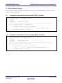
User-defined Functions
Driver calls VDEC_Initialize and VDEC_Terminate allow execution of user-defined functions. Examples of the userdefined function are shown below.
3.1
Example of User-defined Function within VDEC_Initialize
1 /******************************************************************//**
2
* Function Name : Init_VDEC_CallBack
3
* @brief
4
* @param
[in]_UDWORD mode
5
* @retval
void
6
*********************************************************************/
7 void Init_VDEC_CallBack( _UDWORD mode )
8 {
9
/* standby control register 10 (STBCR10)
10
b7
0------- ; MSTP107 : 0 : Video Decoder enable */
11
CPG.STBCR10.BYTE &= ~0x80u ;
12
}
3.2
Example of User-defined Function within VDEC_Terminate
1 /******************************************************************//**
2
* Function Name : Quit_VDEC_CallBack
3
* @brief
4
* @param
[in]_UDWORD mode
5
* @retval
void
6
*********************************************************************/
7 void Quit_VDEC_CallBack( _UDWORD mode )
8 {
9
/* standby control register 10 (STBCR10)
10
b7
1------- ; MSTP107 : Video Decoder disable */
11
CPG.STBCR10.BYTE |= 0x80u ;
12
}
R01AN0779EJ0100 Rev.1.00
Apr 18, 2013
Page 44 of 58
SH7268/SH7269 Group
4.
Digital Video Decoder Driver User's Manual
Example Usage
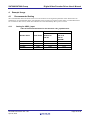
4.1
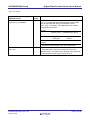
Recommended Setting
The recommended values and initial values set in the structures as the argument parameter of the API function are
stated below. If recommended values of all members in the structures are equal to initial values, recommended values
are not stated. In this section, initial value indicates the value immediately after a power-on reset.
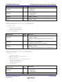
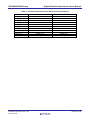
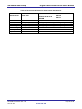
4.1.1
Setting for VDEC_Input
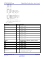
Table 8 Recommended Value for the Structure vdec_InputSelection
Member Name
Srcleft
Srctop
Srcheight
Srcwidth
R01AN0779EJ0100 Rev.1.00
Apr 18, 2013
Initial Value
316
20
232
1280
Recommended Value
NTSC-4.43
PAL-4.43
NTSC-3.58
PAL-N
PAL-M
SECAM
256
256
16
19
241
288
1428
1412
Page 45 of 58
SH7268/SH7269 Group
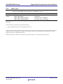
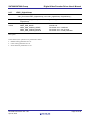
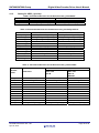
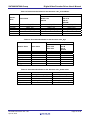
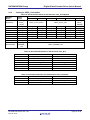
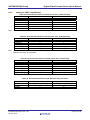
4.1.2
Digital Video Decoder Driver User's Manual
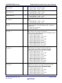
Setting for VDEC_SyncSep
Table 9 Recommended Value for the Structure vdec_NoiseRdLPF
Member Name
Lpfvsync
Lpfhsync
Initial Value
VDEC_LPF_VSYNC_0_54
VDEC_LPF_HSYNC_1_34
Recommended Value
VDEC_LPF_VSYNC_0_54
VDEC_LPF_HSYNC_0_94
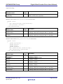
Table 10 Recommended Value for the Structure vdec_AtLvCtrlSyncSlicer
Member Name
Velocityshift_H
Slicermode_H
Slicermode_V
Syncmaxduty_H
Syncminduty_H
Ssclipsel
Csyncslice_H
Syncmaxduty_V
Syncminduty_V
Vsyncdelay
Vsyncslice
Csyncslice_V
Initial Value
Recommended Value
VDEC_VELOCITY_SHIFT_1
VDEC_VELOCITY_SHIFT_4
VDEC_SLICE_MODE_AUTO_50 VDEC_SLICE_MODE_AUTO_50
VDEC_SLICE_MODE_AUTO_50 VDEC_SLICE_MODE_AUTO_50
15u
15u
10u
10u
VDEC_CLIP_LV_1023
VDEC_CLIP_LV_1023
146u
146u
15u
15u
10u
9u
VDEC_OFF
VDEC_OFF
11u
10u
146u
146u
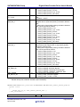
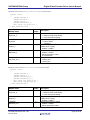
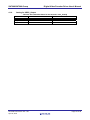
Table 11 Recommended Value for the Structure vdec_HorizontalAfc
Recommended Value
Member
Name
Hafcgain
Hafcfreerun
Hafctyp
Hafcstart
Nox2Hosc
Dox2Hosc
Hafcmax
Hafcend
Hafcmode
Hafcmin
Phdet_Fix
Phdet_Div
Initial Value
6u
VDEC_OFF
692u
0
0
0
742u
8u
2u
642u
0
VDEC_PHDET_DIV_1_32
R01AN0779EJ0100 Rev.1.00
Apr 18, 2013
NTSC-3.58
PAL-M
12u
VDEC_OFF
692u
0
1u
0
792u
8u
2u
592u
0
VDEC_PHDET_DIV_1_32
NTSC-4.43
PAL-4.43
PAL-N
SECAM
12u
VDEC_OFF
704u
0
1u
0
785u
8u
2u
630u
0
VDEC_PHDET_DIV_1_32
Page 46 of 58
SH7268/SH7269 Group
Digital Video Decoder Driver User's Manual
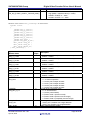
Table 12 Recommended Value for the Structure vdec_VcountDown
Recommended Value
Member
Name
Vcdfreerun
Novcd50
Novcd60
Vcddefault
Vcdwindow
Vcdoffset
Initial Value
NTSC-4.43
PAL-4.43
PAL-N
SECAM
VDEC_OFF
VDEC_OFF
VDEC_OFF
VDEC_ON
VDEC_ON
VDEC_OFF
VDEC_VCNT_FRQ_59_94HZ VDEC_VCNT_FRQ_50HZ
30u
30u
15u
15u
NTSC-3.58
PAL-M
VDEC_OFF
VDEC_ON
VDEC_ON
VDEC_VCNT_FRQ_AUTO
20u
10u
Table 13 Recommended Value for the Structure vdec_Agc
Member Name
Agcmode
Doreduce
Noreduce
Agcresponse
Agclevel
Agcprecis
Pga_gain
Initial Value
VDEC_OFF
0
0
5u
236u
10u
0
Recommended Value
PAL-4.43
PAL-M
NTSC-3.58
PAL-N
NTSC-4.43
SECAM
VDEC_ON
VDEC_ON
0
0
0
0
4u
4u
230u
242u
10u
10u
0
0
Table 14 Recommended Value for the Structure vdec_PeakLimCtrl
Member Name
Peaklevel
Peakattack
Peakrelease
Peakratio
Maxpeaksamples
R01AN0779EJ0100 Rev.1.00
Apr 18, 2013
Initial Value
VDEC_PEAKLV_LIM_OFF
2u
0
VDEC_PEAKRATIO_50
0
Recommended Value
VDEC_PEAKLV_992
2u
3u
VDEC_PEAKRATIO_50
20u
Page 47 of 58
SH7268/SH7269 Group
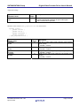
4.1.3
Digital Video Decoder Driver User's Manual
Setting for VDEC_YcSep
Table 15 Recommended Value for the Structure vdec_YcSepCtrl
Recommended Value
Member Name
K15
K13
K11
K16
K14
K12
K22A
K21A
K22B
K21B
K23B
K23A
K24
Hbpf_Narrow
Hvbpf_Narrow
Hbpf1_9Tap_On
Hvbpf1_9Tap_On
Hfil_Tap_Sel
Det2_On
Hsel_Mix_Y
Vsel_Mix_Y
Hvsel_Mix_Y
V_Y_Level
Det2_Mix_C
Det2_Mix_Y
Fil2_Mode_2D
Fil2_Narrow_2D
Initial Value
2u
8u
4u
3u
16u
1u
64u
6u
16u
6u
6u
3u
5u
VDEC_FILSEL_17TAP
VDEC_FILSEL_17TAP
VDEC_BPFSEL_17TAP
VDEC_BPFSEL_17TAP
VDEC_BPFSEL_17TAP
VDEC_ON
VDEC_FILMIX_RATIO_0
VDEC_FILMIX_RATIO_0
VDEC_FILMIX_RATIO_0
3u
VDEC_FILMIX_RATIO_0
VDEC_FILMIX_RATIO_75
VDEC_FILMODE_CASCADE
VDEC_FILSEL_17TAP
R01AN0779EJ0100 Rev.1.00
Apr 18, 2013
NTSC-3.58
NTSC-4.43
2u
8u
4u
3u
16u
8u
32u
6u
8u
6u
6u
3u
5u
PAL-4.43
PAL-M
PAL-N
2u
8u
3u
4u
63u
2u
32u
10u
15u
10u
3u
3u
8u
SECAM
2u
8u
4u
3u
16u
1u
32u
10u
15u
6u
3u
3u
8u
VDEC_FILSEL_BYPASS
VDEC_FILSEL_BYPASS
VDEC_BPFSEL_17TAP
VDEC_BPFSEL_17TAP
VDEC_BPFSEL_17TAP
VDEC_ON
VDEC_FILMIX_RATIO_75
VDEC_FILMIX_RATIO_75
VDEC_FILMIX_RATIO_0
0
VDEC_FILMIX_RATIO_0
VDEC_FILMIX_RATIO_25
VDEC_FILMODE_CASCADE
VDEC_OFF
VDEC_FILMIX_RATIO_0
VDEC_FILMIX_RATIO_0
VDEC_FILMIX_RATIO_0
0
VDEC_FILMIX_RATIO_0
VDEC_FILMIX_RATIO_0
VDEC_FILMODE_BYPASS
VDEC_ON
VDEC_FILMIX_RATIO_75
VDEC_FILMIX_RATIO_75
VDEC_FILMIX_RATIO_0
0
VDEC_FILMIX_RATIO_0
VDEC_FILMIX_RATIO_0
VDEC_FILMODE_CASCADE
VDEC_FILSEL_17TAP
Page 48 of 58
SH7268/SH7269 Group
Digital Video Decoder Driver User's Manual
The recommended values of the chroma filter TAP coefficient parameter for Y/C separation are shown below. The
recommended values for the filter TAP coefficient parameters vary depending on the settings in Fil2_Mode_2D and
Fil2_Narrow_2D. In case of PAL format, the recommended value of Fil2_Mode_2D is
VDEC_FILMODE_BYPASS (see Table 15), so it is unnecessary to set the chroma filter TAP coefficient parameter for
Y/C separation. In case of NTSC format, the recommended values are equal to the initial values.
Table 16 Recommended Value for the Structure vdec_ChrFilTAP
Recommended Value
Initial
PAL-4.43
Member Name
NTSC-3.58
Value
PAL-M
NTSC-4.43
PAL-N
0x0018
0x0018 (24)
0x002C
0x002C (44)
0x0014
0x0014 (20)
0x1034
0x1034 (-52)
Fil2_2D_F[ ]
0x1080
0x1080 (-128)
(WA_F0 ~ WA_F8)
0x1080
0x1080 (-128)
0x100C
0x100C (-12)
0x0084
0x0084 (132)
0x00C8
0x00C8 (200)
0x100C
0x0028
0x003C
0x000C
Fil2_2D_F[ ]
0x1068
(WB_F0 ~ WB_F8)
0x109C
0x1040
0x0078
0x00D0
0x0018
0x0018 (24)
0x002C
0x002C (44)
0x0014
0x0014 (20)
0x1034
0x1034 (-52)
Fil2_2D_F[ ]
0x1080
0x1080 (-128)
(NA_F0 ~ NA_F8)
0x1080
0x1080 (-128)
0x100C
0x100C (-12)
0x0084
0x0084 (132)
0x00C8
0x00C8 (200)
0x1438
0x0AF0
0x1CEC
0x065C
Fil2_2D_F[ ]
0x05A4
(NB_F0 ~ NB_F8)
0x1CEC
0x085C
0x0178
0x1568
Note: Values in the parentheses are presented in decimal form.
R01AN0779EJ0100 Rev.1.00
Apr 18, 2013
SECAM
0x1014 (-20)
0x0018 (24)
0x0040 (64)
0x0028 (40)
0x104C (-76)
0x10A4 (-164)
0x1054 (-84)
0x006C (108)
0x00D8 (216)
0x100C (-12)
0x0028 (40)
0x003C (60)
0x000C (12)
0x1068 (-104)
0x109C (-156)
0x1040 (-64)
0x0078 (120)
0x00D0 (208)
0x13F0 (-1008)
0x07B8 (1976)
0x17E8 (-2024)
0x01BC (444)
0x074C (1868)
0x1B30 (-2864)
0x0548 (1352)
0x0560 (1376)
0x18C0 (-2240)
0x1438 (-1080)
0x0AF0 (2800)
0x1CEC (-3308)
0x065C (1628)
0x05A4 (1444)
0x1CEC (-3308)
0x085C (2140)
0x0178 (376)
0x1568 (-1384)
Page 49 of 58
SH7268/SH7269 Group
Digital Video Decoder Driver User's Manual
Table 17 Recommended Value for the Structure vdec_OverRange
Member Name
Radj_O_Level0
Radj_U_Level0
Radj_O_Level1
Radj_U_Level1
Radj_O_Level2
Radj_U_Level2
Test_Moni
Radj_Mix_K_Fix
Ucmp_Sw
Dcmp_Sw
Hwide_Sw
R01AN0779EJ0100 Rev.1.00
Apr 18, 2013
Initial Value
1023u
0
1023u
0
1023u
0
0
0
VDEC_OFF
VDEC_OFF
VDEC_ON
Recommended Value
992u
64u
960u
48u
928u
32u
0
0
VDEC_ON
VDEC_ON
VDEC_ON
Page 50 of 58
SH7268/SH7269 Group
4.1.4
Digital Video Decoder Driver User's Manual
Setting for VDEC_ChromaDec
Table 18 Recommended Value for the Structure vdec_ColorSysDet
Member
Name
Defaultsys
Nontsc358
Nontsc443
Nopalm
Nopaln
Nopal443
Nosecam
Lumadelay
Chromalpf
Demodmode
Recommended Value
NTSC-3.58
NTSC-4.43
Initial
Value
VDEC_CSYS_NTSC
VDEC_ON
VDEC_ON
VDEC_ON
VDEC_ON
VDEC_ON
VDEC_ON
0
VDEC_OFF
VDEC_DEMMD_PAL
PAL-4.43
VDEC_CSYS_NTSC
VDEC_ON
VDEC_OFF
VDEC_OFF
VDEC_OFF
VDEC_OFF
VDEC_OFF
VDEC_OFF
VDEC_ON
VDEC_OFF
VDEC_OFF
VDEC_OFF
VDEC_OFF
PAL-M
PAL-N
VDEC_CSYS_PAL
VDEC_OFF
VDEC_OFF
VDEC_OFF
VDEC_OFF
VDEC_ON
VDEC_OFF
VDEC_OFF
VDEC_OFF
VDEC_ON
VDEC_OFF
VDEC_OFF
VDEC_OFF
VDEC_OFF
VDEC_OFF
VDEC_OFF
VDEC_ON
VDEC_OFF
VDEC_OFF
SECAM
VDEC_CSYS_SECAM
VDEC_OFF
VDEC_OFF
VDEC_OFF
VDEC_OFF
VDEC_OFF
VDEC_ON
0
VDEC_OFF
VDEC_DEMMD_PAL
Table 19 Recommended Value for the Structure vdec_Bco
Member Name
Lockrange
Loopgain
Locklimit
Bcofreerun
Bgpcheck
Bgpwidth
Bgpstart
Initial Value
VDEC_BST_LCKRNG_800HZ
1u
2u
VDEC_OFF
0
36u
130u
Recommended Value
VDEC_BST_LCKRNG_800HZ
3u
1u
VDEC_OFF
0
54u
110u
Table 20 Recommended Value for the Structure vdec_ColorKiller
Member Name
Killeroffset
Killermode
Killerlevel
R01AN0779EJ0100 Rev.1.00
Apr 18, 2013
Initial Value
8u
VDEC_OFF
9u
Recommended Value
5u
VDEC_OFF
4u
Page 51 of 58
SH7268/SH7269 Group
Digital Video Decoder Driver User's Manual
Table 21 Recommended Value for the Structure vdec_AccCtrl
Recommended Value
NTSC-3.58
Member Name
Initial Value
PAL-M
NTSC-4.43 PAL-4.43
PAL-N
SECAM
Accmode
0
0
0
Accmaxgain
VDEC_ACC_MAXGAIN_6 VDEC_ACC_MAXGAIN_6 VDEC_ACC_MAXGAIN_6
Acclevel
292u
220u
230u
Chromasubgain
VDEC_CHR_SUBGAIN_1 VDEC_CHR_SUBGAIN_1 VDEC_CHR_SUBGAIN_1
Chromamaingain
256u
210u
210u
Accresponse
1u
1u
1u
Accprecis
20u
8u
8u
R01AN0779EJ0100 Rev.1.00
Apr 18, 2013
Page 52 of 58
SH7268/SH7269 Group
4.1.5
Digital Video Decoder Driver User's Manual
Setting for VDEC_DigitalClamp
Table 22 Recommended Value for the Structure vdec_PdstlCntrClamp
Member Name
Initial Value
Recommended Value
Dcpresponse
5u
0
Dcpstart
16u
16u
Dcpend
16u
16u
Dcpwidth
54u
27u
PedestalClamp
-*
-*
CenterClamp
-*
-*
Note: * For the settings of PedestalClamp and CenterClamp, see Table 23 and Table 24.
Table 23 Recommended Value for the Structure vdec_PedestalClamp
Member Name
Initial Value
Recommended Value
Dcpmode_Y
1u
1u
Dcpcheck
0
0
Dcppos_Y
162u
162u
Blanklevel_Y
0
984u (-40)*
Clp_Hold_On_Y
VDEC_ON
VDEC_OFF
Note: * The recommended value is -40, but it is necessary to be set in 10-bit 2’s complement form.
Therefore it is set to 984 (0x03D8).
Table 24 Recommended Value for the Structure vdec_CenterClamp
Member Name
Dcpmode_C
Dcppos_C
Blanklevel_Cb
Blanklevel_Cr
Clp_Hold_On_Cb
Clp_Hold_On_Cr
Initial Value
0
27u
0
0
VDEC_ON
VDEC_ON
Recommended Value
0
54u
0
0
VDEC_OFF
VDEC_OFF
Table 25 Recommended Value for the Structure vdec_NoiseDet
Member Name
Acfinput
Acflagtime
Acffilter
R01AN0779EJ0100 Rev.1.00
Apr 18, 2013
Initial Value
VDEC_VDSIG_ATCRR_Y
0
0
Recommended Value
VDEC_VDSIG_ATCRR_Y
0
3u
Page 53 of 58
SH7268/SH7269 Group
4.1.6
Digital Video Decoder Driver User's Manual
Setting for VDEC_Output
Table 26 Recommended Value for the Structure vdec_OutAdj
Member Name
Y_Gain2
Cb_Gain2
Cr_Gain2
R01AN0779EJ0100 Rev.1.00
Apr 18, 2013
Initial Value
512u
512u
512u
Recommended Value
816u
663u
663u
Page 54 of 58
SH7268/SH7269 Group
Digital Video Decoder Driver User's Manual
Website and Support
Renesas Electronics Website
http://www.renesas.com/
Inquiries
http://www.renesas.com/inquiry
All trademarks and registered trademarks are the property of their respective owners.
R01AN0779EJ0100 Rev.1.00
Apr 18, 2013
Page 55 of 58
Revision Record
Rev.
1.00
Date
Apr.18.2013
Description
Page
Summary
—
First edition issued
A-1
General Precautions in the Handling of MPU/MCU Products
The following usage notes are applicable to all MPU/MCU products from Renesas. For detailed usage notes on the
products covered by this manual, refer to the relevant sections of the manual. If the descriptions under General
Precautions in the Handling of MPU/MCU Products and in the body of the manual differ from each other, the
description in the body of the manual takes precedence.
1. Handling of Unused Pins
Handle unused pins in accord with the directions given under Handling of Unused Pins in the manual.
⎯ The input pins of CMOS products are generally in the high-impedance state. In operation with an
unused pin in the open-circuit state, extra electromagnetic noise is induced in the vicinity of LSI, an
associated shoot-through current flows internally, and malfunctions occur due to the false
recognition of the pin state as an input signal become possible. Unused pins should be handled as
described under Handling of Unused Pins in the manual.
2. Processing at Power-on
The state of the product is undefined at the moment when power is supplied.
⎯ The states of internal circuits in the LSI are indeterminate and the states of register settings and
pins are undefined at the moment when power is supplied.
In a finished product where the reset signal is applied to the external reset pin, the states of pins
are not guaranteed from the moment when power is supplied until the reset process is completed.
In a similar way, the states of pins in a product that is reset by an on-chip power-on reset function
are not guaranteed from the moment when power is supplied until the power reaches the level at
which resetting has been specified.
3. Prohibition of Access to Reserved Addresses
Access to reserved addresses is prohibited.
⎯ The reserved addresses are provided for the possible future expansion of functions. Do not access
these addresses; the correct operation of LSI is not guaranteed if they are accessed.
4. Clock Signals
After applying a reset, only release the reset line after the operating clock signal has become stable.
When switching the clock signal during program execution, wait until the target clock signal has
stabilized.
⎯ When the clock signal is generated with an external resonator (or from an external oscillator)
during a reset, ensure that the reset line is only released after full stabilization of the clock signal.
Moreover, when switching to a clock signal produced with an external resonator (or by an external
oscillator) while program execution is in progress, wait until the target clock signal is stable.
5. Differences between Products
Before changing from one product to another, i.e. to one with a different type number, confirm that the
change will not lead to problems.
⎯ The characteristics of MPU/MCU in the same group but having different type numbers may differ
because of the differences in internal memory capacity and layout pattern. When changing to
products of different type numbers, implement a system-evaluation test for each of the products.
Notice
1.
Descriptions of circuits, software and other related information in this document are provided only to illustrate the operation of semiconductor products and application examples. You are fully responsible for
the incorporation of these circuits, software, and information in the design of your equipment. Renesas Electronics assumes no responsibility for any losses incurred by you or third parties arising from the
use of these circuits, software, or information.
2.
Renesas Electronics has used reasonable care in preparing the information included in this document, but Renesas Electronics does not warrant that such information is error free. Renesas Electronics
3.
Renesas Electronics does not assume any liability for infringement of patents, copyrights, or other intellectual property rights of third parties by or arising from the use of Renesas Electronics products or
assumes no liability whatsoever for any damages incurred by you resulting from errors in or omissions from the information included herein.
technical information described in this document. No license, express, implied or otherwise, is granted hereby under any patents, copyrights or other intellectual property rights of Renesas Electronics or
others.
4.
You should not alter, modify, copy, or otherwise misappropriate any Renesas Electronics product, whether in whole or in part. Renesas Electronics assumes no responsibility for any losses incurred by you or
5.
Renesas Electronics products are classified according to the following two quality grades: "Standard" and "High Quality". The recommended applications for each Renesas Electronics product depends on
third parties arising from such alteration, modification, copy or otherwise misappropriation of Renesas Electronics product.
the product's quality grade, as indicated below.
"Standard": Computers; office equipment; communications equipment; test and measurement equipment; audio and visual equipment; home electronic appliances; machine tools; personal electronic
equipment; and industrial robots etc.
"High Quality": Transportation equipment (automobiles, trains, ships, etc.); traffic control systems; anti-disaster systems; anti-crime systems; and safety equipment etc.
Renesas Electronics products are neither intended nor authorized for use in products or systems that may pose a direct threat to human life or bodily injury (artificial life support devices or systems, surgical
implantations etc.), or may cause serious property damages (nuclear reactor control systems, military equipment etc.). You must check the quality grade of each Renesas Electronics product before using it
in a particular application. You may not use any Renesas Electronics product for any application for which it is not intended. Renesas Electronics shall not be in any way liable for any damages or losses
incurred by you or third parties arising from the use of any Renesas Electronics product for which the product is not intended by Renesas Electronics.
6.
You should use the Renesas Electronics products described in this document within the range specified by Renesas Electronics, especially with respect to the maximum rating, operating supply voltage
range, movement power voltage range, heat radiation characteristics, installation and other product characteristics. Renesas Electronics shall have no liability for malfunctions or damages arising out of the
use of Renesas Electronics products beyond such specified ranges.
7.
Although Renesas Electronics endeavors to improve the quality and reliability of its products, semiconductor products have specific characteristics such as the occurrence of failure at a certain rate and
malfunctions under certain use conditions. Further, Renesas Electronics products are not subject to radiation resistance design. Please be sure to implement safety measures to guard them against the
possibility of physical injury, and injury or damage caused by fire in the event of the failure of a Renesas Electronics product, such as safety design for hardware and software including but not limited to
redundancy, fire control and malfunction prevention, appropriate treatment for aging degradation or any other appropriate measures. Because the evaluation of microcomputer software alone is very difficult,
please evaluate the safety of the final products or systems manufactured by you.
8.
Please contact a Renesas Electronics sales office for details as to environmental matters such as the environmental compatibility of each Renesas Electronics product. Please use Renesas Electronics
products in compliance with all applicable laws and regulations that regulate the inclusion or use of controlled substances, including without limitation, the EU RoHS Directive. Renesas Electronics assumes
no liability for damages or losses occurring as a result of your noncompliance with applicable laws and regulations.
9.
Renesas Electronics products and technology may not be used for or incorporated into any products or systems whose manufacture, use, or sale is prohibited under any applicable domestic or foreign laws or
regulations. You should not use Renesas Electronics products or technology described in this document for any purpose relating to military applications or use by the military, including but not limited to the
development of weapons of mass destruction. When exporting the Renesas Electronics products or technology described in this document, you should comply with the applicable export control laws and
regulations and follow the procedures required by such laws and regulations.
10. It is the responsibility of the buyer or distributor of Renesas Electronics products, who distributes, disposes of, or otherwise places the product with a third party, to notify such third party in advance of the
contents and conditions set forth in this document, Renesas Electronics assumes no responsibility for any losses incurred by you or third parties as a result of unauthorized use of Renesas Electronics
products.
11. This document may not be reproduced or duplicated in any form, in whole or in part, without prior written consent of Renesas Electronics.
12. Please contact a Renesas Electronics sales office if you have any questions regarding the information contained in this document or Renesas Electronics products, or if you have any other inquiries.
(Note 1)
"Renesas Electronics" as used in this document means Renesas Electronics Corporation and also includes its majority-owned subsidiaries.
(Note 2)
"Renesas Electronics product(s)" means any product developed or manufactured by or for Renesas Electronics.
SALES OFFICES
http://www.renesas.com
Refer to "http://www.renesas.com/" for the latest and detailed information.
Renesas Electronics America Inc.
2880 Scott Boulevard Santa Clara, CA 95050-2554, U.S.A.
Tel: +1-408-588-6000, Fax: +1-408-588-6130
Renesas Electronics Canada Limited
1101 Nicholson Road, Newmarket, Ontario L3Y 9C3, Canada
Tel: +1-905-898-5441, Fax: +1-905-898-3220
Renesas Electronics Europe Limited
Dukes Meadow, Millboard Road, Bourne End, Buckinghamshire, SL8 5FH, U.K
Tel: +44-1628-651-700, Fax: +44-1628-651-804
Renesas Electronics Europe GmbH
Arcadiastrasse 10, 40472 Düsseldorf, Germany
Tel: +49-211-65030, Fax: +49-211-6503-1327
Renesas Electronics (China) Co., Ltd.
7th Floor, Quantum Plaza, No.27 ZhiChunLu Haidian District, Beijing 100083, P.R.China
Tel: +86-10-8235-1155, Fax: +86-10-8235-7679
Renesas Electronics (Shanghai) Co., Ltd.
Unit 204, 205, AZIA Center, No.1233 Lujiazui Ring Rd., Pudong District, Shanghai 200120, China
Tel: +86-21-5877-1818, Fax: +86-21-6887-7858 / -7898
Renesas Electronics Hong Kong Limited
Unit 1601-1613, 16/F., Tower 2, Grand Century Place, 193 Prince Edward Road West, Mongkok, Kowloon, Hong Kong
Tel: +852-2886-9318, Fax: +852 2886-9022/9044
Renesas Electronics Taiwan Co., Ltd.
13F, No. 363, Fu Shing North Road, Taipei, Taiwan
Tel: +886-2-8175-9600, Fax: +886 2-8175-9670
Renesas Electronics Singapore Pte. Ltd.
80 Bendemeer Road, Unit #06-02 Hyflux Innovation Centre Singapore 339949
Tel: +65-6213-0200, Fax: +65-6213-0300
Renesas Electronics Malaysia Sdn.Bhd.
Unit 906, Block B, Menara Amcorp, Amcorp Trade Centre, No. 18, Jln Persiaran Barat, 46050 Petaling Jaya, Selangor Darul Ehsan, Malaysia
Tel: +60-3-7955-9390, Fax: +60-3-7955-9510
Renesas Electronics Korea Co., Ltd.
11F., Samik Lavied' or Bldg., 720-2 Yeoksam-Dong, Kangnam-Ku, Seoul 135-080, Korea
Tel: +82-2-558-3737, Fax: +82-2-558-5141
© 2013 Renesas Electronics Corporation. All rights reserved.
Colophon 2.2