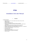
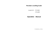
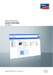
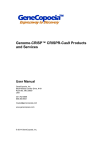
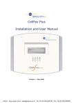
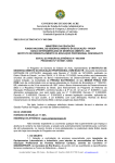
1
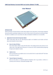
GSM FIXED WIRELESS TERMINAL
WITH
G3
FAX
SUPPORT,
connection and PSTN port
USER MANUAL
Page 1 of 35
GPRS
1 Overview
1.1 Summary
The Fixed Wireless Voice/Data/Fax Access Terminal can
be applied in GSM/GPRS digital mobile communication
networks, serving as Fixed wireless access devices with
functions of phone call, GSM fax sending or receiving, GPRS
connection, caller ID display, power-off bypass and intelligent
routing etc.. No wiring is required. It is featured with easy and
quick installation, plug-and-play within network coverage.
1.2 Product Features
z
z
z
z
z
z
z
z
z
Supporting dual-mode voice access (GSM/PSTN).
GSM Fax function
GSM/GPRS data function
Supporting traditional PBX access
Dynamic echo cancellations to ensure the perfect
voice quality
Power-off bypass functions (when AC power is off, all
calls are switched to PSTN network automatically)
Modem mode (Access the Internet by GPRS
connection via the PC serial port)
Support the phone book stored in the SIM card or in
the terminal
Intelligent routing (Able to set up dialing regulation to
route voice or fax intelligently)
Page 2 of 35
z
z
z
z
z
z
z
Dialing control (Able to set up several special phone
numbers, restricted numbers)
Setup by Keyboard prompt line for convenient
operation.
Incoming call display function
Auto-dialing function
Internal call divert function
Real time displaying of wireless network signal power
Software upgrade
1.3 Technical Specification
Frequency Bands
z GSM 900/1800 MHz
Transmission Power
z EGSM 900 Class4 (2W Peak)
z GSM 1800 Class1 (1W Peak)
Frequency Range
z EGSM 900
890~915 MHz
935~960 MHz
z GSM 1800 1710~1785 MHz
1805~1880 MHz
Power Consumption
z Average power consumption < 5W
Working Environment
z Ambient temperature:0℃~45℃
z Humidity:5%~95%
Power Supply
z DC12V,800mA
Phone port
z Impedance:600ohm(default)
z Open circuit voltage (OCV):63V(on-hook)
z Ringing Load : Support integrating 3 phones
(3REN)
z Provide the control signal of polarity reversal
Page 3 of 35
LAN Interface
z RJ-45 port
z 10M/100M auto-negotiating Ethernet port
RS232 Interface
z RJ-45 to COM serial interface
SIM Card:3V SIM card
Dimensions (L x W x H):
z length×Width×Highness:20.5cm×15cm×4cm
z 0.3 kilogram
1.4 Safety
1、 Please do not use this product in areas where equipment
of wireless transmission is restricted (such as hospital,
health care facilities and on board of aircraft).
2、 Please do not use this product in gas stations, bunkers
and places of chemical storage.
3、 Please do not use this product in chemical plants or any
other places with hazard of explosion (such as gas
leakage site).
4、 Please do not use this product on any metal surface that
might weaken power of received signal.
5、 Please avoid using PSTN network during thunderstorm;
otherwise, it might cause remote electric shock.
Page 4 of 35
2 INSTALLATION INSTRUCTION
2.1 Interface Description
Rear Plate
Interface description:
……… Antenna port
12VDC ………Power supply
……… Power switch
LAN
……… Ethernet port(Optional components)
IOIO ………… Interface of serial port console
PHONE ………Phone port, connected to the regular
phone/fax machine
PSTN………… External PSTN line port,connected to the
PSTN line
Caution: Do NOT plug PSTN line into PHONE
socket; otherwise it may cause device damage.
Page 5 of 35
2.2 Indicators
Indicators
There are 8 indicators on front panel of fixed wireless
terminal, functioning as follows:
1.
GSM Signal Status Indicator
“; they are numbered 1,
GSM has three indicators “
2, and 3 from left to right in sequence.
There are 3 status for indicators:
Continuous lit: Indicating the signal power strength
Slow flash: Flash once per second indicating GSM
general errors
Quick flash:Flash 10 times per second indicating GSM
serious errors
GSM general errors(Slow flash defined as “1”, off defined as
“0”)
110: No SIM card
010: Network registration failure
111: In Modem mode
011: PIN required
GSM serious errors(Quick flash defined as “1”, off defined as
“0”)
001: Lock Base Station
010: Lock the service provider
011: PIN code error
100: IMSI error
Page 6 of 35
101: Require PUK
110: GSM/GPRS baud rate error
111: other errors
2. POWER:Power supply indicator
Light:Indicating device power on
Dark:Indicating device power off
3. PHONE:Phone port status indicator
Light:Indicating the status of talking or hanging up
Flash:Indicating an incoming call and phone ringing
Dark:No call or hang up
4. LINK:The Ethernet connection status indicator
Light:Connection via the Ethernet interface
Dark: No connection via the Ethernet interface
5. STATUS:Device startup status indicator
Light:Device is started up successfully
Slow Flash:Device is starting up
Quick Flash:Device startup failure.
Dark:Device not powered on or starting up. Only after
around 15 seconds does the indicator start flashing
slowly.
Page 7 of 35
2.3 LCD Display
1. The LCD shows“CEL1” when user turns on the power;
then the LCD will show 8888… (totally 14 digits). Another 7
seconds later, appears 16 digits of ‘8’. LCD shows ‘CEL1’
upon successful startup. Start up takes about 30 seconds.
2. When user picks up handset and makes a phone call, LCD
back light is ON, screen clearing up, numbers keyed in
shown up in the screen
3. When there is an incoming call, LCD displays incoming
phone number. (Network or SIM card should support
incoming call display function)
4. When there is incoming call or outgoing call, the LCD will
show the Network
which the calls will go through
(
GSM/GPRS
mobile
network
or
PSTN
telecommunication network). The P indicates the PSTN
voice call,G indicates GSM voice call,F indicate GSM
FAX;D indicates GSM/GPRS data call. When user is on the
call conference, the LCD will display the numbers that are
attending the conference one by one.
5. When user hangs up, LCD displays ‘CEL1” and the
backlight is off in 3 seconds.
6. When the call is on hold, the display will show the new
incoming call. When user switches between two calls, the
display will show the phone number that is on talk. The
display will show all attendees’ number one by one when
the party is on the call conference.
Page 8 of 35
2.4 Modem Mode
GSM/GPRS has two working modes:Common Mode and
Modem Mode. These two modes cannot exist simultaneously.
Common Mode : The wireless access terminal can
provide all the functions except the GPRS under the
Common Mode.
Modem Mode:With peripheral equipment, such as PC,
the user can have access to Internet via GPRS connection
in Modem Mode.
Establishing the Modem Mode:
1. When the user sets the unit into auto-switch mode
(referring to the keyboard setup command below), the PC
serial port needs to be connected to the IOIO port in the
wireless access terminal. Open the serial port in PC, and
then the device will be auto-switched to the Modem mode.
2. Under the Modem Mode, the user can control the
GSM/GPRS modem through the serial port directly. And
user can apply the software in PC to realize the GPRS,
GSM circuit data and computer fax.
3. Using the device under the Modem Mode
a) Under the auto-switch mode(Get the terminal ready
for working; Get the terminal connected with the
telephone set; power on the terminal; pick up the
telephone set and input #*83*1#; hang up to set the
unit into the auto-switch mode ), when there is
incoming call on the GSM, the user can configure the
mode as “Switch to modem mode while ringing” (Get
Page 9 of 35
b)
the terminal ready for working; get the terminal
connected with the telephone set; power on the
terminal; pick up the telephone set; input #*102*1#
and hang up) or “ Switch to modem mode after picking
up the phone” (Get the terminal ready for working; get
the terminal connected with the telephone set; power
on the terminal; pick up the telephone set; input
#*102*2# and hang up).
Under the restricted Modem mode (Get the terminal
ready for working; get the terminal connected with the
telephone set; power on the terminal; pick up the
telephone set; input #*83*2# and hang up ), the
device will not be switched to the Common Mode
when there is incoming call. There is no use to set
the priority by this command #*102*n#. The PRI of
keyboard command “#*83*n#” is higher than #*102*n#.
2.5 Hardware Installation Steps
1、 Put one end of the attached telephone line into the
telephone (Or the line port of Fax and Modem); put the
other end into the ‘Phone’ socket on the rear plate.
Caution: Do NOT plug external PSTN line into PHONE
socket; otherwise it may damage the device.
2、 Connect the external PSTN line to the socket marked
as ‘PSTN” on the rear plate.
Page 10 of 35
3、 Connect and screw up firmly the companied antenna.
Antenna connector is marked as “ ” .
4、 Make sure power switch on the rear plate is in OFF
position. Afterwards, plug one end of companied power
adapter into AC220V power socket, and plug the other
end into “12VDC ”power interface on the rear plate.
5、 Switch on power. The device enters startup status.
When STATUS indicator is on continuously, device
startup is successful and it is ready for use.
6、 Connect the device to the Ethernet and input the IP
address in the URL of the Internet Explore, and then the
user can use the SMS function of this device.(Refer to
the “4.5 Web SMS Function”)
Caution: In order to avoid radio interference on
voice communication, make sure antenna and
telephone line are not twisted. Make sure telephone set
is not placed too close to the antenna; a distance of
over 1 meter is recommended.
Page 11 of 35
3 APPLICATIONS
3.1 Application Model 1
In this application, the unit is connected with regular
telephone, FAX, Modem via phone socket, connected with
external PSTN line via PSTN socket, connected with Ethernet
via Ethernet port. . In normal situation, user can make calls and
or receive calls via GSM network. When there is power failure,
the device will be switched to PSTN network automatically
3.2 Application Model 2:
There are two plans for this model of application.
Plan A:The unit is connected with PBX via PHONE
port. External PSTN line is plugged into the PSTN port on
the unit. Under normal situation, the PBX extension users
can make calls and or receive calls via GSM network.
When there is power failure, the unit will be switched to
PSTN automatically.
Plan B: PBX ( Private Branch (telephone) exchange )
extension access mode. This mode differs from the classic
PBX trunk access. The unit is connected with any PBX
extension. This mode will make the PBX access more flexible
and convenient. If the user wishes to extend the fully loaded PBX
trunk lines or manage the fixed trunk line and wireless trunk line
separately, this mode is a better choice.
Page 12 of 35
The device’s external line socket is connected with PBX
internal interface (EXT ports) or any extension. The PBX
extensions first call the extension number of the terminal and
then make calls by the terminal using GSM network.
Operation Instruction
4.1 Telephone Function
4.1.1 Making a phone call
1) Off-hook:Pick up the handset; you will hear a dialing
tone.
2) Dial:Dial the phone number, the system will send out
your dialed number automatically.
3) Conversation:When recipient picks up handset at the
other end, voice communication is established.
4) Clear:Clear after hanging up.
4.1.2 Receiving a phone call
When phone bell is ringing, PHONE indicator is blinking;
the user picks up handset to start phone talking.
Page 13 of 35
4.2 Fax function
4.2.1 Sending a fax
User can send faxes by fax machine connected with the
terminal via phone port.
4.2.2 Receiving a fax
User can receive faxes by fax machine connected with the
terminal via phone port.
Note: The terminal does NOT support automatic
switching between GSM voice/Fax. This function needs
GSM/GPRS network support of TS61 (allowing users to
use voice and fax functions in one call). As a result,
when sending a fax, please press START key
immediately after you complete dialing numbers; When
receiving faxes, please set fax machine to AUTO mode.
4.3 Data Function
Users can transmit data through the modem connected
with the terminal via the phone port; methods to use this
modem are exactly the same as the wire-line modem.
Page 14 of 35
4.4 Call Waiting and Three Party Conference
Function
This device supports GSM Call Waiting and three-party
conference function. (Note: Relevant services should be
activated on SIM card).
In the process of conversation, if there’s an incoming call
from the third party, the call receiver will hear the prompt tone in
the terminal and its LCD will show the new incoming call
number.
z
If the receiver wants to ignore this incoming call, just take
no operation.
z
If the receiver wants to reject this incoming call, press R
button and then 0.
z
If the receiver wants to end the current conversation and
starts the new conversation, press R button and then
press 1. Or hang up the phone to end current
conversation and pick up the phone (the phone will be
ringing after hang-up) for new incoming call.
z
If the receiver wants to hold the current conversation and
accept the new call, press R button and then press 2.
The receiver can also switch between the two phone
calls by pressing 2. The LCD will show the number of
current phone conversation.
z
In the process of conference, the user can press the
button R and # to hold the current call, then he can dial a
new number after hearing the dial tone.
z
When the receiver makes a new call and the talk is
Page 15 of 35
established, the former conversation will still be on hold.
If the receiver wants to hold the three-party conference,
press button R and then 3 to add the current
conversation into the conference. This realizes the
z
z
z
3-party conference. The LCD will show in scroll the
participators’ number.
Hang up the telephone set connected with the terminal to
end the conference.
Press the button R and then 1X to end the conversation
with one party.(x means the sequence number of the call
displayed on the LCD)
If the receiver wants to have a private conversation
with one party, press button R and then 2x (x means
the sequence number of the call displayed on the LCD )
Caution: Pressing the hook has the same effect in
case some telephones do not have button R.
4.5 Web SMS Function
To use web SMS function, the user needs to connect the
PC with the terminal via the LAN port (Ethenet port). The user
can send and receive short messages through the WEB page
after connection.
The default IP address of the Wireless Voice/Data/Fax
Access Terminal is 192.168.10.1. The user can configure the IP
address by the CLI and can resume the IP address to default
configuration by the keyboard command. (Refer to the
Page 16 of 35
following“4.7 Keyboard Configuration Command”to learn the
detailed keyboard commands)
The process of using Web SMS function as follows:
1.Open the Internet Explorer on the PC and input the address
http://192.168.10.1(The default IP address of the device). Input
the user name and password.(The default values are both
admin)
2.Enter the transmission interface of Web SMS,under this
interface, the user can send and receive the short
messages on the prompt menu.
Page 17 of 35
4.6 Call Diversion Function
Call diversion means that the system diverts the calls of
PSTN and GSM.
There are two modes of the call diversions:
A. Diverting from PSTN to GSM ( Set by keyboard
command):
i. Call forwarding when No Reply. When there is an
incoming PSTN call,the phone begins to ring. Ring
numbers can be set by telephone set keyboard
command. If there is no answer, the terminal will call the
appointed number via GSM (The appointed number
was set by telephone keyboard commands) and link the
PSTN voice channel with GSM voice channel. When
the GSM call is put through, the caller (on the PSTN line)
and the receiver (on the GSM line) can talk with each
other. Actually it is GSM to GSM call.
Page 18 of 35
ii. Call forwarding with no condition. Call the pre-set
number through GSM when there is an incoming PSTN
call.
B. Call diversion from GSM to PSTN ( Set by keyboard
commands)
,support only one diversion mode:
i. Diversion without condition. When there is an incoming
GSM call , the device will call the pre-set number
through the PSTN line. ( The number was set by
keyboard commands.)
Remark:Refer to the correlative commands of the call
diversion in “ 4.7 Keyboard Configuration
Command”.
Caution:
1. The call diversion function can reduce the phone bill
cost when the user is out of the relevant location.
2. After activating the call diversion, the terminal cannot
receive any calls via phone port. When there is no
response in the terminal after you pick up the
telephone handset and there is no dialing tone in the
handset, it indicates that the system is in the condition
of call diversion. The user should cancel call diversion
when the user does not need this function to ensure
the common use of the terminal.
Page 19 of 35
4.7 Keyboard Configuration Command
User may set command by using keyboard of telephone
set connected to the phone socket. The following commands
are effective for the wireless access terminal.
4.7.1 System Configuration
1. Set working mode
Command:#*1*working mode#
Description:Set the working mode of terminal,Working
mode = 0 is 30 mode;1is 31 mode;2 is 32a mode;3
is 32b mode
2. Current work mode display
Command:#*11#
Description:Display the device’s current working mode.
3. Set system date
Command:#*20*y*m*d#
Description:Set the system date, y means(00~99);
m means month(0~12);d means day(0~31)
4. Set system time
Command:#*21*h*m*s#
Description : Set the system time of the device, h
means hour(0~24);m means minute(0~59);s
means second(0~59).
5. Set auto-dialing delay
Command:#*3*seconds#
Page 20 of 35
Description : Set up dialing overtime and auto
sending-out time upon complete entry of numbers,
default setting: 3 seconds.
<seconds>
Set point range 1-20 s
6. Set external line flash key delay
Command:#*4* delay #
Description:Set external line flash key delay, default,
700ms delay
<delay>
0~2000 ms
7. External line flash key delay Display
Command:#*41#
Description:Display external line flash key delay
8. GSM/GPRS signal quality display
Command:#*50#
Description:Display GSM/GPRS signal quality
9. GSM IMEI Display
Command:#*51#
Description:Display GSM IMEI
10. SIM IMSI Display
Command:#*52#
Description:Display SIM card IMSI
11.Set GSM output voice volume
Command:#*53*volume#
Description:Set GSM output voice volume,volume
Page 21 of 35
(0~4).
12.Set SMS center number
Command:#*58*n*number#
Description:Set SMS center number (When n=0, do
not add prefix before the number. When n=1, add the
prefix “+” before the number)
13. SMS center number Display
Command:#*59 # SMS center number
Description:Display SMS center number
14.Software version display
Command:#*60#
Description:Display software version
15. GSM version display
Command:#*61#
Description:Display GSM version
16.The parameter of echo cancellation display
Command:#*62#
Description:Display parameter of echo cancellation
17.Set echo cancellation switch
Command:#*63*n#
Description:Set echo cancellation switch ,When n is 0
means echo cancellation off,1 is on.
18.Set the emergency call number
Page 22 of 35
Command:#*65*emergentNumber#
Description : Set the emergency call number ,
emergentNumber is the emergency call number.
19.Set the emergency dialing time
Command:#*66*seconds#
Description : Set the time from picking up to
auto-sending of the emergency number by the device.
Seconds(0~10)is the time that defined by user. It
indicates that the user do not dial the number after
picking up, the device will dial the emergency number
after Seconds automatically. If Second is 0, that
indicate the emergency dialing function has been off.
20.Set FAX and Voice Ring both
Command:#*68*n#
Description:Set FAX and Voice Ring both,when n is 0
means off, and 1 means on. This function will not be
effective on the hardware board version 2.0.
21.Set PSTN line type
Command:#*8* type #
Description:Set PSTN line type,default is long
type
0,long
1, short
2, pbx600
3, pbx900
22.MODEM Test function
Command:#*9#
Page 23 of 35
Description:Test MODEM function
23.Force switch to Modem mode
Command:#*100#
Description:Switch the serial port to Modem mode.
24.Resume the IP address on the Ethernet port to
192.168.10.1
Command:#*101#
Description:Resume the IP address on the Ethernet
port to 192.168.10.1.
25.Set GSM MODEM PRI
Command:#*102*n#
Description:Set GSM MODEM PRI (0=do not switch,
means modem PRI is high ; 1=switch, means that
common mode PRI is high, 2=switch after response).
26.Minute Prompt
Command:#*110*n#
Description:n=1,the device will send a prompt tone per
one minute during user’s conversation.
n=0,this function is off.
4.7.2 set the call diversion of interface
i.
Set the diversion from FXO to GSM
Command:#*70*n#
Description:Set the diversion switch from FXO to
GSM(n=0:Off;n=1: On).
Page 24 of 35
ii.
Set the diversion number from FXO to GSM
Command :#*71*number#
Description:Set the diversion number from FXO to
GSM. It is the number dialed from GSM port.
iii.
Set the appointed incoming call number by FXO
Command:#*72*number#
Description:Set the appointed incoming call number
by FXO. When the incoming call number is the
appointed number on FXO port the device will regard
this incoming call as special.
iv.
Clear the incoming call number appointed by FXO
Command:#*73#
Description: Clear the appointed incoming call
v.
Set no answer delay for FXO
Command:#*74*time#
Description:Set no answer delay time for FXO
vi.
Set the FXO call diversion type
Command:#*75*n#
Description:Set the FXO call diversion type (0=divert
always;1=divert when no answer)
vii.
Set the call divert from GSM to FXO
Command:#*76*n#
Description:Set the call divert from GSM to FXO(0=
no dialing from FXO ;1= dialing from FXO)
Page 25 of 35
viii.
Set the call divert number from GSM to FXO
Command:#*77*number#
Description: Set the call diversion number from GSM
to FXO. When the function of call diversion from GSM
to FXO is on, GSM dials this number from FXO port.
ix.
Force the call in as the FAX switch
Command:#*78*n#
Description:When n=0 ,the incoming call will be
regarded as common call by the device,
When n=1 ,the incoming call will be regarded as
FAX by the device,
4.7.3 Detecting the caller ID format:
1. Detect the current caller ID format
Command:#*99#
Description: Detect the current caller ID format. After
completing this command, the user should hang up the
phone immediately. If the current caller ID format is
complied with local standard, the user’s CLI display will
show “0123456789”. If the device can not display this
character string, the user will need to change the
current standard of caller ID by command “#*81*n#”.
2. Set the device to support the three different standards
of caller ID:
Command:#*81*n#
Description: Set the device to support the three
different standards of caller ID identification.
(0=Off;1= ETSI DTMF;2= ETSI V.23;3= Bellcore)
Page 26 of 35
(Default value is 3)
3. Set keyboard command for transmitting caller ID during
calling
Command:#*82*n#
Description: You can decide by yourself to transmit
your numbers when you are making phone calls by this
command. (0=Not transmitting your numbers when
making a phone call;1= Transmitting your numbers
when making a phone call).
4.7.4 Set series port switch
1. Set series port switch
Command:#*83*n#
Description: Set series port switch (0=Off;1=CLI;
2=MODEM).
4.7.5 Set overtime of Button R
1. Set overtime of Button R
Command:#*85*n#
Description: Set overtime of Button R
4.7.6 Set SIM Card
1. Input PIN code
Command:#*86*n#
Description: Input PIN code,n is the PIN code to be
input by the user.
2. Modify PIN code
Command:#*88*oldpin*new*newV#
Page 27 of 35
Description: Modify PIN code. The “Oldpin” is old PIN code,the
“New” is new PIN code,the “NewV” is confirm new PIN code.
3. Input PUK code
Command:#*89*PUK*PIN#
Description: Input PUK code,PUK is input by user,PIN
is new PIN code input by user
4. Set PIN code function
Command:#*90*n*pin#
Description: Set PIN code function (n=0 PIN function
disabled;n=1 PIN function enabled)
5. Query PIN function status
Command:#*91#
Description: Query whether PIN function status on or
off
4.7.7 Phone book Function
1. Store the number into the SIM card
Command:#*120*pos*n#
Description: Store the number “N” into the position
“Pos” in the phonebook in the SIM card
2. Delete the number stored in the SIM card
Command:#*121*pos#
Description: Delete the number on the position “Pos” in
the phonebook in the SIM card
3. Query the number stored in the SIM card
Page 28 of 35
Command:#*122*pos#
Description: Query the number on the position “Pos” in
the phonebook of SIM card
4. Dial the number stored in the SIM card
Command:Pos#
Description: Dial the number on the position “Pos” in
the phonebook in the SIM card
5. Store the number into the device
Command:#*125*pos*n#
Description: Store the number on the position “Pos” in
the phonebook
6. Delete the number stored in the device
Command:#*126*pos#
Description: Delete the number stored on the position
“Pos” in the phonebook
7. Query the number stored in the device
Command:#*127*pos#
Description: Query the number on the position “Pos” in
the phonebook
8. Dial the number stored in the device
Command:pos*
Description: Dial the number on the position “Pos” in
the phonebook
4.7.8 Call charging function
Page 29 of 35
1.
Call charging function
Command:#*95*n#
Description: Call charging function switch on or off
(0=Off;1=on)
2.
Set charging mode
Command:#*96*n#
Description: Set charging mode (0=FEE_APR_S ;
1=FEE_APR_D;2= FEE_APR_NO
3.
Set the frequency of detecting polarity reversal signal
on the FXO port per second
Command:#*98*n#
Description: Set the frequency of detecting polarity
reversal signal on the FXO port per second(n=2~10)
4.7.9 GSM network configuration
Command
code
*
**
*#
#
##
Page 30 of 35
Function
Activate
Register and activate
Status check
Disable
Un-registered and disabled
Abbreviation
DN
Meanings
Dialing number(number)
Voice(wave)
FAX
SMS(short message service)
SMS+FAX
Data circuit asynchrony
Data circuit synchron
Dedicated PAD access
Dedicated Packet access
Data circuit asynchron+PAD
Data circuit synchron+Packet
Data circuit asynchrony
+Synchron+Packet+PDA
All Services
Time in seconds
BS
T
1.
GSM divert always
Command:(*|#|*#|**|##) 21*DN*BS#
Description:GSM diversion always
2.
GSM diverting on busy
Command:(*|#|*#|**|##) 67*DN*BS#
Description:GSM diverting on busy
3.
GSM diverting No Reply
Command:(*|#|*#|**|##) 61*DN*BS#
Description:GSM divert when no one reply
4.
GSM diverting No Signal
Page 31 of 35
Value
String of
digits 0~9
11
13
16
12
25
24
27
26
21
22
20
--
Command:(*|#|*#|**|##) 62*DN*BS#
Description:GSM divert if there is no signal in service
area
5.
GSM diverting all calls
Command:(*|#|*#|**|##) 002*DN*BS#
Description:GSM diverting all calls
6.
GSM diverting All Conditions
Command:(*|#|*#|**|##) 004*DN*BS#
Description:GSM diverting call under all conditions
7.
GSM outgoing call limited
Command:(*|#|*#) 33*PW*BS#
Description:GSM outgoing calls are limited
8.
GSM international call restricted
Command:(*|#|*#) 331*PW*BS#
Description:GSM restricts the outgoing international
call
9.
GSM international call restriction except in the
homeland
Command:(*|#|*#) 332*PW*BS#
Description : GSM restricts all the international call
except in the homeland
10. GSM all incoming call restriction
Command:(*|#|*#) 35*PW*BS#
Description:GSM restricts all the incoming call
Page 32 of 35
11. GSM all incoming call restriction roaming
Command:(*|#|*#) 351*PW*BS#
Description : GSM restricts all incoming call during
roaming
12. GSM enables/disables call waiting
Command:(*, #, *#43#)
Description:GSM enables/disables call waiting function
Page 33 of 35
5 Frequently Asked Questions
Q: How long do I wait till I am able to make a phone call or
fax?
A: It takes 30 seconds for start-up. System goes into normal
operation after LCD and indicators showing “CEL1”.
Q: What will happen if I make a wrong connection to phone
socket and External line socket?
A: No mistake is allowed for connections of phone socket (for
the connection of telephone set or fax machine) and External
line socket (TRUNK, for PSTN line). Wrong connection may
cause system failure and even burns down hardware chips
seriously.
Q: Why does the device always send the FAX as a voice
outgoing call?
A: Some outdated FAX machine cannot send the identification
tone, the user must add the “*01*” before the number to prompt
the system that this call is a FAX call (Such as *01*Number).
Q: Why does the device always make the voice outgoing call
when user makes the data call?
A: Some outdated Modem cannot send the CNG identification
tone, so the user should add the “*02*” before the number to
prompt the system that this call is Data call (Such as
*020*Number).
Q: Is it possible to transmit fax via GSM by any SIM card?
Page 34 of 35
A: Before using GSM fax function, the user makes sure that:
(a) For sending faxes, ensure SIM card data transmission
service is available (GSM network support is required)
(b) For receiving faxes, ensure SIM card fax receiving
service is available. (GSM network support is required;
usually this function needs dual number with one SIM
card – one voice number and one fax number. For fax
receiving, only fax number is used. Voice number is not
used for fax receiving.)
Q: What type of fax machine do I need to use?
A: Any G3 standard fax machine with AUTO mode available is OK.
Q: When I use GSM fax, is it possible to fax like desktop fax
machine, i.e. make a phone call before sending faxes?
A: Not possible. This terminal does not support GSM voice/ fax
switching function. This function requires GSM/GPRS network
supporting TS61 (allowing user to make phone call while faxing). So,
when sending faxes, please press down Start key immediately after
completing your number; when receiving faxes, please set fax
machine to Auto mode.
Page 35 of 35