1
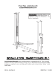
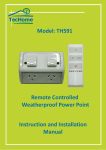
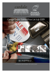
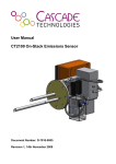
Instructions for fitting your
Cardale Autoglide operator
IMPORTANT SAFETY INSTRUCTIONS
FOR INSTALLATION
WARNING – INCORRECT INSTALLATION CAN
LEAD TO SEVERE INJURY FOLLOW ALL
INSTALLATION INSTRUCTIONS
Before installing the operator check that the door is in
good mechanical condition, and correctly balanced, and
that it opens and closes properly.
Do not use the force adjustments to compensate for
a binding or sticking garage door. Excessive force will
interfere with the proper operation of the Safety Reverse
System or damage the garage door.
Do not wear rings, watches or loose clothing while
installing or servicing a garage door operator.
To avoid serious personal injury from entanglement,
remove any ropes connected to the garage door before
installing the door operator.
Install the remote mounted bell push button within
sight of the door but away from any moving parts and
at a height of at least 1.5 metres.
Permanently fix the label warning of entrapment in a
prominent place or near the remote bell push button.
The safety reverse system test is very important.
The garage door must reverse when obstructed on
closing. Failure to properly adjust the operator may
result in serious personal injury from a closing garage
door. Repeat the test once a month and make any
needed adjustments (see Section 7 in manual –
Safety sensitivity check.)
SAFETY NOTE: If there is a chance that children
may play in the entry of the garage then ensure
the child lock is ENABLED so that the door CANNOT
be operated from the
button (see Section 6c).
Installation and wiring must be in compliance with your local building
and electrical codes. Connect the power cord only to properly earthed mains.
Use a ring main 13 amp 3 pin socket installed by a qualified electrician.
The plug should be fitted with a 5 amp fuse.
THIS APPLIANCE MUST BE EARTHED.
NOTE: For optimum electrical safety this operator should be
connected to a circuit protected by an R.C.D. (max. 30mA trip rating)
If the garage has no service entrance door then an exterior release kit
MUST be fitted. This accessory allows manual operation of the garage
door from outside in case of power failure. (See back page)
Disconnect electric power to the garage door operator before making
repairs or removing covers.
Use the manual release lever to disengage the motor drive ONLY when
the drive is switched OFF and, if possible, when the door is fully closed.
Examine the installation, in particular the cables, spring and
mountings, for signs of wear, damage or imbalance. Do not use if repair
or adjustment is needed since a fault in the installation or an incorrectly
balanced door may cause injury.
IMPORTANT SAFETY NOTE
Only operate the door when the door is in full view, free of obstacles
with no persons (particularly children) near the door. Nobody should
be allowed to enter or leave the garage whilst the door is in motion.
1 Pre-installation checks
A
Fit only to Cardale CD 45 and CD PRO garage doors, conversion kits
are required for fitting to other trackless gear systems. (See back page)
B
Do not fit Autoglide to any door larger than 8' 0" wide × 7' 0" high
(2438 × 2134mm).
C
The timber “goalpost‘’ frame must be a minimum of 70mm wide at
the right-hand side of the door looking from the inside of the garage and
the frame must be in good condition and securely fixed.
D
Ensure the door is correctly tensioned and properly lubricated.
The operator will not function properly if the door is poorly installed in
any way. Also check that lifting cables and gear are in good condition.
E
Prior to installing your Autoglide unit ensure all tools, etc are
available inside the garage.
2
F
Ensure that there is a suitably positioned 240v 13A socket outlet
available inside the garage, this must be earthed.
Cut out for
limit switch
Open limit
switch
Drive track
containing
Dymetrol
drive tape
Latch lever
Triangular
gusset and
cable adjuster
Latch release
cable
Spindle
Drive carriage
Manual release
lever
Close limit
switch
Tilt pin
Tilt bracket
Drive motor
and cover
•
View of Autoglide track unit from inside the garage (door bracing may vary)
3
2 Parts check list
Please check box contents and collect necessary tools
ITEM NO.
PART CHECK
QUANTITY
1
Operator/track unit
1
2
Power lead
1
3
Handset
1
4
Assorted screws/fixing
5
Tilt bracket
1
6
Cable clamp moulding
1
7
Gusset plate
1
8
Spacer
1
9
Special spindle
1
10
Push button control and fixings
1
11
Lamp output connector
1
12
Frame door fixing pack.
1
13
Lamp holder (where supplied)
14
Latch release cable outer
1
15
Fittings/instructions pack for CD PRO
1
1 Bag
6
7
11
8
2
9
1
4
3
5
10
Contents of item 4 (bag)
QTY
ITEM
DESCRIPTION
3
Track fixing screw No 8 × 1” S/tap C’/sunk
2
Chassis fixing screw No. 10 × 2” S/tap Pan HD
2
Cable tie
2
Gusset plate fixing No. 10 × 1/2 ” S/tap Pan HD
2
Yellow wall plug for push button and No. 4 × 1”
S/tap C’/sunk screws
1
Cable clamp for latch cable
1
Split pin to retain door tension
1
Tilt bracket top fixing screw No. 10 × 3/4" ”
S/tap Pan HD
1
Tilt bracket bottom fixing screw No. 8 × 3/4”
S/tap C’/sunk
2
Cable clamp fixing No. 6 × 1/2” S/tap Pan HD
1
Star lock washer for spindle
1
Cable fixture plus nut and washers
Tools required
1
2
3
4
5
Power drill
Masonry bits
Steel drill bit 3.5 diameter
Pliers
Plain screwdriver
6
7
8
9
10
Pozidrive screwdriver
22mm A/F spanner
Hacksaw
Small electrical screwdriver
Tape measure
NOTE: Where the garage door is the only means of access it is
recommended that the optional Exterior Release kit is fitted.
5
IMPORTANT NOTE: If you are fitting to a door supplied
with CD PRO gear use instructions supplied in item 15.
3 Fitting the track assembly
WARNING: The spring is under extreme tension – follow instructions
carefully to avoid personal injury. If in any doubt at all consult a
qualified installer (see Yellow Pages for details).
NOTE: If door is not yet fitted, fit door to opening only after completing stages
1 and 2 (refer to door fitting instructions). Do NOT fit latches at this stage.
1
Cut out a 30mm × 100mm rectangle in top
of right-hand side seal of door (looking
from inside garage) as shown in Figure 1.
NOTE: Later doors already have this cut out.
30 mm
2
Replace existing spindle on right-hand side
of door (looking from inside garage) with
special spindle supplied in accessory pack
100 mm
as follows:–
a. Open door fully and remove screws from
centre of right-hand runner (Figure 2).
Cut out
Side seal
•
Figure 1
b. Close door fully, ensuring latch is
engaged. Grip right-hand (black) cone
pulley with spanner and by turning upwards
align holes in anchor bush and spring shaft.
Insert retaining pin supplied fully into hole
(Figure 3) – and remove spanner.
c. Remove right-hand side runner and
security block by removing screws at top
and bottom of runner (Figures 4 & 5).
Apply
spanner
here
R/H (black)
cone pulley
Spring
anchor
bush
Retaining pin
Runner
6
•
Figure 2
•
Figure 3
Remove top
fixing screw
•
Figure 4
•
Figure 5
d. Lever off star washer from inboard end of
spindle with screwdriver (Figure 5).
NOTE: On later doors remove circlip.
e. Pull door slightly away from frame and
remove spindle. Unhook from cable.
Cable in
groove
N.B. On some installations difficulty may
be experienced in removing spindle pin
because of restricted side room. In extreme
circumstances door may have to be taken out.
f. Loop cable over new spindle, ensuring
loop is located in groove (Figure 6).
g. Refit spindle through hole in bracket.
h. Push new star washer, correct way round,
onto spindle using pliers (or suitable size
pipe if available) ensuring there is no free
play on spindle (Figure 6).
Fit new
starlock
washer
•
Figure 6
DO NOT REPLACE RUNNER
i.
Remove retaining pin by reversing step b.
IMPORTANT NOTE: On CD PRO doors fitted with “floating” wheel
spindles you MUST fit nylon spacer to LH spindle to eliminate end float
(see instructions in item 15).
7
•
3
If door has not yet been fitted, fit now
(refer to door fitting instructions) but
do not fit latches at this stage. If door is
already fitted, remove all latches now.
ENSURE DOOR IS CORRECTLY TENSIONED
AND LUBRICATED
4
Open door three quarters of full opening height.
5
Take the Autoglide track unit and operate
manual release lever (Figure 7) by pushing
towards drive carriage. This will disengage drive
carriage from Dymetrol tape inside the track.
Slide the carriage to a position approximately
305mm (12") from top of track.
6a If door is fitted to a timber frame.
Figure 7
Offer track up to right-hand side of door
and slide spindle into shaped recess in top
of drive carriage (Figure 8a). Position top of
track 25mm (CD45) or 6mm (CD PRO) from
underside of top lintel (Figure 9). Ensure
spindle fits comfortably in recess with 1.0mm
clearance between end of spindle and carrier
housing (Figure 8b).
Screw track to side jamb using 3 off No. 8 × 1"
countersunk self tapping screws provided
(Figure 11) ensuring track is parallel to side
of door.
1.0 mm
Spindle
Recess
Drive
carriage
8
•
Figure 8a
•
Figure 8b
Secure the motor chassis with the two No.10 × 2"
self tapping screws provided (Figure 11).
N.B. On bottom fixing use 1" black spacer insert
provided, to place between chassis plate and frame.
Ensure spacer is correct way round (see Figure 11).
with the screw passing through the spacer.
OPEN/CLOSE DOOR SEVERAL TIMES TO ENSURE
DOOR OPERATES FREELY.
25mm CD45
6mm CD PRO
25 mm
6b If door is fitted to a Steel frame.
IMPORTANT: Your CD45/CD PRO framed door must
be fitted correctly in accordance with the framed
door fitting instructions for behind the brickwork
installation. Unfortunately Autoglide cannot be
fitted to a CD45/CD PRO framed door fitted between
the brickwork (Figure 10).
i Close door fully and prop securely in position.
Remove ONE wall fixing bracket from right-hand
frame side channel. Replace removed bracket
with special cut down bracket supplied (parts list
item 12).
ii
Repeat for other right-hand wall fixing bracket.
•
•
Figure 9
Figure 10
iii Offer track to right-hand side of door and slide
spindle into shaped recess in top of drive carriage.
Align holes in track with pre-pierced holes in
frame channel.
iv Slide one * 3/16" washer between channel and
track and align with centre fixing hole. Fix track
to channel using one No. 8 × 1" self tapping screw
provided.
v
Repeat for other two holes in track.
No.8×1”
countersunk
screws
* 3/16"
vi Secure the motor chassis by sliding one
washer under each fixing hole and using the
two No 10 × 2" self tapping screws supplied.
(Figure 11).
N.B. On bottom fixing use 1" black spacer insert
provided, to place between chassis plate and
frame. Ensure spacer is the correct way round (see
Figure 11) with the screw passing through spacer.
OPEN/CLOSE DOOR SEVERAL TIMES TO
ENSURE DOOR OPERATES FREELY.
Spacer
*NOTE: 3/16" WASHERS NOT REQUIRED ON CD PRO
STEEL FRAMES
•
Figure 11
No.10×2”
panhead
screws
9
4 Fitting the latches
CAM PIN
AT TOP
OF SLOT
Drive
carriage
Fully
down
NOTE: LATCH RELEASE CABLE
To avoid kinking the latch release during
packaging/transit, the outer sheath of the cable
is now supplied as a separate item in the kit box
(item 14).
Prior to fitting the latch release cable (Section 4
in the fitting instructions) you simply need to
slide the outer sheath over the cable that is
already attached to the Autoglide unit then
proceed as per the fitting instructions.
1 Ensure manual lever is still disengaged and
fully close door. Ensure drive carriage is pushed
as far down as it will go i.e. with cam pin at top
of slot. (Figure 12).
Plastic
roller
•
Figure 12
2
Fit tilt bracket to door (Figure 13) 19mm
(3/4") above plastic roller on tilt pin with
drive carriage still fully down.
NOTE: Use the No 8 × 3/4" countersunk
screw in bottom hole and the
No. 10 × 3/4" pan head in the top hole
(Figure 13) use 3.5mm diameter drill.
To top
hatch
Cam
pin
Tilt bracket
Drive
carriage
Fully
down
Latch lever
19 mm
To side
latch
Tilt pin
Plastic
roller
10
Countersunk screw
•
Figure 13
•
Figure 14
Nominal 6mm
Engagement
Fix here
Latch pin
Latch plate
Hole level
with lower hook
•
3
Fix here
Figure 15
Fit eurolock handle as per door fitting
instructions and turn fully anti-clockwise
(when viewed from outside). Place lock
cam onto lock spindle with the tang
Stiffener configuration may var y
•
Figure 16
pointing downwards, fit latch lever over
lock cam in orientation shown (Figure 14)
and secure using self tapping screw and washer.
4
Attach top and left-hand side latches as per door fitting instructions and
attach cables to hooks on latch lever in configuration shown (Figure 14).
Latch cable lengths must be adjusted to give approximately 6mm
engagement of latch pins (Figure 15).
5
Attach triangular gusset plate to stiffener situated
to the right of the latch lever (Figure 16). The
gusset must be located with the lower 8mm
diameter hole level with the lowest hook on the
latch lever (Figure 16). Fix gusset to stiffener using
2 off No. 10 × 1/2" self tapping screws provided.
(Drill holes 3.5mm diameter).
6
Attach cable adjuster through lower 8mm hole in
corner gusset ensuring threaded end of adjuster
is pointing towards latch lever and is screwed
completely into adjuster block (Figure 17).
NOTE: Highest hole on corner gusset should be
kept available for exterior release system. The
exterior release system is available from
Cardale as an accessory.
•
Figure 17
11
7
Route latch release cable through cable
adjuster and fix to door as shown (Figure 18)
using cable ties supplied. Aim for smooth
gentle curves on the cable run, avoid tight
bends and kinks. N.B. Cut sheath to length
if necessary to achieve best results.
8
Slide cable clamp over cable, pass cable
through bottom hook of latch lever
(Figure 19) and return cable through cable
clamp. Tighten using M4 × 8mm Hexagon
head screw supplied to give 6mm (1/4")
engagement at both latches (Figure 15).
9
•
Force latch cam to the right across slot
using a screw driver (Figure 20) to check
Stiffener configuration may very
Figure 18
operation of latches. Re-adjust latch
settings if necessary.
Cam pin
To top
latch
Latch
cam
Latch
lever
To side
latch
12
Latch
cable
Move
latch
across slot
Drive
carriage
Cable
clamp
M4 x 8mm
Hex head screw
To cable adjuster
•
Figure 19
•
Figure 20
5 Engaging the motor
1
Open door to identify position of 10mm
diameter round hole in Dymetrol tape, this
is marked with silver paint (Figure 21).
Move the door so as to align the red
manual release lever with the 10mm hole.
Re-engage the drive pin in the 10mm
diameter hole in the Dymetrol tape by
operating the manual lever (see Figure 7).
10 mm
diameter
hole
N.B. To ensure drive pin is correctly
engaged try to move door up or down
manually, it should not be possible.
2
Move top (open) limit switch to a position
5mm from top of track (Figure 22).
3
Move bottom (close) limit switch to a position
15mm above motor (Figure 23).
•
Figure 21
75
mm
5mm
15mm
125
mm
•
Figure 22
•
Figure 23
13
6 Configuring your Autoglide operator
Autoglide can be quickly and easily set-up by the use of three buttons,
each of which has a corresponding status LED.
IN LEARN MODE
See relevant section for description.
IN STANDBY MODE (awaiting command)
Continuous GREEN – child lock enabled
ORANGE
Flash GREEN – child lock disabled
Continuous
when remote
IN RUN MODE
RED power
control signal
Continuous GREEN – motor running, door in motion
on to unit.
is received.
Flash RED – obstruction or other problem
LED
BUTTONS
up/down – Press this button
handset –
config – Configures
to open/close the door
Configures the
the power /sensitivity
(depending on child lock
remote control
settings of the motor
config). In set-up mode this
handset(s).
and configures the
button selects the enable
/disable of the child lock.
14
•
Figure 24
child lock.
6a Configuring the power and
sensitivity set up
Ensure that the power switch on the unit is in
the OFF position (see Figure 25).
ON/OFF
switch
NOTE: Before commencing power set up
sequence ensure that:–
Power input
socket and
fuse
a Limit switches are adjusted to their
nominal positions
Lamp out
connector
b All latches operate correctly
c Drive pin is correctly engaged
Bell push
connector
d Door is clear of obstructions
Plug in the power supply cable (Figure 25)
and turn on at the mains, but leave the switch
on the unit turned OFF for the moment.
1
Press and hold down the
button.
•
Figure 25
Turn on the unit power switch then release
the button.
2
The RED LED above the button
should flash briefly to show door is
between the limit switches.
Briefly press the
button once to move the door to the fully
open position.
NOTE: If the motor runs but the door does not move and the
LED
flashes red, TURN OFF POWER. Ensure drive pin is correctly engaged in
drive tape (see section 5) Then restart set up sequence.
3
With the door now fully open, briefly press the
button once to close
the door for the DOWN LEARN sequence.
4
When the door is closed briefly press the
button again to open the
door for the UP LEARN sequence.
5
The
LED should now show green or flashing green to confirm that
set-up has been successfully completed.
NOTE: Where necessary, move the limit switches up or down (no more than
6mm at a time) to ensure the door fully opens and closes without excessive
slamming. Go through stages 1–4 each time a limit switch is adjusted.
CD PRO IMPORTANT NOTE: When setting TOP limit on CD PRO ensure the
wheel spindle fully enters the SAFEHOLD on LH track.
15
6b Configuring the remote control handset
Ensure that the power switch on the unit is in the OFF position
(see Figure 25)
Plug in the power supply cable (see Figure 25) and turn on at the mains,
but leave the switch on the unit turned off for the moment.
1
Press and hold down the
button and turn on the unit
power .
2
Release the
3
Briefly press the
4
The
5
Press either button on the handset. The orange LED will go out.
6
Press either button on the handset again. The orange LED will flash
button.
button again.
LED will light orange.
for approx 10 seconds.
NOTE: To set up another handset repeat stages 5–6. When you have
finished setting up the handset(s) continue with stage 7.
7
Configuration of handset buttons – with the
button released,
press the handset button that you wish to use to operate the door.
The
LED should light orange to acknowledge receipt of the signal.
In addition, if the left handset button is pressed the
flash red, if the right handset button is pressed the
LED will
LED will flash
green.
If you want to change buttons, press both buttons on the handset
simultaneously to reset (The
LED above
LED will flash orange briefly and the
will flash red then flash green), and then repeat
stage 7.
8
To configure additional handsets also repeat stage 7.
9
Press the
10 The
button to store your settings.
LED should show green/flashing green, indicating that the
handset(s) have been successfully configured.
16
12 Press the
13 The
button to store your settings.
LED should show green/flashing green, indicating that the
handset(s) have been successfully configured.
NOTES:
A
Up to a maximum of 8 handsets can be memorised into the
control unit.
B
If you wish to ERASE handset codes:–
– Follow previous instructions to step 2 inclusive.
– Press and hold
button for 10 seconds and release (orange
LED will flash).
– Press
– The
button to accept this instruction.
LED will now show GREEN/FLASHING GREEN indicating
that you have returned to normal STANDBY MODE.
– This will have erased ALL stored handset codes, if there are
any that you wish to retain you must re-enter them by
following previous steps 1-13.
C
Courtesy lamp (if fitted).
– In standby mode it is possible to turn on the courtesy lamp
(without operating the door) by simply pressing both buttons
on the handset simultaneously.
– The lamp will stay on for approximately 3 minutes before
automatically turning itself off.
6c Configuring the child lock
Ensure that the power switch on the unit is in the off position
(see Figure 25).
Plug in the power supply cable (see Figure 25) and turn on at
the mains, but leave the switch on the unit turned off for the moment.
1
Press and hold down the
2
The
3
Release the
4
The
5
If RED, the lock is DISABLED i.e. door can be opened using the
button. Turn on the unit power switch.
LED should briefly flash green.
button.
LED will now be red or green.
button.
6
If GREEN, then lock is ENABLED i.e. door cannot be opened using
the
button.
17
7
To change the status of the lock press the
button and the
LED will change to either red or green as the button is depressed.
8
To save the child lock settings press and release the
9
If the lock is disabled the
LED will flash green (can open door).
10 If the lock is enabled the
LED will shine constant green (cannot
button.
open door).
NOTE: Whether the child lock is enabled or disabled,
Autoglide can still be operated using the handset.
SAFETY NOTE: If there is a chance that children may play in the entry
of the garage then ensure the child lock is ENABLED so that the door
CANNOT be operated from the
button
7 Safety sensitivity check
Your Autoglide control system contains advanced electronics that monitor
power over the full OPEN/CLOSE cycle and computes a SENSITIVITY
FACTOR to ensure user safety.
To check the operation of this, signal the door to close and when it is
halfway down obstruct the door at the bottom edge using both hands.
Using only light to medium force the door should stop and then
reverse to the fully open position.
If excessively heavy force (or extremely light force) is required to stop
the door then RE-CONFIGURE the POWER and SENSITIVITY SET UP as
instructed in Section 6A.
18
8 Autoglide status modes
Stand by mode
When Autoglide is in stand-by mode the
indicates “power on”. The
LED is constant red which
LED will be either flashing green or
constant green dependant upon child lock setting. If there is a problem
detected, a flashing red LED will be seen. If this is the case turn the power
supply switch on the unit OFF for 5 seconds then ON again to re-set the
unit. See “Configuring your Autoglide operator” (Section 6). If the unit
displays an alternate flashing red/green LED the unit has detected a fault,
which may require a service call (see problem solving).
To operate the door press the nominated button on the key fob. If the
child lock is disabled (flashing green LED) the door can also be operated
by pressing the
button on the motor unit.
Obstruction
CLOSING When Autoglide detects a obstruction.i.e. something in the
way of the door, or a stiff runner etc. the
LED will flash red for a
short period.
If there has been an obstruction when the door is travelling DOWN
(closing) the door will stop, the
LED will flash red and the door
will reverse and return to the open position. As the door is opening
the LED will be red until the door is fully open. It will then change to
green/flashing green.
OPENING If there is an obstruction when the door is travelling UP (opening)
the
will flash red for a period then change to green/flashing green.
The door will remain in this position until the next command signal is
received when it will then reverse and travel to the CLOSED position.
Handset
To check to see if the HAND SET is working press the selected handset
button. An orange LED will light above the
button. Also a red LED
will light on the handset.
If the handset battery is low the red LED will flash when the handset
button is pressed. If so then replace the battery. This is done by removing
two screws on the back of the key fob. Replace with the same type of
battery (GP23AE).
19
9 Fitting the Remote bell push and Courtesy lamp
Control box
9a Remote bell push
Bell push
1
Your Autoglide is supplied with a Bell push so that
you may have REMOTE push button control.
2
Green
2 way
plug
1.5 metre
min
Fit the Bell push button in the required location using
the yellow wall plugs and No 4 × 1" screws provided.
Remember to mount at a minimum height of 1.5 metres
(out of reach of small children) and for safety it must be
within sight of the door to be operated, but not within the
area of movement of the door.
•
Figure 26
3
Use twin core bell wire or telephone cable (not supplied) and
connect the bell push to the green 2 way input plug on the control unit
(see Figure 26).
4
Be sure to route the bell wire away from mains electric cables to
reduce the possibility of electrical interference generating ‘phantom’
signals. Secure bell wire with suitable cable clips.
9b Courtesy lamp (if supplied)
1
Ensure mains power to the Autoglide unit is switched OFF.
2
Fix the courtesy lamp in the position you require, carefully following
the fitting instructions supplied by the lamp manufacturer.
3
Measure the length of cable required to connect the courtesy lamp
back to the Autoglide unit and obtain sufficient cable, which must be to
the following specification:–
2
3 CORE 3183Y MAINS CABLE .75mm 6 AMP
4
Connect one end of the cable to the lamp unit in accordance with
the lamp manufacturers instructions.
IF IN DOUBT CONSULT A QUALIFIED ELECTRICIAN.
Fit 60W MAX GLS bulb to the lamp unit (not supplied)
5
Run the cable back to the Autoglide unit in a safe and professional
manner in accordance with current IEE wiring regulations. Secure cable
with suitable cable clips.
6
Ensure mains power to the Autoglide unit is switched OFF
7
Select the lamp output connector (item 11) from the parts supplied
and using a small electrical screwdriver remove the connector cover by
undoing the central screw.
20
8
Pass the cable through the shroud and under the cable clamp and
then connect to the screw terminals as per Figure 27.
IF IN DOUBT CONSULT A QUALIFIED ELECTRICIAN
Connect yellow/green
wire to ear th
E
N
L
Connect blue
wire to terminal
N
Connect brown wire
to Ter minal L
Mains input
connector
Lamp out
connector
•
9
Figure 27
Cable clamp
and screws
When correctly connected ensure all terminal screws are
tight, tighten the cable clamp and refit the connector cover.
10
Plug lamp output connector into the Autoglide unit.
(see Figure 28)
11
Tidy up mains input, lamp output and bell wire cables
using the cable clamp (item 6) and 2 off No 6 × 1/2" pan head self tap
•
Figure 28
screws provided. (see Figure 28) DO NOT OVERTIGHTEN.
12
Switch mains power back on to the unit and test the lamps and the
bell push by operating the door.
The lamp should come on as soon as the door is operated and go off
automatically after approximately 3 minutes.
IMPORTANT NOTE: This unit can only be used with INCANDESCENT
lamps. It must not be used with fluorescent or halogen lamps.
10 Final checks
Upon completion of installation and when handing over to the end user
the installer should carry out the following:–
1
Grease latch pins and latch cam, and ensure all screws and fixings are
fully tight.
2
Check manual operation of the door to ensure correct balance.
3
Check operation of drive unit over full open/close cycle to ensure
correct functioning.
4
Carry out Safety Sensitivity check.
5
Instruct end user in location and use of the Manual Release lever.
6
Explain function of Child Lock safety feature on the
button.
NOTE: If in doubt ensure that the child lock is ENABLED so that door
CANNOT be operated from the
7
button (see Section 6c).
Ensure the User manual is left with the end user, as this contains
important safety and warranty information.
21
11 Problem solving
1
UNIT FAILS TO OPERATE WHEN MAINS POWER SWITCHED ON.
a. If red LED above
is NOT LIT:–
–
Remove power lead 13A plug from supply socket.
–
Use test lamp to check power is available at the 13A socket.
–
Check fuse in 13A plug (NB should be fitted with a 5A Fuse.)
–
Remove power lead from the Autoglide unit.
–
Check fuse in the Autoglide power input socket (see Figure 25)
N.B. Should be fitted with a 250v 2A slow blow × 20mm long fuse.
b. If Red L.E.D. above
is LIT:–
–
Check if unit can be operated from either :–
i
The remote handset.
ii The
button on the control unit (provided child lock is disabled,
shown by a flashing green LED).
iii The remote bell push button.
If any of the these operate the door then the unit is functioning
properly.
The ’start’ methods that failed to operate the door will need to be
checked out separately, see in later sections.
–
Should the unit fail to operate by any of the above “start” methods:–
i
Turn the power switch on the unit to the OFF position.
ii Wait for 5 seconds then turn back ON again. This will re-set the
control system.
iii Re-try “start” methods as above.
2
MOTOR OPERATES BRIEFLY BUT DOOR REMAINS FULLY CLOSED.
(the
3
–
Door not de-latching correctly
–
Check adjustment/operation of latches (Section 4.8)
–
Check position/setting of tilt bracket (Section 4.2)
MOTOR OPERATES BUT DOOR DOES NOT MOVE (MOTOR RUNS ON)
(the
4
LED flashes briefly RED)
LED flashes intermittent RED)
–
Motor drive not engaged
–
Check drive pin correctly engaged (Section 5)
MOTOR OPERATES BUT DOOR FAILS TO FULLY OPEN OR CLOSE.
(the
LED flashes briefly RED)
i Turn OFF mains power to unit and read safety notes at the front
of this manual.
22
ii
Operate manual release lever to disengage drive (Section 3.5)
iii Test door operation and correct any binding or out of balance.
iv Re-engage drive (Section 5) and turn power back on.
– Reconfigure power and sensitivity settings (see Section 6a)
5
6
DOOR CLOSES BUT LATCHES DO NOT ENGAGE
–
Check that drive carriage has been pulled down to its lowest
position (see Figure 12 in Section 4).
–
Check latch cable settings (Section 4.8)
–
Check tilt bracket setting (Section 4.2)
–
Grease latch release cam and pin on drive carriage.
–
Grease latch plates and latch pins on door.
–
Check bottom limit switch has been set low enough to ensure
‘slam action’ of latches.
DOOR SHUTS TOO VIOLENTLY OR SHUTS AND THEN OPENS
AGAIN IMMEDIATELY.
–
7
Adjust the bottom limit switch to a slightly higher position.
UNIT FAILS TO OPERATE AND
RED/GREEN.
–
LED FLASHES ALTERNATE
Indicates a limit switch fault:–
i Switch off power to unit and read safety notes at front of this
manual.
ii
Operate manual release lever to disengage drive (Section 3.5)
and manually move door to half open position.
iii Check operation of both limit switches by depressing the small
plunger pin several times to ensure that it springs back out again,
and that there is an audible ‘click’ from the switch.
iv RE-engage drive (Section 5) and turn power back on.
v
Test operation again.
If L.E.D. still flashes alternate RED/GREEN then a limit switch is
damaged/faulty and will require a service engineer visit.
8
UNIT FAILS TO OPERATE FROM REMOTE BELL PUSH.
–
Check connections to bell push are correct and secure.
–
Check operation of bell push button “makes/breaks” the contacts.
–
Check wiring for damage/breaks and is routed away from any
mains electrical cables.
–
Check connections to 2 way plug in Autoglide unit are correct
and secure.
–
Check 2 way plug is fully engaged into socket in Autoglide unit.
23
9
UNIT FAILS TO OPERATE FROM REMOTE CONTROL HANDSET
–
Check that signal is being sent from the handset. (see Section 8
page 19).
–
Check that Autoglide unit is receiving the signal. The
orange
LED should light up when the handset is pressed to indicate
that signal is being received.
if this fails to happen:–
i Check that handset has been configured into the control system
(see Section 6b).
ii Check that correct handset button has been pressed (try other
button to make sure)
iii Check handset signal (see above).
10 UNIT FAILS TO OPERATE FROM
–
BUTTON.
Check that the unit has been configured to operate
(flashing
green LED)
button.
To change configuration refer to Section 6c paying particular
attention to the SAFETY NOTE.
The following accessories are available for use with your
Autoglide MK III operator
AZAA 3152
Additional handset (433 MK III–A)
AZAA 3120
Exterior release kit (Cardale CD45)
AZAA 3141
Lamp kit
AZAA 3160
Electric key switch
AZAA 3101
Retro fit kit for Henderson Premier (cable latch)
AZAA 3102
Retro fit kit for Garador Mk III ‘C’
AZAA 3103
Retro fit kit for Henderson Premier (solid bar)
AZAA 3104
Retro fit kit for Henderson Pre-premier doors (after 1987)
AZAA 3121
Exterior Release kit for Henderson Premier (cable latch)
AZAA 3122
Exterior Release kit for Garador Mk III ‘C’
AZAA 3123
Exterior Release kit for Henderson Premier (solid bar)
AZAA 3124
Exterior Release kit for Henderson Pre-premier (after 1987)
AZSP 7036
Replacement handset battery (GP23AE)
In the event of difficulty please consult your local
Cardale dealer (see Yellow Pages) or contact
Cardale service department 01280 705077.
DPIN 1225 ISSUE C 25.5.06