1
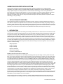
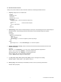
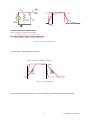
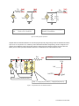
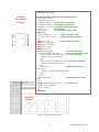
tanhc(x,0.5)
tanhc(x,1)
tanhc(x,-0.5)
tanhc(x,-1)
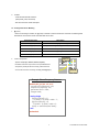
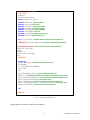
analog function real tanhc;
input x,c; real x,c;
tanhc = tanh( c==0? x : c>0?
x*(1+c/3*x*x) :
x*pow(1-c*x*x,-0.3333) );
endfunction
analog function real ftanhc;
input x,gain,ios,lo,hi,c; real x,gain,ios,lo,hi,c,dv;
begin
dv=(hi-lo)/2;
ftanhc = lo+dv*(1+tanhc(gain/dv*(x-ios),c));
end
endfunction
Figure 2 – Using Adjustable Hyperbolic Tangent Smoothing
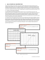
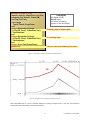
It is important to limit the timestep and frequency where there are fast transitions (<1pS), or high pole frequencies (>1THz)
which will cause very tiny timesteps and long simulation times. Consider realistic rise and fall times (>1nS) and bandwidth
responses (<10MHz), which may help reduce the simulation time. It is possible that just one circuit block with a high
frequency oscillation can have a dramatic impact, pulling the whole simulation down. Timestep and breakpoint controls can
also be helpful improving the waveshaping accuracy. Both time and voltage tolerances can also be used to window-in
thresholds and avoid overstepping sharp nonlinearities. This is explained in detail in the Verilog-A user’s guide.
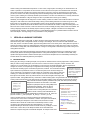
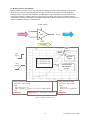
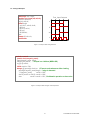
An example of timestep and breakpoint controls:
1.
Input threshold detection: @(cross(expression, direction, time_tolerance, voltage_tolerance)) statement;
2.
DC state & transient edge: @(above(expression, time_tolerance, voltage_tolerance)) statement;
3.
Output timestep control: @(timer(next_time)) statement; or $bound_step(time_increment);
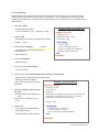
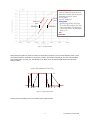
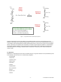
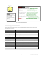
The modeling of a switch is a good example whether to use a sharp or smooth transition. When
a switch is ideal, it could cause trouble working correctly in all conditions. A good practice is to
include realistic effects for impedances and sweep characteristics. Table 1, below, shows some
of the tradeoffs.
RANGE OF SWITCH IMPEDANCE CHANGE
An ideal switch going from zero to infinite
15
Non-convergence
-6
Extreme max & min values (10 to 10 ohms)
+7
Reasonable values (10
SIMULATOR EFFECT
Numerical problems
to 1 ohm)
Efficient evaluation
-12
Simulator default (GMIN = 10 )
Roff <= 1012 ohms
Numerical limit: GMAX = GMIN * 1014
Ron >= 0.01 ohms
SWITCH SWEEP IMPEDANCE BETWEEN LEVELS
Step resistance change
Non-convergence
Linear transfer function (R vs. Vcontrol)
Center = Roff/2
Logarithmic or Log-Cubic function
Center = sqrt(Ron * Roff)
Table 1 – Switch Impedances vs. Simulator Effects
9
PLATFORM APPLICATION NOTE