1
matter of writing a few mathematical expressions. In other cases, it might require curve fitting of non-linear behavior in all
modes of operation. Look-up tables can also be used. The end result is a close replica of the transistor-level circuit block,
which can be used with confidence and reused in other designs. Over time, commonly used blocks that go through this
process can create a reuse library that will greatly enhance simulating designs that otherwise would take longer. The one
common goal in modeling is to eventually simulate top-level behavior. The other is to determine if it is correctly wired and if it
works. Top-level simulations of large IC designs are often not possible without some type of modeling.
Admittedly, most integrated circuit designers do not like modeling. It takes some skill to write models and there is no time for
designers to write models. Some think model writing is boring or that modeling will never be accurate enough to use. But
these points are only partially true. In the initial design phases, second and third order effects, especially from layout
parastics, are not needed for functional simulations. These can be added later as needed. To really do modeling well, it will
take some time to master. However, to learn the basics and to reuse and adapt previously written models is not difficult. The
Verilog-A language constructs are basically simple to follow by example. A designer can extend a set of design aids
tremendously with modeling. And because Verilog-A is a standardized language, it is portable between simulators and can
have wide adoption. Learning Verilog-A is very worthwhile for many designers.
3
VERILOG-A LANGUAGE OVERVIEW
Verilog-A was derived from Verilog HDL in 1996 by the Open Verilog International (OVI) organization, and was later
extended to Verilog-AMS. Verilog-AMS is based on Verilog-A and Verilog-D, which are covered in IEEE standards 13641995. OVI, which is now called Accellera, approved Verilog-AMS version 2.0 in January 2000. Verilog-AMS is a superset of
Verilog-D and Verilog-A and a true mixed-language, where both are written into a model. Many of the Verilog-A constructs
are the same in Verilog-AMS, with minimal differences. Verilog-D in Verilog-AMS is extended to support both Verilog-A and
Verilog-AMS connections.
Verilog-AMS is a true mixed-signal language, interacting with the analog and digital sections by an Application Program
Interface (API) between the analog and digital simulators. Verilog-AMS is designed to work well in Incisive-AMS, a fully
capable mixed-signal simulator. Interface elements (IEs) connect the two disciplines and are automatically inserted by the
simulator based on a relationship defined by the discipline.
3.1 LANGUAGE BASICS
Before going into Verilog-A modeling examples, it is important to understand some of the language basics. Verilog-A has the
ability to model a variety of disciplines, the most common of which are electrical, magnetic, thermal, kinematic, and
rotational. You can also define your own disciplines. For the most part, the electrical discipline, which is expressed as
voltages and currents, is used primarily for integrated circuit modeling. Along with disciplines, there
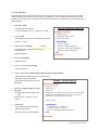
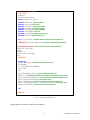
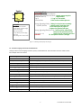
Discipline electrical
are three basic modeling styles: Conservative, Signal-Flow, and Event. The Conservative modeling
domain = electrical;
style includes both a potential and a flow. For an electrical system, these would be voltage and
potential = Voltage;
current, respectively. The Signal-Flow model includes only a potential. This is useful for high-level
flow = Current;
modeling or in cases where there is no need to express a current in an electrical discipline. The
enddiscipline
third style is Event models, which only evaluate events. This is useful in digital, mixed-signal, and
high-level models. Verilog-AMS allows any combination of these modeling styles. Using Kirchhoff’s law, Nodes are defined
as being where branches interconnect and branches are the paths between nodes. Disciplines are described by Natures,
which describe the tolerance (abstol), evaluated units (units), and name (access). Usually,
Nature Voltage
Disciplines and Natures are described in a file called
abstol = 1u;
include “disciplines.h”
disciplines.h (disciplines.vams for Verilog-AMS) which
units = “V”;
include “constants.h”
is included during netlisting. These can also be
access = V;
included in the actual model file. A constants.h
huge = 1e5;
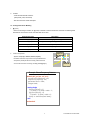
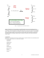
module rlc (a,b);
(constants.vams for Verilog-AMS) file. The constants.h
endnature
electrical a,b;
parameter R=1 exclude 0;
file which carries commonly used mathematical and
parameter C=1;
physical constants is also included. Mathematical constants have an `M_ prefix and
parameter L=1 exclude 0;
physical constant `P_ prefix (examples: `M_TWO_PI = 2π and `P_Q = Q).
Verilog-A modules have pin connections (called ports) and behave like any
component in a circuit, such as a transistor or resistor. The syntax of the model file,
outside of including the disciplines.h and constant.h files, starts with a module
declaration which carries the module name and declared pin names. The pin
connections have declared port directions and disciplines. In IC design, the
discipline will likely be electrical, but there are cases where only a voltage or current
will be used. In other cases, cross-discipline models can be described where
electrical is coupled to magnetic and rotational disciplines. An example of this could
2
branch (a,b) res, cap, ind;
analog begin
I(a,b) <+ idt(V(a,b))/L;
V(res) <+ R*I(res);
I(cap ) <+ C*ddt(V(cap));
end
endmodule;
PLATFORM APPLICATION NOTE