1
Ro
I(out)
I(out)
V(out)
V(out)
Voc/Ro
Voc
Rac
N
I(out)
V(out)
Ro
Voc/Ro
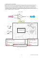
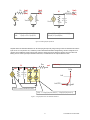
If (Ro>1) I(out) <+ (V(out)-Voc)/Ro;
else
V(out) <+ Voc + I(out)*Ro;
Ro
Co
I(N) <+ (V(N) - Voc)/Ro + Co*ddt(V(N));
I(out,N) <+ V(out,N)/Rac;
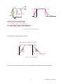
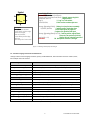
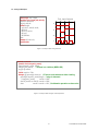
Figure 8 – Modeling Output Impedances
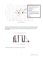
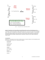
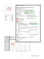
Separate active and saturated resistance can aid in shaping the output. By using a ftanh() function as described can limit the
input current. An `fclip function can, as defined, produce well-defined diode-like voltage limiting, with zero voltage at isat. A
capacitor can be added for simple pole low-pass response. Limiting the current driving the capacitor can act as slew rate
limiting. The DC active region output resistance is Ro+Rac, and saturated and AC output resistance is Rac.
cur
N
res
R
Rac
cap
out
`define fclip(V,isat,dV) isat*exp(4.6*(V)/dV)
lim
fclip
isat
C
isat/100
-dV 0
V
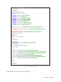
I(cur) <+ ftanh(-Vnom/Ro,Isat,-Isat);
I(lim) <+ `fclip(V(lim)-Voh,Isat,0.1) - `fclip(Vo)V(lim),Isat,0.1);
Figure 9 – Using Separate Active and Saturated Resistance
13
PLATFORM APPLICATION NOTE