1
ROBOT . HEAD to TOE
Product User’s Manual – IFC-MB00
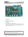
4.2. Main Board (IFC-MB00)
B
A
C
D
E
M
F
F
L
Label
A
B
C
D
E
F
G
K J
Function
5V regulator
Serial cable adaptor (female DB9)
PIC18F2685
Box Header for UIC00A
Orientation marking
Side connector
Header Pin for UART communication
selection
I
H
Label
H
I
J
K
L
M
G
Function
Output LED
Push buttons
Buzzer
Reset Button
Status Indicator LED
Arrow
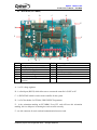
A – is a 5V voltage regulator.
B – is a Serial port (RS232) which allow user to connect the controller’s UART to PC.
C – is PIC18F2685 which is used as main controller for the system.
D – is a 2x5 box header for UIC00A, USB ICSP PIC Programmer.
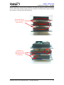
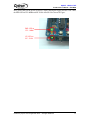
E – is the orientation marking on IFC-MB00. Every IFC card will have this orientation
marking, this is to help user in ensuring the cards are stack correctly.
F – are side connector for stack card and communication between cards.
Created by Cytron Technologies Sdn. Bhd. – All Rights Reserved
8