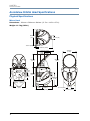
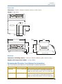
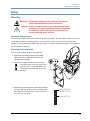
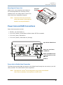
1
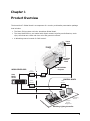
ArenaView
Orbital Head
User Manual
© High End Systems, Inc. 2009, All Rights Reserved
Information and specifications in this document are subject to change without notice.
High End Systems, Inc. assumes no responsibility or liability for any errors or
inaccuracies that may appear in this manual.
Trademarks used in this text: High End Systems, WholeHog III and LithoPatterns are
registered trademarks. The High End Systems globe logo and the Hog logo are
trademarks of High End Systems, Inc. or High End Systems Europe Ltd. Belden is a
registered trademark of Belden, Inc. DLP is trademark of Texas Instruments.
Other trademarks and trade names may be used in this document to refer to either the
entities claiming the marks and names or their products. High End Systems disclaims
any proprietary interest in trademarks and trade names owned by others.
ArenaView Orbital Head System User Manual
P/N 60600261 Version 3
April, 2009
Contacting High End Systems®
US and the Americas
Sales Department:
High End Systems, Inc.
2105 Gracy Farms Lane
Austin, TX 78758 USA
voice:
512.836.2242
fax:
512.837.5290
Customer Service:
High End Systems, Inc.
2105 Gracy Farms Lane
Austin, TX 78758 USA
voice:
800.890.8989
24-hour fax:
512.834.9195
24-hour voice mail: 512.837.3063 or 800.890.8989
World Wide Web:
http://www.highend.com
ii
ArenaView Orbital Head User Manual
Declaration of Conformity
according to ISO/IEC Guide 22 and EN45104
Manufacturer's name:
Distributor's name:
Distributor's address:
High End Systems
High End Systems
2105 Gracy Farms Lane
Austin, TX 78758 USA
Declares that the product:
Product Name: ArenaView Orbital Head System
Product Number: All
Product Options: All
Conforms to the following EEC directives:
73/23/EEC, as amended by 93/68/EEC
89/336/EEC, as amended by 92/31/EEC and 93/68/EEC
Equipment referred to in this declaration of conformity was first manufactured in
compliance with the following standards in 2002:
Orbital Head and Power Supply
EMC:
EN55022:1998 Class A
EN61000-3-2 Class A
EN61000-3-3 Class A
EN50024:1998
EN61000-4-2 Level 3 Class 2
EN61000-4-3 Level 2
EN61000-4-4 Level 2
EN61000-4-5 Level 3
EN61000-4-6 Level 2
EN61000-4-11
Power Supply
Safety:
EN60950:2000
I, the undersigned, hereby declare that the equipment specified above conforms to
the above Directives and Standards.
Ken Hansen
22 May 2003
ArenaView Orbital Head User Manual
iii
Product Modification Warning
High End Systems products are designed and manufactured to meet the requirements of United
States and International safety regulations. Modifications to the product could affect safety and
render the product non-compliant to relevant safety standards.
Mise En Garde Contre La Modification Du Produit: Les produits High End Systems sont
conçus et fabriqués conformément aux exigences des règlements internationaux de sécurité.
Toute modification du produit peut entraîner sa non conformité aux normes de sécurité en
vigueur.
Produktmodifikationswarnung: Design und Herstellung von High End Systems entsprechen
den Anforderungen der U.S. Amerikanischen und internationalen Sicherheitsvorschriften.
Abänderungen dieses Produktes können dessen Sicherheit beeinträchtigen und unter
Umständen gegen die diesbezüglichen Sicherheitsnormen verstoßen.
Avvertenza Sulla Modifica Del Prodotto: I prodotti di High End Systems sono stati
progettati e fabbricati per soddisfare i requisiti delle normative di sicurezza statunitensi ed
internazionali. Qualsiasi modifica al prodotto potrebbe pregiudicare la sicurezza e rendere il
prodotto non conforme agli standard di sicurezza pertinenti.
Advertencia De Modificación Del Producto: Los productos de High End Systems están
diseñados y fabricados para cumplir los requisitos de las reglamentaciones de seguridad de los
Estados Unidos e internacionales. Las modificaciones al producto podrían afectar la seguridad y
dejar al producto fuera de conformidad con las normas de seguridad relevantes.
FCC Information
This equipment has been tested and found to comply with the limits for a Class A digital device,
pursuant to part 15 of the FCC rules. These limits are designed to provide reasonable protection
against harmful interference when the equipment is operated in a commercial environment. This
equipment generates, uses, and can radiate radio frequency energy and, if not installed and
used in accordance with the instruction manual, may cause harmful interference to radio
communications. Operation of this equipment in a residential area is likely to cause harmful
interference, in which case the user will be required to correct the interference at his own
expense.
iv
ArenaView Orbital Head User Manual
Important Safety Information
Instructions pertaining to continued protection against fire, electric shock, and injury to persons
are found in Appendix A. Please read all instructions prior to assembling, mounting, and
operating this equipment.
Important: Informations De Sécurité: Les instructions se rapportant à la protection
permanente contre les incendies, l’électrocution, excessif et aux blessures corporelles se
trouvent dans l’Annexe A. Veuillez lire toutes les instructions avant d’assembler, de monter ou
d’utiliser cet équipement.
Wichtige Sicherheitshinweise: Sicherheitsanleitungen zum Schutz gegen Feuer, elektrischen
Schlag, und Verletzung von Personen finden Sie in Anhang A. Vor der Montage, dem
Zusammenbau und der Intbetriebnahme dieses Geräts alle Anleitungen sorgfältig durchlesen.
Informazioni Importanti Di Sicurezza: Le istruzioni sulla protezione da incendi,
folgorazione, e infortuni sono contenute nell’appendice A. Si prega di leggere tutte le istruzioni
prima di assemblare, montare e azionare l’apparecchiatura.
Informacion Importante De Seguridad: En el Apéndice A se encuentran instrucciones sobre
protección continua contra incendios, descarga eléctrica, y lesiones personales. Lea, por favor,
todas las instrucciones antes del ensamblaje, montaje y operación de este equipo.
Symbols
The following international caution and warning symbols appear in margins throughout this
manual to highlight messages.
Caution:
Warning:
This symbol appears adjacent to Caution messages. Not
heeding these messages could result in personal injury
and/or damage to equipment.
This symbol appears adjacent to high voltage warning
messages. Not heeding these messages could result in
serious personal injury.
ArenaView Orbital Head User Manual
v
Warranty Information
Limited Warranty: Unless otherwise stated, your product is covered by a one year parts and
labor limited warranty. It is the owner’s responsibility to furnish receipts or invoices for
verification of purchase, date, and dealer or distributor. If purchase date cannot be provided,
date of manufacture will be used to determine warranty period.
Returning an Item Under Warranty for Repair: It is necessary to obtain a Return Material
Authorization (RMA) number from your dealer or point of purchase BEFORE any units are
returned for repair. The manufacturer will make the final determination as to whether or not the
unit is covered by warranty.
Any Product unit or parts returned to High End Systems must be packaged in a suitable manner
to ensure the protection of such Product unit or parts, and such package shall be clearly and
prominently marked to indicate that the package contains returned Product units or parts and
with an RMA number. Accompany all returned Product units or parts with a written explanation
of the alleged problem or malfunction. Ship returned Product units or parts to: 2105 Gracy
Farms Lane, Austin, TX 78758 USA.
Note: Freight Damage Claims are invalid for fixtures shipped in non-factory
boxes and packing materials.
Freight: All shipping will be paid by the purchaser. Items under warranty shall have return
shipping paid by the manufacturer only in the Continental United States. Under no circumstances will freight collect shipments be accepted. Prepaid shipping does not include rush
expediting such as air freight. Air freight can be sent customer collect in the Continental United
States.
REPAIR OR REPLACEMENT AS PROVIDED FOR UNDER THIS WARRANTY IS THE EXCLUSIVE
REMEDY OF THE CONSUMER. HIGH END SYSTEMS, INC. MAKES NO WARRANTIES, EXPRESS OR
IMPLIED, WITH RESPECT TO ANY PRODUCT, AND HIGH END SPECIFICALLY DISCLAIMS ANY
WARRANTY OF MERCHANTABILITY OR FITNESS FOR A PARTICULAR PURPOSE. HIGH END SHALL
NOT BE LIABLE FOR ANY INDIRECT, INCIDENTAL OR CONSEQUENTIAL DAMAGE, INCLUDING
LOST PROFITS, SUSTAINED OR INCURRED IN CONNECTION WITH ANY PRODUCT OR CAUSED
BY PRODUCT DEFECTS OR THE PARTIAL OR TOTAL FAILURE OF ANY PRODUCT REGARDLESS OF
THE FORM OF ACTION, WHETHER IN CONTRACT, TORT (INCLUDING NEGLIGENCE), STRICT
LIABILITY OR OTHERWISE, AND WHETHER OR NOT SUCH DAMAGE WAS FORESEEN OR
UNFORESEEN.
Warranty is void if the product is misused, damaged, modified in any way, or for unauthorized
repairs or parts. This warranty gives you specific legal rights, and you may also have other
rights which vary from state to state.
vi
ArenaView Orbital Head User Manual
Table of Contents
User Manual ........................................................................................................ i
Contacting High End Systems® ............................................................................ ii
Product Modification Warning ............................................................................... iv
FCC Information ................................................................................................ iv
Important Safety Information ............................................................................... v
Symbols ............................................................................................................ v
Warranty Information ......................................................................................... vi
Chapter 1: Product Overview
ArenaView Orbital Head Features .......................................................................... 2
Related Products and Accessories .......................................................................... 3
ArenaView Orbital Head Specifications ................................................................... 4
Physical Specifications ..................................................................................... 4
Mirror Head ................................................................................................ 4
Power Hub .................................................................................................. 5
Roadcase .................................................................................................... 5
Recommended Projector Lens Options for ArenaView ........................................... 5
Electrical Specifications .................................................................................... 6
Environmental Specifications ............................................................................ 6
Cable and Connector Specifications .................................................................... 6
DMX .......................................................................................................... 6
Mirror Head to Power Hub Connection ............................................................ 7
Chapter 2: Setup and Configuration
Inspecting the Orbital Head System ....................................................................... 9
Hardware ....................................................................................................... 9
Cabling .......................................................................................................... 9
Save All Shipping Materials ............................................................................... 9
Installing Power Cord Caps ................................................................................. 10
Installing a Line Cord Cap - U.K. Only .............................................................. 10
Vatic Fitter Heads Information - Danmark ......................................................... 10
Setup .............................................................................................................. 11
Mounting ...................................................................................................... 11
Hardware Requirements ............................................................................. 11
Mounting the Orbital Head .......................................................................... 11
Mounting the Power Hub ............................................................................. 13
ArenaView Orbital Head User Manual
vii
Power Hub and DMX Connections ........................................................................ 13
Power Hub to Orbital Head Connection ......................................................... 13
DMX Data Connection ................................................................................ 14
Connecting to a DMX512 Link ......................................................................... 14
Required Data Cabling and Connectors ......................................................... 14
Constructing a Terminator .......................................................................... 15
Setting Up a DMX Link ............................................................................... 15
Powering On the System .................................................................................... 16
Before Applying Power ................................................................................... 16
Applying Power ............................................................................................. 16
Verifying/Uploading Power Hub Software .............................................................. 16
Setting a DMX Start Channel .............................................................................. 17
Chapter 3: Operation and Maintenance
The Power Hub Menu Display .............................................................................. 19
Navigational Basics ........................................................................................... 20
Display in Menu Locked Mode ............................................................................. 20
Fixture Software Version ................................................................................ 20
System Configuration Type ............................................................................. 20
DMX Start Channel ........................................................................................ 20
Error Message Display ................................................................................... 20
Unlocking the Menu System ............................................................................... 21
Exiting the Menu System ................................................................................... 21
Menu Map ........................................................................................................ 21
DMX Address Menu ........................................................................................... 23
Setting a DMX Start Channel .......................................................................... 23
Set Parameters Menu ........................................................................................ 23
Factory Default Settings ................................................................................. 23
Display Level ................................................................................................ 24
Lamp Control ................................................................................................ 24
Mirror 2 Quick Path ....................................................................................... 24
Fixture Mode Menu ........................................................................................... 25
Crossloading Fixture Software ......................................................................... 25
Protocol Mode ............................................................................................... 25
Test Options Menu ............................................................................................ 26
Copying the Boot Code .................................................................................. 26
Homing the Fixture ........................................................................................ 26
Self Test Menu .............................................................................................. 27
viii
ArenaView Orbital Head User Manual
Information Menu
............................................................................................ 27
Channels Needed .......................................................................................... 27
Display Errors ............................................................................................... 27
DMX Values Menu .......................................................................................... 28
Fixture Hours ................................................................................................ 28
Fixture Hours Reset ....................................................................................... 28
Module Version Menu ..................................................................................... 29
Next DMX Channel ........................................................................................ 29
Sensor Status Menu ....................................................................................... 29
Software Version ........................................................................................... 29
Unique Number ............................................................................................. 29
Power Hub Maintenance ..................................................................................... 30
Replacing the Power Hub Fuse ........................................................................ 30
Replacement Parts ........................................................................................ 30
Cleaning the Mirrors ...................................................................................... 30
Chapter 4: DMX Programming
DMX Programming Terminology .......................................................................... 31
DMX Parameters ............................................................................................... 31
ArenaView Orbital Head Positioning .................................................................. 31
Focus .......................................................................................................... 31
Zoom .......................................................................................................... 31
Shutter ........................................................................................................ 31
MSpeed (Motor Speed) ................................................................................... 32
Control Function ............................................................................................ 32
DMX Protocol Table ........................................................................................... 33
Chapter A: MSpeed Conversion Table.................................................... 35
Chapter B: Safety Information ................................................................ 37
Appendice B: Importantes Informations Sur La Sécurité ..................................... 38
Anhang B: Wichtige Hinweise Für Ihre Sicherheit ............................................... 39
Apéndice B: Información Importante De Seguridad ............................................ 40
Appendice B: Importanti Informazioni Di Sicurezza ............................................ 41
Vigtig Sikkerhedsinformation .......................................................................... 41
ArenaView Orbital Head User Manual
ix
x
ArenaView Orbital Head User Manual
Chapter 1:
Product Overview
The ArenaView™ Orbital Head is a component of a turnkey multimedia presentation package
that includes:
• The Barco FLM projector with the ArenaView Orbital Head.
• The Axon Media Server, pre-loaded with digital content including media libraries, stock
clips, stills that can create real time color and geometric effects.
• A Wholehog control console for DMX control.
Power
Hub
TRUSS
ArenaView
Orbital
Head
MEDIA SERVER AREA
Barco FLM R22+
Projector
Video
Extender
Axon
Media
Server
Video
Extender
AXON
Video
Extender
CONTROL BOOTH
Video
Extender
Programming
Monitor
Laptop for
Content
Management
Wholehog Lighting Controller
ArenaView Orbital Head User Manual
1
CHAPTER 1
Product Overview
The ArenaView Orbital Head from High End Systems® utilizes a moving mirror head mounted on
the front of a Barco FLM series* projector to position a projected image anywhere in threedimensional space. A power hub component mounts separately to allow DMX control of the
Orbital Head movement and projector shutter, lamp, focus and zoom. The Arenaview system
incorporates the Axon Media Server to provide real-time video rendering.
Additional
Note: The Arenaview Orbital Head functions best with projectors having a
4:3 aspect ratio. The projected image will be cropped with FLM HD
projectors having lower throw ratio lenses.
The ArenaView Orbital Head ships with:
• A Periscopic Dual-Mirror Orbital Head
• A bracket kit for mounting the Orbital Head to a Barco FLM series projector
• A Power Hub with truss mounting bracket
• Cabling for XLR and power connections
The ArenaView Orbital Head customized roadcase is available separately as part number
56010001.
ArenaView Orbital Head Features
• USITT DMX512 compatible control
• High resolution stepper motors (180,000 steps per revolution) to provide smooth, 16-bit DMX
movement control
• Quick Path feature to allow faster position changes in Mirror 2 movement
• Barco FLM projector mounting bracket
• Universal variable 100–230V power input
• On-board menu system with dot matrix display
2
ArenaView Orbital Head User Manual
CHAPTER 1
Product Overview
Related Products and Accessories
The following table lists related products and accessories available for the ArenaView Orbital
Head from your High End dealer/distributor. For more information, contact your High End
Systems dealer/distributor or see “Contacting High End Systems” on page ii.
Part Description
Part Number
Additional Power Hub
56040053
Outer Mirror
80180006
Inner Mirror
80180007
Galvanized safety cable
12040001
Cheeseborough clamp
55040014
Male 5-pin DMX terminator
90404039
Heavy duty 5-pin XLR cable (10’)
55050017
Heavy duty 5-pin XLR cable (25’)
55050018
Heavy duty 5-pin XLR cable (50’)
55050019
Heavy duty 5-pin XLR cable (100’)
55050020
4-pin XLR Modular Link cable
90409125
DMX Module for Barco FLM projector
R9854549
Axon Media Server
76020002
Wholehog 3 lighting console
61020001
ArenaView Orbital Head User Manual
3
CHAPTER 1
Product Overview
ArenaView Orbital Head Specifications
Physical Specifications
Mirror Head
Dimensions: 349 mm x 369 mm x 686 mm (13.7in x 14.5in x 27in).
Weight: 12.7 kg (28 lbs)
348.6mm
(13.7in)
76.7mm (3in)
15.8mm (.62in)
369.4mm (14.5in)
292.2mm (11.5in)
97mm
(3.8in)
285.2mm
(11.2in)
176mm
(6.9in)
685.8mm
(27in)
45°
109mm
(4.3in)
116mm
(4.6in)
386mm
15.2in)
299.7mm
(11.8in)
121.4mm
(4.8in)
400.6mm
(15.8in)
289.9mm
(11.4in)
109.5mm 109.5mm
(4.3in)
(4.3in)
30°
249.6mm
(9.8in)
4
162.7mm
(6.4in)
364mm
(14.3in)
45°
81.3mm (3.2in)
249.6mm (9.8in)
ArenaView Orbital Head User Manual
CHAPTER 1
Product Overview
Power Hub
Dimensions: 276 mm x 301mm x 120mm (10.9in x 11.8in x 4.7in).
Weight: 2.3 kg (5 lbs)
13.2 mm
(.5 in)
75 mm
(3 in)
40 mm
(1.6 in)
60 mm
(2.4 in)
276.4 mm (10.9 in)
52 mm
(2.1 in)
150 mm
(5.9 in)
151 mm
(5.9 in)
119 mm
(4.7 in)
15.5 mm (.6 in)
300.7 mm (11.8 in)
Roadcase
Dimensions (including casters): 1150 mm x 622 mm x 660 mm (45 in x 24.5 in x 26 in)
Weight (with components loaded): 71.7 kg (158 lbs)
Recommended Projector Lens Options for ArenaView
One of the following lens options are recommended for optimal performance:
Barco Part #
Lens
Description
R9862040
2.5-4.5:1 Zoom Lens When used with the SXGA+ products, this lens has
a 2.5-4.5:1 throw ratio. If used with the DW3K or
DW6K, the lens will provide a 2.8-5.0:1 throw ratio.
R9862999
4.5-7.3:1 Zoom Lens When used with the SXGA+ products, this lens has
a 4.5-7.3:1 throw ratio. If used with the DW3K or
DW6K, the lens will provide a 5.0-8.0:1 throw ratio.
ArenaView Orbital Head User Manual
5
CHAPTER 1
Product Overview
Electrical Specifications
The following electrical specifications apply to the Power Hub component of the ArenaView
Orbital Head System.
Warning: Class I equipment – This equipment must be earthed
Universal Input from 100 – 230 VAC, (50 – 60 Hz)
Rated power: 100 W
Fuse: Power supply output fuse: 2.5 A, 250 V slow blow only.
Environmental Specifications
Maximum ambient temperature (Ta): 40o C
IP Rating: IP 20
Cable and Connector Specifications
DMX
Cables: Belden 9841 or equivalent (meets specifications for EIA RS-485 applications) with the
following characteristics:
• 4-conductor two twisted pairs plus a shield
• Maximum capacitance between conductors: 30 pF/ft
• Maximum capacitance between conductor and shield: 55 pF/ft
• Maximum resistance: 20 Ohm/100 ft
• Nominal impedance: 100–140 Ohm
Connectors: Two 5-pin male and female XLR connectors:
• Pin 1 Ground
• Pin 2 Data–
• Pin 3 Data+
• Pin 4 Secondary data–
• Pin 5 Secondary data+
Terminator: 5-pin male XLR connector with a 120 Ohm terminating resistor fitted between pins
2 and 3.
6
ArenaView Orbital Head User Manual
CHAPTER 1
Product Overview
Mirror Head to Power Hub Connection
Cable: 4–conductor, 1.5 mm2 with a maximum length of 2 meters.
Connectors: 4-pin male and female XLR connectors:
• Pin 1 Ground
• Pin 2 Data Complement
• Pin 3 Data True
• Pin 4 +40V
ArenaView Orbital Head User Manual
7
CHAPTER 1
Product Overview
8
ArenaView Orbital Head User Manual
Chapter 2:
Setup and Configuration
This chapter outlines installation and configuration of the Orbital Head component
of the ArenaView Orbital Head system.
Inspecting the Orbital Head System
The following components are shipped as the ArenaView Orbital Head system:
Hardware
• Orbital Head fixture
• Power Hub
• Mirrorhead mounting bracket for a Barco FLM series projector
Cabling
• 4-pin XLR Power hub cable
• RS 232 cable
• US power cable
• European power cable
Unpack all components and verify that it is undamaged. Inspect both the outside of the
components for physical damage and the optical surfaces of the Orbital Head. If the product is
damaged or there are items missing, notify both the shipping agent and your sales agent
immediately.
Save All Shipping Materials
Do not discard shipping materials. Packing materials are specifically designed to protect the
product during transport.
High End Systems® assumes no responsibility for products that are damaged during transport.
Return a product for repair in its original shipping carton and packing materials.
Before sending anything to the factory, call your High End Systems dealer/distributor for a
Return Material Authorization (RMA) number. The factory cannot accept any goods shipped
without an RMA number.
ArenaView Orbital Head User Manual
9
CHAPTER 2
Setup and Configuration
Installing Power Cord Caps
The Power Hub for the ArenaView Orbital Head system may ship without an attached power cord
cap. Different locations (even within the same country) may require a different power cord cap
to connect the fixture to a power outlet.
Because of the variety of power cord caps used worldwide, High End Systems, Inc. cannot make
specific recommendations for the power cord cap.
Contact a local authority for the type of power cord cap needed. When installing the power cord
cap, note that the cores in the mains lead are colored in accordance with the following code:
• green and yellow = earth
• blue = neutral
• brown = line
Warning: Class 1 equipment - This equipment must be earthed.
Installing a Line Cord Cap - U.K. Only
In the United Kingdom, the colours of the cores in the mains lead of this equipment may not
correspond with the coloured markings identifying the terminals in the fixture’s plug. Therefore,
install a line cord cap in accordance with the following code:
• The core which is coloured green and yellow must be connected to the plug terminal which is
, or coloured green, or green and
marked with the letter “E,” or by the earth symbol
yellow.
• The core which is coloured blue must be connected to the terminal which is marked with the
letter “N” or coloured black.
• The core which is coloured brown must be connected to the terminal which is marked with the
letter “L” or coloured red.
Vatic Fitter Heads Information - Danmark
Advarsel: Beskyttelse mod elektrisk chock.
Vigtigt!
Lederne med gul/groen isolation maa kun tilsluttes en klemme maerket
eller
10
ArenaView Orbital Head User Manual
CHAPTER 2
Setup and Configuration
Setup
Mounting
Warnings: Equipment suitable for dry locations only. Do not
expose this equipment to rain or moisture.
Caution: If mirror surface needs to be cleaned during setup
procedure, use only a mild glass cleaner (containing
no ammonia) and a soft, lint-free cotton cloth to
avoid scratching mirror surface.
Hardware Requirements
To mount the Orbital Head onto a Barco FLM series projector, you will need to select a lens and
install the provided mounting bracket. You must select a lens from the recommended lens
options to avoid impeding Orbital Head movement, (see Recommended Projector Lens Options
for ArenaView on page 5).
Mounting the Orbital Head
To mount the Orbital Head to the projector:
1. Attach the mounting plate to the Orbital
Head using four knobs with M6 lock and
flat washers provided.
2. Remove the large closed eye-bolt and the
interlocking pin from the front of the
projector top. Thread standoffs into
the projector, positioning the longer
one at the front.
3. Attach the mounting plate to the lower bracket
with two M6 socket cap screws. Position them
according to the label in the correct holes for
the lens you are using.
Lens #1 (2.8-4.5:1)
Lens #3 (7.5-11.5:1)
Lens #2 (4.5-7.5:1)
ArenaView Orbital Head User Manual
11
CHAPTER 2
Setup and Configuration
4. Attach the mounting plate to the upper bracket using five M6 socket cap screws.
UPPER PLATE
STANDOFFS
LOWER PLATE
SMALL SAFETY CABLE
LARGE SAFETY CABLE
5. Loosen the rail support from the lower bracket.
6. Hook the lower bracket over the lifting bar and tilt
the whole assembly until it is positioned over the
standoffs.
Lens #2 (4.5-7.5:1)
Note: The standoffs should be aligned with the
correct holes in the upper bracket for the
lens you are using.
Lens #1 (2.8-4.5:1)
Lens #3 (7.5-11.5:1)
7. Secure the upper bracket to
the standoffs with M10 flat
washers and hex nuts.
8. Secure the rail support to the lower bracket with two M6 socket cap screws.
9. Attach the large safety cable to the lifting bar and the Orbital Head Mounting Bracket and
clip the loose end of the small safety cable to the Orbital Head.
Note: A hole is available in the upper plate of the mounting brack for
re-installing the closed eye bolt if needed.
12
ArenaView Orbital Head User Manual
CHAPTER 2
Setup and Configuration
Mounting the Power Hub
Mounting
Bracket
Attach one or two cheeseborough clamps to
the mounting bracket for mounting on any
standard truss. Use safety cable to secure the
Power Hub to an independent support.
Note: The Power Hub must be located
within two meters of the projector
head for correct performance.
Power Hub and DMX Connections
Power Hub connections include:
• IEC320: 100-130V Power in
• 4-Pin XLR (female): Power/Data to Orbital Head: IEC320 receptacle
• 5-Pin XLR (male): DMX data in
• 5-Pin XLR (female): DMX data out (through)
4-pin XLR to Orbital Head
4OV, 2.0 A
DC
Data out to next fixture
on DMX link
Data in from DMX console
or previous device on the
DMX link
Power In
Power Hub to Orbital Head Connection
The Power Hub provides data and power to the Orbital Head through the two meter, 4-pin XLR
cable provided. This cable should not be lengthened.
Note: The cable has 1.5 mm2 cores designed to carry power to the Orbital
Head. Do not substitute a microphone or similar cable.
ArenaView Orbital Head User Manual
13
CHAPTER 2
Setup and Configuration
DMX Data Connection
The Power Hub connects to a DMX controller or another fixture on a DMX 512 link using a 5-pin
DMX512 data connector compliant with the USITT standard. See Connecting to a DMX512 Link
for detailed instructions on data cable construction and connection.
Connecting to a DMX512 Link
The Orbital Head System can be controlled with a DMX console on a DMX512 link for real time
image manipulation and positioning.
The Orbital Head System can also operate without the server as a standalone fixture on a DMX
link to position projector output utilizing the moving Orbital Head.
Required Data Cabling and Connectors
To link one or more fixtures to a controller and/or to each other, obtain data cabling. Cabling
can be purchased from High End Systems® (see Related Products and Accessories on page 3)
or constructed according to the following specifications.
High End Systems® recommends data-grade cable. Data-grade cable is designed to carry a
high-quality signal with less susceptibility to electromagnetic interference.
DMX Data Cables: Use Belden® 9842 or equivalent (meets specifications for EIA RS-485
applications) data cables with the following characteristics:
• Two twisted pairs (4-conductors) plus a shield
• Maximum capacitance between conductors: <15 pF/ft.
• Maximum capacitance between conductor and shield: 55 pF/ft.
• Maximum resistance: 20
/1000 ft.
• Nominal impedance: 120
Cable Connectors: The Power Hub accepts 5-pin XLR cable connectors. Cabling must have a
male XLR connector on one end of the cable and a female XLR connector on the other end.
Pin one is the common (cable shield), pin two is the data complement (negative), pin three is
the data true (positive). Pins four and five are not used, but they allow a secondary data link to
pass through the fixture, (see ).
Test each cable with a voltage/ohm meter (VOM) to verify correct polarity and to make sure
that the negative and positive pins are not grounded or shorted to the shield or to each other.
Caution: Do not connect anything to the ground lug on the XLR
connectors. Do not connect or allow contact between the
common (cable shield) and the fixture’s chassis ground.
Grounding the common could cause a ground loop and/or
erratic behavior.
14
ArenaView Orbital Head User Manual
CHAPTER 2
Setup and Configuration
Grounding lug (inside XLR shell)
Common
(cable shield)
Positive
(data true)
Negative
Negative
(data complement)
(data complement)
Positive
(data true)
Positive
(data true)
Common
(cable shield)
Negative
(data complement)
Male XLR Connector
Negative
(data complement)
Positive
(data true)
Female XLR Connector
XLR 5-pin connector cable
Constructing a Terminator
Install a 120 ohm, 1/4 watt (minimum) terminator in the fixture’s Data Out (female) cable
connector in the last fixture on each DMX link. A terminator on the last fixture of the link
prevents data reflection, which can corrupt the data communication on the link.
Purchase a terminator from a High End Systems dealer/distributor (see Related Products and
Accessories on page 3), or follow the instructions below to construct a terminator.
To construct a terminator:
1. Disassemble a male 5-pin XLR connector.
2. Solder a 120 ohm resistor, minimum of 1/4 watt,
between pins two and three (see 3.).
3. Reassemble the XLR connector
0Ω
12
1
2
3
5
4
Data cable terminator
Setting Up a DMX Link
Each fixture on a DMX link has a data in and a data out (through) connection. The ArenaView
Orbital Head functions as a fixture on the link using six channels to control mirror movement
and the power hub function. The controller sends commands through the Power Hub to control
mirror movement and position an image from the projector. The ArenaView Orbital Head can be
daisy-chained to other automated lighting fixtures on the link.
Note: The Barco FLM series projector requires 10 DMX channels to control
projector functions.
To set up a DMX link:
1. Connect the male XLR connector of a DMX data cable to the controller’s DMX ‘data out’
connector.
2. Connect the Data cable’s female XLR connector to the ‘data in’ connector of the first (or
next) device on the DMX link. This connection is on the Orbital Head power hub.
ArenaView Orbital Head User Manual
15
CHAPTER 2
Setup and Configuration
3. Continue linking the remaining fixtures connecting a cable from the ‘data out’ (data thru)
connector of each fixture to the ‘data in’ connector of the next device on the link.
4. Connect a male terminator to the ‘data out’ connector of the last fixture in the link.
Powering On the System
Warnings: Connect this equipment only to a branch circuit having a
maximum overload protection of 20 A.
The Mirror Head moves under remote control, and is
designed for use by proficient technicians in a professional
environment.
Caution: Do not power on the fixture until verifying that the line cord
cap is suitable for the power source in your location.
Keep hands free from the Mirror Head when powering up
the system to avoid a pinching hazard as the Mirror Head
begins to move during automatic homing.
Before Applying Power
• Manually rotate the Mirror Head, checking that it can move freely on both axes without
hitting the projector or any rigging hardware.
• Ensure that all cables, set pieces etc. are clear of the equipment.
• Keep all clothing and body parts clear of the equipment.
• Ensure that the equipment may not be accessed by the public or unqualified persons.
Applying Power
Caution: Keep hands free from the Mirror Head when powering up
the system to avoid a pinching hazard as the Mirror Head
begins to move during automatic homing.
To apply power, connect the appropriate Power Hub line cord into your power source. For more
information on attaching a linecord, see Installing Power Cord Caps on page 10.
Once connected to power, the Orbital Head will initialize (home). During this process, both
mirrors on the Mirror Head rotate to locate end stops and verify that the fixture is operating
correctly.
Verifying/Uploading Power Hub Software
Check the Power Hub display in the Menu Locked mode to identify the software version loaded
on that fixture. Verify that the version displayed by the fixture is the latest available. The latest
software for the ArenaView Orbital Head is available in the support section of the High End
Systems web site (www.highend.com/support). There are two ways to upload new software
to the ArenaView Orbital Head system:
16
ArenaView Orbital Head User Manual
CHAPTER 2
Setup and Configuration
1. Attach a High End Systems Upload Dongle to your computer and upload the software to
your ArenaView Orbital Head system using WinUpload software.
WinUpload software requires a computer running Microsoft® Windows® 95, 98, ME, XP, or
2000 operating system. To Install the WinUpload Software, create a WinUpload folder on
your hard drive. Download the Upload Module from www.highend.com/support page for
your product and copy the WinUpload.exe and inpout32.dll files into the folder on your hard
drive.
2. Crossload software from one fixture that contains the new software to all other ArenaView
Orbital Head systems on the link, (see Crossloading Fixture Software (XLD) on page 32.
Note: Before you can upload new software, you must disconnect any controllers,
bypass any serial data distributors and/or data line optoisolators, and
bypass or make sure that any fixtures using RS-422 communications. These
devices will block communication with any other ArenaView Orbital Head
fixtures on the link.
Setting a DMX Start Channel
A lighting console uses a start channel to identify the range of channels on a DMX link
associated with a particular fixture. A standard DMX512 link has 512 available channels to
divide among all the devices on the link. The start channel is the first channel in a designated
fixture’s channel range. A fixture must have a unique channel range to respond independently
to controller commands.
To determine a valid start channel for a fixture, first identify the channel range (the number of
consecutive channels a fixture requires) of every fixture on the link. Each Orbital Head System
requires a block of six consecutive channels on a 512-Channel DMX link.
To set the DMX start channel using the Power Hub’s onboard menu system:
1. Press the Menu button to unlock the menu system or to move back up the system to the top
level menus. DM X ADDRESS M ENU is the first menu item at the top level.
2. Press the Enter button to select. The display will show SET DM X START CHANNEL:###.The
display will show the start channel currently assigned to the fixture.
3. Use the up and down arrows on the Navigation button to select a new DMX start channel, if
necessary. The display will flash a new option ready for selection.
Note: The last valid Start channel for a fixture on a DMX link is based on the
channel range required by fixture’s module configuration. The last
valid Start channel for the Orbital Head System 507 (512 –6+1).
The Barco FLM series projector requires 10 DMX channels to control
projector functions.
4. Press the Enter button to accept the new DMX start channel.
Note: If the Enter button is not pressed, the old value will remain selected
after exiting the menu.
ArenaView Orbital Head User Manual
17
CHAPTER 2
Setup and Configuration
For more information on navigating the menu system, see The Power Hub Menu Display on page
19.
18
ArenaView Orbital Head User Manual
Chapter 3:
Operation and Maintenance
This chapter discusses the onboard menu system for the Orbital Head power
hub. For more information on operating the fixture with a controller, consult the
controller documentation.
The Power Hub has an on-board menu system allows you to:
• Set a start channel
• Enable and disable default parameter settings
• View protocol type
• Crossload firmware
• Home the Mirror Head
• Test movement and sensor functions
• View current DMX values for all parameters
• View fixture number, software version, errors, channels needed, and next available DMX
channel.
• Strike and douse the projector lamp
The Power Hub Menu Display
The front panel on the Power Hub component has a dot matrix display and six arrows on
buttons that control navigation for the on-board menu system. The buttons are configured
with the Menu button on the left and the Enter button on the right. The center button
navigates through the current level of menu options [Left and Right] and values available for
the current option [Up and Down].
Alpha numeric display
Menu system buttons
Use left and right arrows to move through
the current menu level options
Use the Menu button (on the left when
viewing the display) to unlock the menu
and move back to the previous menu level
ArenaView Orbital Head User Manual
Use up and down arrows to select
from available value or setting options.
Navigation button
Use the Enter button (on the right when
viewing the display) to select the
currently displayed value or option.
19
CHAPTER 3
Operation and Maintenance
Navigational Basics
1. Unlock the Menu system by pressing the Menu
goes to the 2-line format.
2. Use the left and right arrows
options at the current level.
button for a few seconds until the display
on the 4-way Navigation button to scroll through Menu
3. Stop at the desired menu and press the Enter
be stored unless the Enter button is pressed.
button to select. The new option will not
4. If there is another level of menu choices repeat Steps 2 and 3.
5. At the option or setting menu level, use the up and down arrows on the Navigation
button to scroll to the desired option or setting. The option flashes until the Enter button
is pressed. Pressing the Enter button stores the new value for that option. Pressing the
Menu button returns to the previous menu level without changing the value of an option.
6. Continue pressing the Menu button to move back up levels and exit the menu system.
Display in Menu Locked Mode
The Power Hub display panel gives access to the onboard Menu System. When the Menu
System is in locked mode, the panel displays in large 8-character words designed to be viewed
from a distance. Under normal circumstances, when the display is locked, it cycles between
displaying the fixture’s software version [V##.##], the High End Systems logo, and the fixture’s
DMX Start channel [DMX_C###]. Any errors present are also displayed in an 8-character error
description.
Fixture Software Version
The software version loaded on the system can vary even between units purchased at the
same time. Verifying/Uploading Power Hub Software on page 16 describes the procedures to
ensure that all ArenaView Orbital Head systems on the link are running the latest software.
System Configuration Type
The configuration type indicates the system’s modular setup.
DMX Start Channel
The DMX start channel is the first channel currently assigned to that fixture in its range of
channels on a DMX link. For more information on DMX start channels, see Setting a DMX Start
Channel on page 17.
Error Message Display
Errors are displayed in short 8-character form when the menu system is locked. Unlocked,
menu system’s 2-line format displays more detailed information.
20
ArenaView Orbital Head User Manual
CHAPTER 3
Operation and Maintenance
Unlocking the Menu System
To unlock the menu system, press and hold the Menu button until the display changes to the
2-line format. The menu system is protected against inadvertent menu changes by requiring
the Menu button to be held for a few seconds before allowing entry to the menus. DMX
Address Menu is the first option on the top menu level.
Exiting the Menu System
To exit the menu system, keep pressing the Menu button to back out of each menu level until
the High End Systems logo appears. The word AUTOLOCK will appear briefly on the display to
indicate the fixture’s software is “locking” the display. The display switches back to the large
8-character format and, after a few seconds, begins the standard display for the locked mode
as described above.
Menu Map
Use the following table to navigate the menu options on the Power Hub.
Level 1
Level 2
Level 3
enters /exits Menu System and moves up levels
moves between items on same level. selects
DMX
ADDRESS
MENU
SET DMX START CHANNEL: ###
FACTORY DEFAULT
SETTINGS: ###
DISPLAY LEVEL:
SET
PARAMETERS
MENU
LAMP CONTROL MODE
MIRROR 2 QUICK PATH:
PROTOCOL MODE:
FIXTURE
MODE MENU
CROSSLOAD
FIRMWARE:
ArenaView Orbital Head User Manual
Option/Setting
Description/Notes
scrolls between values
selects
1-512
Selected value becomes the first
DMX value in the range for that
Mirror Head on a DMX 512 link.
ON
Reverts Mirror Head to default setting
OFF
Indicates a factory default has
changed
ON
Turns display on
OFF
Dims Display when menu is locked
AUTOMATIC
Douses Lamp after a 5 minute DMX
data loss
MANUAL
Lamp dousing controlled manually
ON
Allows mirror to take the shortest
path to the selected position
OFF
Disables the Quick-Path feature
STANDARD
Factory default setting
NO
Safe setting
YES
Uploads software to all Orbital Head
devices on the link
21
CHAPTER 3
Operation and Maintenance
Level 1
Level 2
Level 3
enters /exits Menu System and moves up levels
moves between items on same level. selects
HOME FIXTURE:
ON
OFF
COPY BOOT:
SELF TEST
MENU:
CHASSIS
YES
Copies boot code to fixture
MIRROR 1
Performs and displays all self test
functions sequentially in the format:
STEP ## DMX:###
MIRROR 2
OFF
For diagnostic use
Displays absolute position of Mirror 1
MIRROR 2 ENCODER
######
Displays absolute position of Mirror 2
Displays fixture’s unique 10character number
BY CHANNEL
1:### ### ### Displays current values for Channels
4:### ### ### 001– 512 and 6 DMX values/screen.
The number at the beginning of each
7: ### ### ### line indicates the first channel with a
10:### ### ###
value displayed on that line.
Displays fixture operation time in
hours:minutes
FIXTURE HOURS
FIXTURE HOURS RESET:
INFORMATION SOFTWARE VERSION:
MENU
MODULE VERSION MENU
NO
Default “safe” setting
YES
Press Enter for 5 seconds to reset
fixture hours to 0
V ##.##.###
Major.Minor.Build
MIRROR 1
HW:#
SW:#
Displays the Hardware and Software
MIRROR 2
versions for each logic board in the
HW:#
SW:#
fixture. Displays NOT AVAILABLE if a
RS232
board does not exist in that position.
INTERFACE
HW:#
SW:#
DISPLAY
NOT
AVAILABLE
DISPLAY
ERRORS
MENU
22
Tests the display function
MIRROR 1 ENCODER
####
UNIQUE NUMBER
##########
DMX VALUES
MENU
Tests projector lamp function
Safe position: no action when
selected
CODE MENU
SENSOR
STATUS
MENU
Homes the Mirror Head
NO
ON
DISPLAY TEST
Description/Notes
scrolls between values
selects
ALL
LAMP STATE
TEST
OPTIONS
MENU
Option/Setting
XXXXXXXXXXXXXXX
XXXXXXXXXXXXXXX
Fixture is communicating with the
board if you are viewing the display
Scrolls through errors displayed in 2line, 16-character format
CHANNELS
NEEDED:
##
Displays channel range for current
Mirror Head configuration
NEXT DMX
CHANNEL:
##
(Current start channel + channels
needed+1)
ArenaView Orbital Head User Manual
CHAPTER 3
Operation and Maintenance
DMX Address Menu
DMX Address is the top level menu selection used to set the fixture’s DMX start channel. Use
this menu option, to change the existing DMX start channel to another DMX start channel.
Setting a DMX Start Channel
To set the DMX start channel on the Power Hub:
1. Press the Menu button to unlock the menu system or to move back up the system to the
top level menus. DMX ADDRESS MENU is the first menu item at the top level.
1. Press the Enter button to select. The display will show SET DMX START CHANNEL:###.The
display will show the start channel currently assigned to the fixture.
2. Use the up and down arrows on the Navigation button to select a new DMX start channel,
if necessary. The display will flash a new option ready for selection.
Note: The last valid Start channel for a fixture is based on the channel range
required by fixture’s module configuration. The last valid Start
channel for the ArenaView Orbital Head System 507 (512 –6+1).
The Barco FLM series projector requires 10 DMX channels to control
projector functions.
3. Press the Enter button to accept the new DMX Start channel.
Note: If the Enter button is not pressed, the old value will remain selected
after exiting the menu.
ArenaView Orbital Head User Manual
23
CHAPTER 3
Operation and Maintenance
Set Parameters Menu
The Set Parameters menu sets all factory options to their default settings or changes the
factory options individually.
Factory Default Settings
If any of the Orbital head default settings are changed, this menu reverts to the OFF option.
The ON option restores all factory defaults.
To check and reset factory defaults:
1. Press the Menu button to unlock the menu system or to move back up the system to the
top level menus.
2. Using the left and right arrows on the Navigation button, scroll through the top level to SET
PARAMETERS MENU and press the Enter button to select.
3. Using the left and right arrows on the Navigation button, scroll to FACTORY DEFAULT SETTINGS.
The current state (ON or OFF) will be displayed.
4. To reinstate the factory defaults if OFF is displayed, use the up and down arrows on the
Navigation button to scroll to ON and press the Enter button to select.
Display Level
Use this menu option to turn the display on or off.
To change display level:
1. Press the Menu button to unlock the menu system or to move back up the system to the
top level menus.
2. Using the left and right arrows on the Navigation button, scroll through the top level to SET
PARAMETERS MENU and press the Enter button to select.
3. Using the left and right arrows on the Navigation button, scroll to the DISPLAY LEVEL.
4. Using the up and down arrows on the Navigation button, choose ON to turn the display on
or OFF to dim the display and press the Enter button to store the option.
Mirror 2 Quick Path
Turning this menu option ON directs the outer mirror to take the shortest path to the selected
position to provide very fast position changes. The default is OFF.
To turn Mirror 2 Quick Path ON:
1. Press the Menu button to unlock the menu system or to move back up the system to the
top level menus.
2. Using the left and right arrows on the Navigation button, scroll through the top level to SET
PARAMETERS MENU and press the Enter button to select.
3. Using the left and right arrows on the Navigation button, scroll to the MIRROR 2 QUICK PATH.
4. Using the up and down arrows on the Navigation button, choose ON and press the Enter
button to store the option.
24
ArenaView Orbital Head User Manual
CHAPTER 3
Operation and Maintenance
Fixture Mode Menu
The Mode menu sets the module and protocol configuration and crossloads software from one
fixture to other Orbital Head System systems on the link.
Crossloading Fixture Software
A fixture running a newer software version can load the new software to all other Orbital Head
Systems on the link using the CROSSLOAD FIRMWARE menu option.
To CROSSLOAD FIRMWARE from one fixture to all Orbital Head System systems on the link:
1. Disconnect or bypass any controllers, serial data distributors, data line optoisolators, and
any fixtures using RS-422 communications (such as Dataflash® AF1000 xenon strobes,
and Intellabeam® fixtures). These devices will block communication between the
crossloading fixture and any other Orbital Head System systems on the link.
2. On the crossloading fixture only, unlock the menu system by pressing and holding down
the Menu button until the extended 2-line display appears indicating the top menu level.
3. Using the left and right arrows on the Navigation button, scroll to the FIXTURE MODE MENU
and press the Enter button to select.
4. Use the left and right arrows on the Navigation button to scroll to CROSSLOAD FIRMWARE.
5. Use the up and down arrows on the Navigation button to scroll to the YES option and press
the Enter button to store. The fixture will upload its software to all other Orbital Head
System systems on the link.
When the crossload has finished successfully, CROSSLOADING COMPLETE will appear briefly in the
display of the crossloading fixture, and all other fixtures will automatically home.
Note: If a new boot code was included with the latest software, the fixture
displays a BOOTDIFF error when it returns to the locked mode of the
menu system. To correct the boot code, copy the new boot code to
each fixture (see “Copying the Boot Code” on page 34-26).
Protocol Mode
This option sets the Protocol to be followed in assigning Start Channels and programming
parameters. STANDARD protocol is the default.
ArenaView Orbital Head User Manual
25
CHAPTER 3
Operation and Maintenance
Test Options Menu
The TEST OPTIONS MENU manually homes the fixture, performs fixture self tests, and stores new
boot code information. Performing fixture self tests may help identify mechanical problems in
the fixture.
Copying the Boot Code
When new software is uploaded to a Orbital Head System, it may contain a new boot code
which must be copied to each fixture. This is apparent if the fixture displays a BOOTDIFF error.
Caution:
Do not remove power from the fixture while
performing a boot copy.
To accept and store the new boot code:
1. Press the Menu button to unlock the menu system or to move back up the system to the
top level menus.
2. Using the left and right arrows on the Navigation button, scroll to the
TEST OPTIONS MENU and press the Enter button to select.
3. Using the left and right arrows on the Navigation button, scroll to the COPY BOOT option and
press the Enter button to select.
4. Use the up and down arrows on the Navigation button to scroll to the YES option and then
press the Enter button to store the command. The fixture will store the new boot code,
then automatically home.
Homing the Fixture
The Orbital Head System automatically homes all its functions whenever it is turned on. This
menu option manually homes the entire fixture.
To remotely home the fixture using a DMX controller, see ArenaView Orbital Head Positioning
on page 31 and Control Function on page 32.
To manually home the fixture:
1. Press the Menu button to unlock the menu system or to move back up the system to the
top level menus.
2. Use the left and right arrows on the Navigation button to scroll to the
TEST OPTIONS MENU and press the Enter button to select.
3. Use the left and right arrows on the Navigation button to scroll to HOME FIXTURE.
4. Press the Enter button to select all to home the orbital head.
26
ArenaView Orbital Head User Manual
CHAPTER 3
Operation and Maintenance
Self Test Menu
This option displays the steps and DMX values generated as the fixture tests the motor
operation of various functions. Self test can be run and viewed on all the fixture parameters
sequentially, or individual parameters.
To access the SELF TEST MENU:
1. Press the Menu button to unlock the menu system or to move back up the system to the
top level menus.
2. Use the left and right arrows on the Navigation button to scroll to the
TEST OPTIONS MENU and press the Enter button to select. The menu displays CHASSIS.
3. Press the Enter button to select.
4. Scroll between MIRROR 1 and MIRROR 2. Press the Enter button to select. The fixture begins
running the selected self test.
ArenaView Orbital Head User Manual
27
CHAPTER 3
Operation and Maintenance
Information Menu
The Information menu displays current fixture information such as sensor status, total fixture
hours, hardware and software versions, DMX errors, and DMX data for any device on the link.
Fixture hours resets are also executed in the Information Menu.
Channels Needed
Use this option to view the number of channels required (channel range) for the fixture’s
specific configuration. The Orbital Head System requires six channels on a DMX link.
Display Errors
This menu option displays current errors in a descriptive 32-character text field.
To DISPLAY ERRORS:
1. Press the Menu button to unlock the menu system or to move back up the system to the
top level menus.
2. Use the left and right arrows on the Navigation button to scroll to the INFORMATION MENU and
press the Enter button to select.
3. Use the left and right arrows on the Navigation button to scroll to the DISPLAY ERRORS menu
option and press the Enter button to select.
4. Use the up and down arrows on the Navigation button to view the list of current errors.
DMX Values Menu
Use this menu option to view current DMX value settings by channel or by parameters. A
Orbital Head System utilizes six channels on a DMX 512 link. Each DMX value is from 0-255.
When viewing DMX value settings by Channel, the Orbital Head System displays current
values for Channels 001– 512 in two lines of three DMX values each per screen. The number
at the beginning of each line indicates the first channel with a value displayed on that line.
When viewing current DMX value settings by the Parameters, the menu displays one
parameter with the DMX value below it per screen. Parameters will change for different
module configurations.
To access the DMX VALUES MENU:
1. Press the Menu button to unlock the menu system or to move back up the system to the
top level menus.
2. Use the left and right arrows on the Navigation button to scroll to the INFORMATION MENU and
press the Enter button to select.
3. Use the left and right arrows on the Navigation button to scroll to the DMX VALUES MENU and
press the Enter button to select.
4. Use the up and down arrows scroll through the channel range. The display shows 6 DMX
values per screen in two lines of 3 values each. The number at the beginning of the line
indicates the channel number corresponding to the first value in that line.
28
ArenaView Orbital Head User Manual
CHAPTER 3
Operation and Maintenance
Fixture Hours
Use this option to view the fixture operation time in hours and minutes.
Fixture Hours Reset
Use this option to reset the fixture operation time to Zero.
To access the FIXTURE HOURS RESET option:
1. Press the Menu button to unlock the menu system or to move back up the system to the
top level menus.
2. Use the left and right arrows on the Navigation button to scroll to the INFORMATION MENU and
press the Enter button to select.
3. Use the left and right arrows on the Navigation button to scroll to the
FIXTURE HOURS RESET option and press the Enter button to select.
4. Use the up and down arrows on the Navigation button to scroll to YES. Press and hold the
Enter button down for 5 seconds to select.
Module Version Menu
This option display’s the hardware and software version number for each logic board in the
fixture as a troubleshooting method for checking communication with the different boards
inthe fixture. Displays NOT AVAILABLE if a board does not exit in that position.
Note: Due to programming functionality, the Display option always
displays NOT AVAILABLE even though communication with the
board is active whenever you can view the display.
Next DMX Channel
Use this option to view the next available DMX start channel on the link following this fixture
and is based on the fixture’s specific configuration. The value displayed uses the formula
(current Start channel + channels needed for this fixture +1).
Sensor Status Menu
The Sensor Status displays the current numeric position of the fixture’s encoders.
To view encoder values:
To access the DMX VALUES MENU:
1. Press the Menu button to unlock the menu system or to move back up the system to the
top level menus.
2. Use the left and right arrows on the Navigation button to scroll to the INFORMATION MENU and
press the Enter button to select.
3. Use the left and right arrows on the Navigation button to scroll to the SENSOR MENU and
press the Enter button to select.
4. Use the left and right arrows on the Navigation button to scroll to view
MIRROR 1 ENCODER or MIRROR 2 ENCODER value.
ArenaView Orbital Head User Manual
29
CHAPTER 3
Operation and Maintenance
Software Version
This option display’s the fixture’s CPU board Software version. The version number is
composed of: V(Major).(Minor).(Build)
Unique Number
Each Orbital Head System has a unique number similar to a serial number. TalkBack™
protocol uses this number to identify a fixture for remote communication over a DMX link. Use
this option to view the fixture’s unique number.
30
ArenaView Orbital Head User Manual
CHAPTER 3
Operation and Maintenance
Power Hub Maintenance
Replacing the Power Hub Fuse
Warning:
Disconnect power before servicing.
This fixture must only be serviced by qualified
personnel. The following information is intended
to assist qualified personnel only.
Replace fuses with the specified type and rating only.
To replace a fuse:
1. Disconnect power to the power supply hub.
2. Remove the three screws on the back of the power supply hub and lift the cover.
3. Locate the fuse on the bridge over the power supply.
4. Replace the Power supply fuse with the following:
Fuse Type and Rating
Manufacturer
High End Systems p/n
2.5 A, 250 V, Slow Blow
Littelfuse 215 02.5
90403027
Replacement Parts
The Orbital Head System has no user-serviceable parts. To return it for servicing, call your
High End Systems dealer/distributor for a Return Material Authorization (RMA) number. High
End Systems cannot accept any goods shipped without an RMA number. For more
information, see “Warranty Information” on page vi.
Cleaning the Mirrors
If the mirrors become dirty, clean them using a mild glass cleaner (containing no ammonia)
and a soft, lint-free cotton cloth.
ArenaView Orbital Head User Manual
31
CHAPTER 3
Operation and Maintenance
32
ArenaView Orbital Head User Manual
Chapter 4:
DMX Programming
DMX Programming Terminology
A Parameter (construct) is a fixture attribute that can be controlled to modify the light beam in
terms of color, beam quality and pattern, intensity, or focus (position). To program fixtures,
DMX values are assigned to each of the fixture’s parameters according to that fixture’s DMX
protocol.
A cue (sometimes referred to as a scene or look depending on the controller used) is one set
of attribute options. Combining cues into sequences, assigning times and synchronizing
fixtures on a link are the basics of show creation. Using a DMX controller, a designer can
control all the fixtures on a link programming an unlimited number of sequences and their
associated timing.
DMX Parameters
ArenaView Orbital Head Positioning
The Mirror1 and Mirror 2 parameters each use two channels for for 16-bit control of the
Orbital Head’s movement direction and speed. The Orbital Head positions the projected image
by independently moving the inner and outer mirrors on the Mirror Head. The inner mirror
(Mirror 1) maps to Pan on DMX control consoles and can move from 0°–270°. The outer
mirror (Mirror 2) maps to Tilt on DMX controllers and has a range of 0°–360°.
MSpeed (Motor Speed)
The MSpeed parameter controls the time required for a motor to complete movement when
changing from one position to another from the longest (DMX value = 0) to the shortest (DMX
value = 65535). MSpeed provides a means for all motors to reach their target position at the
same time, even though each motor may have different distances to travel. MSpeed
movement is extremely smooth because the fixture controls movements independent of DMX
refresh rates. MSpeed provides a balance between quick response and smooth motion with
some lag.
MSpeed times vary from 0.15 seconds to 252.7 seconds. However, when MSpeed is applied to
a parameter, the delay value (length of time allowed for the entire scene) needs to be longer
than the MSpeed value to allow the motors to complete their movement before the end of the
cue.
ArenaView Orbital Head User Manual
31
CHAPTER 4
DMX Programming
An MSpeed value that is longer than the delay value can be used to smoothly change
directions or in creating circles or ballyhoos. It could also produce an undesirable result; for
example, no light output during the scene. For a listing of exact MSpeed times, see MSpeed
Conversion Table on page 35.
Note: The MSpeed option applies to Mirror Head movement speed. Mirror head
speed can also be varied using XFADE time on most DMX consoles. If a
DMX controller cannot perform a smooth 16-bit XFADE, an MSpeed
between 95-99% may greatly improve smoothness.
Control Function
The Control parameter provides access to a number of Power Hub and Projector commands
from the control desk.
Parameter DMX Value
Shutter
0-255
0
32
Control
0-9
Control Option
Safe
Description
Disables all Control settings for normal operation.
10-19
Pan & Tilt MSpeed Off Sets Pan & Tilt MSpeed off.
20-28
Display Off
Sets display to off.
30-38
Display Dim
Dims display characters.
40-48
Display Bright
Brightens the display characters.
60-68
Home All
Remotely homes the Orbital Head pan and tilt functions.
ArenaView Orbital Head User Manual
CHAPTER 4
DMX Programming
DMX Protocol Table
The ArenaView Orbital Head is patched by a DMX controller as an individual fixture on a DMX
link and requires a six-channel range.
Chan
#
Value
dec.
Default
Value
%
Default
Moves inner mirror from 0°–270°
(Maps to Pan)
065535
32768
0-100
50
Moves outer mirror from 0°–360°
(Maps to Tilt)
065535
32768
0-100
50
Function
1
MIrror 1 Coarse
2
Mirror 1 Fine
3
Mirror 2 Coarse
4
Mirror 2 Fine
5
MSpeed
(See Appendix B
for conversion
tables)
Description
Disable
Set from Longest (253.7 sec to
Shortest (0.15 sec)
0
4-255
0
0
1-100
0
The Control channel should not be crossfaded.
No shutter channel requirement.
Safe (normal operation )
Pan & Tilt Mspeed Off
6
Control
0-9
10-19
0
0-4
4-7
0
Set Shutter to 0 to access the following commands
Display Off (send 20 packets)
20-28
8-11
Display Dim (send 20 packets)
30-38
12-15
Display Bright (send 20 packets)
40-48
Home (send 20 packets)
60-68
24-27
Reserved for future use
69-255
28-100
ArenaView Orbital Head User Manual
0
16-19
0
33
CHAPTER 4
DMX Programming
34
ArenaView Orbital Head User Manual
Appendix A: MSpeed Conversion Table
The following table lists the MSpeed (motor) movement times and their corresponding DMX
controller values. If you have a numeric-type controller, use the Value Decimal (dec.) column. If
you have a fader-type controller, use the Value Percentage (%) column. If your controller allows
you to program hex values, use the Value (hex) column.
Time
(sec.)
0.15
0.15
0.17
0.19
0.21
0.25
0.29
0.35
0.41
0.47
0.55
0.63
0.73
0.83
0.94
1.05
1.18
1.31
1.45
1.60
1.75
1.92
2.09
2.27
2.46
2.66
2.86
3.07
3.29
3.52
3.76
4.00
4.25
4.52
4.78
5.06
5.34
5.64
5.94
Value
(dec.)
255
254
253
252
251
250
249
248
247
246
245
244
243
242
241
240
239
238
237
236
235
234
233
232
231
230
229
228
227
226
225
224
223
222
221
220
219
218
217
Value Value
(%) (hex)
100
FF
100
FE
99
FD
99
FC
98
FB
98
FA
98
F9
97
F8
97
F7
96
F6
96
F5
96
F4
95
F3
95
F2
95
F1
94
F0
94
EF
93
EE
93
ED
93
EC
92
EB
92
EA
91
E9
91
E8
91
E7
90
E6
90
E5
89
E4h
89
E3
89
E2
88
E1
88
E0
87
DF
87
DE
87
DD
86
DC
86
DB
85
DA
85
D9
ArenaView Orbital Head User Manual
Time
(sec.)
6.25
6.56
6.89
7.22
7.56
7.91
8.27
8.63
9.00
9.39
9.77
10.17
10.58
10.99
11.41
11.84
12.28
12.72
13.17
13.63
14.10
14.58
15.07
15.56
16.06
16.57
17.09
17.61
18.14
18.68
19.23
19.79
20.36
20.93
21.51
22.10
22.70
23.30
23.92
Value
(dec.)
216
215
214
213
212
211
210
209
208
207
206
205
204
203
202
201
200
199
198
197
196
195
194
193
192
191
190
189
188
187
186
185
184
183
182
181
180
179
178
Value Value
(%) (hex)
85
D8
84
D7
84
D6
84
D5
83
D4
83
D3
82
D2
82
D1
82
D0
81
CF
81
CE
80
CD
80
CC
80
CB
79
CA
79
C9
78
C8
78
C7
78
C6
77
C5
77
C4
76
C3
76
C2
76
C1
75
C0
75
BF
75
BE
74
BD
74
BC
73
BB
73
BA
73
B9
72
B8
72
B7
71
B6
71
B5
71
B4
70
B3
70
B2
Time
(sec.)
24.54
25.17
25.80
26.45
27.10
27.76
28.43
29.11
29.80
30.49
31.19
31.90
32.62
33.34
34.08
34.82
35.57
36.33
37.09
37.87
38.65
39.44
39.44v
40.23
41.04
41.85
42.68
43.50
44.34
45.19
46.04
46.90
47.77
48.65
49.54
50.43
51.33
52.24
53.16
Value
(dec.)
177
176
175
174
173
172
171
170
169
168
167
166
165
164
163
162
161
160
159
158
157
156
156
155
154
153
152
151
150
149
148
147
146
145
144
143
142
141
140
Value Value
(%) (hex)
69
B1
69
B0
69
AF
68
AE
68
AD
67
AC
67
AB
67
AA
66
A9
66
A8
65
A7
65
A6
65
A5
64
A4
64
A3
64
A2
63
A1
63
A0
62
9F
62
9E
62
9D
61
9C
61
9C
61
9B
60
9A
60
99
60
98
59
97
59
96
58
95
58
94
58
93
57
92
57
91
56
90
56
8F
56
8E
55
8D
55
8C
35
APPENDIX A
Time
(sec.)
54.09
55.02
55.96v
56.91
57.87
58.84
59.81
60.79
61.78
62.78
63.79
64.80
65.82
66.85
67.89
68.94
69.99
71.05
72.13
73.20
74.29
75.38
76.49
77.60
78.71
79.84
80.98
82.12
83.27
84.43
85.59
86.77
87.95
89.14
90.34
91.55
92.76
93.98
95.21
96.45
97.70
98.95
100.22
101.49
102.77
104.05
105.35
106.65
107.96
36
Value
(dec.)
139
138
137
136
135
134
133
132
131
130
129
128
127
126
125
124
123
122
121
120
119
118
117
116
115
114
113
112
111
110
109
108
107
106
105
104
103
102
101
100
99
98
97
96
95
94
93
92
91
Value Value
(%) (hex)
55
8h
54
8A
54
89
53
88
53
87
53
86
52
85
52
84
51
83
51
82
51
81
50
80
50
7F
49
7E
49
7D
49
7C
48
7B
48
7A
47
79
47
78
47
77
46
76
46
75
45
74
45
73
45
72
44
71
44
70
44
6F
43
6E
43
6D
42
6C
42
6B
42
6A
41
69
41
68
40
67
40
66
40
65
39
64
39
63
38
62
38
61
38
60
37
5F
37
5E
36
5D
36
5C
36
5B
Time
(sec.)
109.28
110.61
111.94
113.28
114.63
115.99
117.36
118.73
120.12
121.5v
122.91
124.31
125.73
127.15
128.58
130.02
134.39
135.86
137.34
138.82
140.32
141.82
143.33
144.85
146.38
147.92
149.46
151.01
152.57
154.14
155.71
157.30
158.89
160.49
162.09
163.71
165.33
166.96
168.60
170.25
171.91
173.57
175.24
176.92
178.61
180.30
182.01
183.72
185.44
Value
(dec.)
90
89
88
87
86
85
84
83
82
81
80
79
78
77
76
75
72
71
70
69
68
67
66
65
64
63
62
61
60
59
58
57
56
55
54
53
52
51
50
49
48
47
46
45
44
43
42
41
40
Value Value
(%) (hex)
35
5A
35
59
35
58
34
57
34
56
33
55
33
54
33
53
32
52
32
51
31
50
31
4F
31
4E
30
4D
30
4C
29
4B
28
48
28
47
27
46
27
45
27
44
26
43
26
42
25
41
25
40
25
3F
24
3E
24
3D
24
3C
23
3B
23
3A
22
39
22
38
22
37
21
36
21
35
20
34
20
33
20
32
19
31
19
30
18
2F
18
2E
18
2D
17
2C
17
2B
16
2A
16
29
16
28
Time
(sec.)
187.17
188.90
190.65
192.40
194.16
195.92
197.70
199.48
201.28
203.08
204.88
206.70
208.52
210.36
212.19
214.04
215.90
217.76
219.63
221.51
223.40
225.30
227.20
229.11
231.03
232.96
234.90
236.84
238.79
240.75
242.72
244.70
246.68
248.68
250.68
246.68
248.68
250.68
252.68
Value
(dec.)
39
38
37
36
35
34
33
32
31
30
29
28
27
26
25
24
23
22
21
20
19
18
17
16
15
14
13
12
11
10
9
8
7
6
5
7
6
5
4
Value Value
(%) (hex)
15
27
15
26
15
25
14
24
14
23
13
22
13
21
13
20
12
1F
12
1E
11
1D
11
1C
11
1B
10
1A
10
19
9
18
9
17
9
16
8
15
8
14
7
13
7
12
7
11
6
10
6
0F
5
0E
5
0D
5
0C
4
0B
4
0A
4
09
3
08
3
07
2
06
2
05
3
07
2
06
2
05
2
04
ArenaView Orbital Head User Manual
CHAPTER B
Safety Information
Appendix B:
Safety Information
Warning: For Continued Protection Against Fire
1. This equipment for connection to branch circuit having a maximum overload protection of
20 A.
Warning: For Continued Protection Against Electric Shock
1. If this equipment was received without a line cord plug, attach the appropriate line cord
plug according to the following code:
•
brown–line
•
blue–neutral
•
green/yellow–earth
2. As the colours of the cores in the mains lead of this equipment may not correspond with
the coloured markings identifying the terminals in your plug, proceed as follows:
•
the core which is coloured green and yellow must be connected to the terminal in the
plug which is marked with the letter E or by the earth symbol
, or coloured green
or green and yellow.
•
the core which is coloured blue must be connected to the terminal which is marked
with the letter N or coloured black.
•
the core which is coloured brown must be connected to the terminal which is marked
with the letter L or coloured red.
3. Class I equipment. This equipment must be earthed.
4. Equipment suitable for dry locations only. Do not expose this equipment to rain or
moisture.
5. Refer servicing to qualified personnel; no user serviceable parts inside.
ArenaView Orbital Head User Manual
37
CHAPTER B
Safety Information
Appendice B: Importantes Informations Sur La Sécurité
Mise En Garde: Pour Une Protection Permanente Contre Les Incendies
1. Cet appareil de connection au circuit comporte une protection contre les surcharges de 20
A.
Mise En Garde: Pour Une Protection Permanente Contre Les Chocs
Électriques
1. Si cet équipement est livré sans prise de cable, veuillez connecter la prise de cable correcte
selon le code suivant:
•
marron - phase
•
bleu - neutre
•
vert/jaune - terre
2. Débrancher le courant avant de changer les lampes ou d'effectuer des réparations.
3. Cet équipement doit être uniquement utilisé dans des endroits secs. Ne pas l'exposer à la
pluie ou l'humidité.
4. À l'intérieur de l'équipement il n'y a pas de pièces remplaçables par l' utilisateur. Confiez
l'entretien à un personnel qualifié.
5. Equipement de Classe I. Cet équipement doit être mis à la terre.
38
ArenaView Orbital Head User Manual
CHAPTER B
Safety Information
Anhang B: Wichtige Hinweise Für Ihre Sicherheit
Warnung: Zum Schutz Vor Brandgefahr
1. Dieses Gerät darf nur an eine Zweigleitung mit einem Überlastungsschutz von höchstens
20 A angeschlossen werden.
Warnung: Zum Schutz Gegen Gefährliche Körperströme
1. Wenn dieses Gerät ohne einen Netzkabelstecker erhalten wurde, ist der entsprechende
Netzkabelstecker entsprechend dem folgenden Code anzubringen:
•
Braun - Unter Spannung stehend
•
Blau - Neutral
•
Grün/Gelb - Erde
2. Vor dem Austauschen von Lampen oder vor Wartungsarbeiten stets den Netzstecker
ziehen.
3. Diese Geräte sind nur zum Einbau in trockenen Lagen bestimmt und müssen vor Regen
und Feuchtigkeit geschützt werden.
4. Servicearbeiten sollten nur von Fachpersonal ausgeführt werden. Das Gerät enthält keine
wartungsbedürftigen Teile.
5. Dieses Gerät gehört zur Klasse I. Dieses Gerät muß geerdet werden.
ArenaView Orbital Head User Manual
39
CHAPTER B
Safety Information
Apéndice B: Información Importante De Seguridad
Advertencia: Para Protección Continua Contra Incendios
1. Este equipo debe conectarse a un circuito que tenga una protección máxima contra una
sobrecargas de 20 A.
Advertencia: Para La Protección Continua Contra Electrocuciones
1. Si se recibió este equipo sin el conector de alimentacion, monte usted el conector correcto
según ia clave siguente:
•
moreno - vivo
•
azul - neutral
•
verde/amarillo - tierra
2. Desconecte el suministro de energía antes de cambiar lámparas o prestar servicio de
reparación.
3. Este equipo esta disenado para usarce en lugares secos no lo exponga a la lluvia o
humedad.
4. Derive el servicio de reparación de este equipo al personal calificado. El interior no contiene
repuestos que puedan ser reparados por el usuario.
5. Equipo de Clase I. Este equipo debe conectarse a tierra.
40
ArenaView Orbital Head User Manual
CHAPTER B
Safety Information
Appendice B: Importanti Informazioni Di Sicurezza
Avvertenza: Per Prevenire Incendi
1. Questa apparecchiatura e' da collegarsi ad un circuito con una protezione da sovraccarico
massima di 20 ampere.
Avvertenza: Per Prevenire Le Scosse Elettriche
1. Da non montare sopra una superficie infiammabile.
2. Mantenere l' apparecchio a un minimo di 1.0 metri (3.28 piedi) di distanza dai materiali
combustibili.
3. Sostituire i fusibili usando soltanto quelli del tipo e della taratura adatta.
4. Mantenere una distanza minima di 1.0 metri (3.28 piedi) dagli oggetti accesi.
5. Questa apparecchiatura e' da collegarsi ad un circuito con una protezione da sovraccarico
massima di 20 ampere.
Vigtig Sikkerhedsinformation
Advarsel: Beskyttelse mod elektrisk chock.
VIGTIGT! LEDEREN MED GUL/GROEN ISOLATION MAA KUN TILSLUTTES KLEMME MAERKET
ELLER
.
ArenaView Orbital Head User Manual
41
CHAPTER B
Safety Information
42
ArenaView Orbital Head User Manual