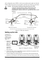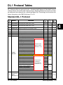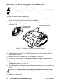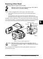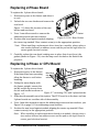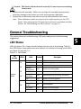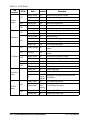
1
User Manual
© High End Systems, Inc. 2004, All Rights Reserved
Information and specifications in this document are subject to change without notice.
High End Systems, Inc. assumes no responsibility or liability for any errors or
inaccuracies that may appear in this manual.
Trademarks used in this text: High End Systems, WholeHog III, Catalyst, the Catalyst
Logo, Dataflash, Intellebeam, and LithoPatterns are registered trademarks; and TalkBack,
the High End Systems globe logo and the Hog logo are trademarks of High End Systems,
Inc. or High End Systems Europe Ltd. Belden is a registered trademark of Belden, Inc.
Mac OS is a trademark of Apple Computer, Inc. registered in the U.S. and in other
countries.
Other trademarks and trade names may be used in this document to refer to either the
entities claiming the marks and names or their products. High End Systems disclaims any
proprietary interest in trademarks and trade names owned by others.
DL.1 User Manual
P/N 60600228 Version 6.0
Printed in the USA
November 2005
DL1 User Manual
i
ii
DL1 User Manual
Contacting High End Systems®
US and the Americas
Sales Department:
High End Systems, Inc.
2105 Gracy Farms Lane
Austin, TX 78758 USA
voice:
512.836.2242
fax:
512.837.5290
Customer Service:
High End Systems, Inc.
2105 Gracy Farms Lane
Austin, TX 78758 USA
voice:
800.890.8989
24-hour fax:
512.834.9195
24-hour voice mail: 512.837.3063 or 800.890.8989
World Wide Web:
http://www.highend.com
DL1 User Manual
iii
Declaration of Conformity
according to ISO/IEC Guide 22 and EN45104
Manufacturer’s name:
High End Systems, Inc.
Distributor’s name:
Distributor’s address:
High End Systems, Inc.
2105 Gracy Farms Lane
Austin, Texas 78758 USA
Declares that the product
Product Name:
DL.1
Product Number: All
Product Options: All
conforms to the following EEC directives:
73/23/EEC, as amended by 93/68/EEC
89/336/EEC, as amended by 92/31/EEC and 93/68/EEC
Equipment referred to in this declaration of conformity was first manufactured in
compliance with the following standards in 2003:
Safety: EN60950:2000
EMC:
EN55022: 1998: Class A ITE
EN61000-3-2
EN61000-3-3
EN55024:1998
EN61000-4-2: Level 3, Class 2
EN61000-4-3: 1995 Level 2 (3V/m)
EN61000-4-4: 1995 Level 2 (1/.5kV)
EN61000-4-5: 1995 Level 3 (2/1kV)
EN61000-4-6: 1965 Level 2 (3Vrms)
EN61000-4-11:1994
USA, Thursday, November 17, 2005
Kenneth Stuart Hansen, Compliance Engineer
iv
DL1 User Manual
Product Modification Warning
High End Systems products are designed and manufactured to meet the
requirements of United States and International safety regulations. Modifications to
the product could affect safety and render the product non-compliant to relevant
safety standards.
Mise En Garde Contre La Modification Du Produit. Les produits High End
Systems sont conçus et fabriqués conformément aux exigences des règlements
internationaux de sécurité. Toute modification du produit peut entraîner sa non
conformité aux normes de sécurité en vigueur.
Produktmodifikationswarnung. Design und Herstellung von High End
Systems entsprechen den Anforderungen der U.S. Amerikanischen und
internationalen Sicherheitsvorschriften. Abänderungen dieses Produktes können
dessen Sicherheit beeinträchtigen und unter Umständen gegen die diesbezüglichen
Sicherheitsnormen verstoßen.
Avvertenza Sulla Modifica Del Prodotto. I prodotti di High End Systems sono
stati progettati e fabbricati per soddisfare i requisiti delle normative di sicurezza
statunitensi ed internazionali. Qualsiasi modifica al prodotto potrebbe pregiudicare
la sicurezza e rendere il prodotto non conforme agli standard di sicurezza pertinenti.
Advertencia De Modificación Del Producto. Los productos de High End
Systems están diseñados y fabricados para cumplir los requisitos de las
reglamentaciones de seguridad de los Estados Unidos e internacionales. Las
modificaciones al producto podrían afectar la seguridad y dejar al producto fuera de
conformidad con las normas de seguridad relevantes.
FCC Information
This equipment has been tested and found to comply with the limits for a Class A
digital device, pursuant to part 15 of the FCC rules. These limits are designed to
provide reasonable protection against harmful interference when the equipment is
operated in a commercial environment. This equipment generates, uses, and can
radiate radio frequency energy and, if not installed and used in accordance with the
instruction manual, may cause harmful interference to radio communications.
Operation of this equipment in a residential area is likely to cause harmful
interference, in which case the user will be required to correct the interference at his
own expense.
DL1 User Manual
v
Important Safety Information
Instructions pertaining to continued protection against fire, electric shock, and injury
to persons are found in Appendix A. Please read all instructions prior to assembling,
mounting, and operating this equipment.
Important: Informations De Sécurité. Les instructions se rapportant à la
protection permanente contre les incendies, l’électrocution, excessif et aux blessures
corporelles se trouvent dans l’Annexe A. Veuillez lire toutes les instructions avant
d’assembler, de monter ou d’utiliser cet équipement.
Wichtige Sicherheitshinweise. Sicherheitsanleitungen zum Schutz gegen
Feuer, elektrischen Schlag, und Verletzung von Personen finden Sie in Anhang A. Vor
der Montage, dem Zusammenbau und der Intbetriebnahme dieses Geräts alle
Anleitungen sorgfältig durchlesen.
Informazioni Importanti Di Sicurezza. Le istruzioni sulla protezione da
incendi, folgorazione, e infortuni sono contenute nell’appendice A. Si prega di
leggere tutte le istruzioni prima di assemblare, montare e azionare l’apparecchiatura.
Informacion Importante De Seguridad. En el Apéndice A se encuentran
instrucciones sobre protección continua contra incendios, descarga eléctrica, y
lesiones personales. Lea, por favor, todas las instrucciones antes del ensamblaje,
montaje y operación de este equipo.
Symbols
The following international caution and warning symbols appear in margins
throughout this manual to highlight messages.
Caution: This symbol appears adjacent to Caution messages. Not heeding
these messages could result in personal injury and/or damage to
equipment.
Warning: This symbol appears adjacent to high voltage warning messages.
Not heeding these messages could result in serious personal
injury.
Minimum focus distance to non-flammable surface. In this case, 1
meter .
Do not mount on a flammable surface.
Equipment surfaces may reach temperatures up to 130° C (266° F).
Allow the fixture to cool before handling.
vi
DL1 User Manual
Patents
This product may use one or more of the following patents:
US 4,392,187; US 4,602,321; US 4,688,161; US 4,701,833; US 4,709,311; US 4,779,176;
US 4,800,474; US 4,962,687; US 4,972,306; US 4,980,806; US 5,010,459; US 5,031,078;
US 5,073,847; US 5,078,039; US 5,186,536; US 5,209,560; US 5,278,742; US 5,282,121;
US 5,307,295; US 5,329,431; US 5,331,822; US 5,367,444; US 5,402,326; US 5,430,629;
US 5,432,691; US 5,454,477; US 5,455,748; US 5,506,762; US 5,515,254; US 5,537,303;
US 5,545,951; US 5,580,164; US 5,590,954; US 5,590,955; US 5,640,061; US 5,647,662;
US 5,665,305; US 5,691,886; US 5,728,994; US 5,758,955; US 5,758,956; US 5,769,527;
US 5,774,273; US 5,798,619; US 5,806,951; US 5,823,661; US 5,825,548; US 5,828,485;
US 5,829,868; US 5,857,768; US 5,882,107; US 5,934,794; US 5,940,204; US 5,945,786;
US 5,953,152; US 5,980,066; US 6,048,080; US 6,327,103; US 6,048,081; US 6,057,958;
US 6,054,816; US 6,126,288; US 6,142,652; US 6,142,653; US 6,172,822; US 6,188,933;
US 6,208,087; US 6,219,093; US 6,220,730; US 6,241,366; US 6,249,091; US 6,255,787;
US 6,256,136; US 6,278,542; US 6,278,545; US 6,288,828; US 6,327,103; US 6,331,756;
US 6,346,783; US 6,421,165; US 6,430,934; US 6,459,217; US 6,466,357; US 6,502,961;
US 6,545,586; US 6,600,270; US 6,635,999; US 6,664,745; US 6,693,392; US 6,719,433;
US 6,783,251; US 6,812,653; US 6,866,390; US 6,866,402; US 6,866,451; US 6,869,193;
US 6,570,348; US 6,575,577; US 6,605,907; US 6,621,239; US 6,8691,239; US 6,930,456;
US 6,955,435; US D347,113; US D350,408; US D359,574; US D360,404; US D365,165;
US D366,712; US D370,080; US D372,550; US D377,338; US D381,740; US D409,771;
EP 0662275; EP 0767398; DE 621495; DE 655144; DE 797503; EP 0475082;
GB 2 043 769 B; GB 2 055 842 B; GB 2 283 808 B; GB 2 290 134 B; GB 2 291 814 B;
GB 2 292 530 B; GB 2 292 896 B; GB 2 294 909 B; GB 2 295 058 B; GB 2 303 203 B;
GB 2 306 887 B; GB 2 307 036 B; GB 2 316 477 B; MR0862-1996; M9,604,224.9
Warranty Information
Limited Warranty. Unless otherwise stated, your product (excluding the lamp) is
covered by a one year parts and labor limited warranty. The lamp carries a 30-day
warranty. It is the owner’s responsibility to furnish receipts or invoices for
verification of purchase, date, and dealer or distributor. If purchase date cannot be
provided, date of manufacture will be used to determine warranty period.
Fog machine warning. Like all high quality video projection units, the DL.1
fixture must be kept protected from excessive amounts of glycol fog, mineral oil, and
smoke. DL.1 incorporates two-stage air filtering to reduce these risks to a minimum;
however, the user must follow these guidelines to ensure continued operation of the
fixture:
•
Air filters (both fixture and projector) should be checked and cleaned on a
regular basis. When used in a closed or fixed environment where fog or haze is
used, we recommend at least a weekly check.
DL1 User Manual
vii
•
Do not situate DL.1 in areas of high fog density such as directly in front of a fog
machine or mineral oil hazer.
•
Minimize the exposure of DL.1 to both glycol fog and mineral oil.
DL.1 is a highly complex and sensitive electro-optical device and care and thought in
how it is used, rigged, and positioned will maximize the product’s life and your
investment.
Failure to follow these guidelines and carry out regular maintenance will void the
warranty.
Returning an Item Under Warranty for Repair. It is necessary to obtain a
Return Material Authorization (RMA) number from your dealer or point of purchase
BEFORE any units are returned for repair. The manufacturer will make the final
determination as to whether or not the unit is covered by warranty.
Any Product unit or parts returned to High End Systems must be packaged in a suitable
manner to ensure the protection of such Product unit or parts, and such package shall be
clearly and prominently marked to indicate that the package contains returned Product
units or parts and with an RMA number. Accompany all returned Product units or parts
with a written explanation of the alleged problem or malfunction. Ship returned Product
units or parts to: 2105 Gracy Farms Lane, Austin, TX 78758 USA.
Note: Freight Damage Claims are invalid for fixtures shipped in non-factory boxes
and packing materials.
Freight. All shipping will be paid by the purchaser. Items under warranty shall have
return shipping paid by the manufacturer only in the Continental United States. Under no
circumstances will freight collect shipments be accepted. Prepaid shipping does not
include rush expediting such as air freight. Air freight can be sent customer collect in the
Continental United States.
REPAIR OR REPLACEMENT AS PROVIDED FOR UNDER THIS WARRANTY IS THE
EXCLUSIVE REMEDY OF THE CONSUMER. HIGH END SYSTEMS, INC. MAKES NO
WARRANTIES, EXPRESS OR IMPLIED, WITH RESPECT TO ANY PRODUCT, AND
HIGH END SPECIFICALLY DISCLAIMS ANY WARRANTY OF MERCHANTABILITY OR
FITNESS FOR A PARTICULAR PURPOSE. HIGH END SHALL NOT BE LIABLE FOR
ANY INDIRECT, INCIDENTAL OR CONSEQUENTIAL DAMAGE, INCLUDING LOST
PROFITS, SUSTAINED OR INCURRED IN CONNECTION WITH ANY PRODUCT OR
CAUSED BY PRODUCT DEFECTS OR THE PARTIAL OR TOTAL FAILURE OF ANY
PRODUCT REGARDLESS OF THE FORM OF ACTION, WHETHER IN CONTRACT,
TORT (INCLUDING NEGLIGENCE), STRICT LIABILITY OR OTHERWISE, AND
WHETHER OR NOT SUCH DAMAGE WAS FORESEEN OR UNFORESEEN.
Warranty is void if the product is misused, damaged, modified in any way, or for
unauthorized repairs or parts. This warranty gives you specific legal rights, and you may
also have other rights which vary from state to state.
viii
DL1 User Manual
What You Should Know About Copyright
Written By Suzy Vaughan Associates for High End Systems
I want to use a film clip from "When Harry Met Sally" in a promotional piece
advertising my services. What do I have to do to be able to do that? First of all, you need
to obtain permission to use the clip from its owners. The clip is considered intellectual
property, just as though it were your car or some software code developed by and
belonging to Microsoft. This is because the U.S. Copyright Act gave creators of literary
works (which include books, films, television programs, art works, still photos and
musical compositions and recordings) the right to sell or license these works and to make
money from them for the period of the copyright.
But what about public domain material? I heard that lots of material is in the public
domain and can be used for free. Once the copyright runs out, the creative work falls into
the public domain and can be used freely by anyone without payment or licensing. If the
work is not public domain, it is considered literary property. The Copyright Act provides
substantial penalties for copyright infringement ranging from $10,000 for accidental
infringement to $250,000 for willful infringement. However, contrary to popular belief,
there really is not that much material in the public domain so this approach will limit you
creatively.
What if I want to use a clip in a public performance? It's not being filmed or taped.
Surely I don't need permission for that? Public gatherings require clearance whenever
copyrighted data is projected to audiences, or for any use other than just personal
viewing. Concerts, tradeshows, industrial shows, parties and raves are all examples of
public performance and permission must be obtained.
Suppose I want to use a still photo or a magazine cover or a television clip? Do I have to
obtain permission for them too? Yes, they are also copyrighted works, whose owners
must grant a license for their usage.
Do I need any other permissions to use this material? In many cases you do. You may
need to obtain permission to use the appearance of actors who appear in the clip as well
as pay the writers and directors of the film that your clip comes from.
What about music? I hear you can use 8 bars for free. 8 bars for free is a fallacy that has
been passed around as a fact for a long period of time. However, it isn't true. Both musical
compositions and records require licensing and payment.
What about High End Systems material included with the Catalyst? Do I have to clear
that? No. High End Systems has worked to provide clearance for the content that is
provided with the Catalyst system. Any materials you received directly from HES with the
purchase of a new Catalyst system have already been properly licensed for your use in
shows and presentations. That does not, however, license you to sell this content
separately from the Catalyst system. Also, please be sure that any new content you obtain
from outside sources is properly cleared for public presentation.
DL1 User Manual
ix
This sounds really difficult and I don't know how to do it? What do I do to properly
license copyrighted material?
You need to consult with a Content Clearing House or with a properly licensed Intellectual
Property Attorney. Content clearinghouses are typically less expensive to work with and
have well established industry relations that can result in cost savings. High End Systems
uses and highly recommends Suzy Vaughan Associates. Suzy Vaughan Associates has 20
years of experience in clearing clips, talent, and music for use in any number of venues.
Their clients include Barbara Streisand, Michael Jackson, and The Emmys among other
shows.
You can obtain more information about Suzy Vaughan Associates' services by calling 818988-5599 or emailing [email protected]. Their website is www.suzyvaughan.com.
Suzy Vaughan is also an attorney specializing in intellectual property issues.
How much does it typically cost to license copyrighted material?
The answer depends entirely on what material you want to use and how you plan to use it.
Prices can range from hundreds of dollars for photography content to thousands of
dollars for a highly desirable film/video clip. Since price is content-sensitive, the best
thing to do is to contact a clearinghouse like Suzy Vaughan Associates and let them find
out for you.
x
DL1 User Manual
Table of Contents
Contacting High End Systems® ................................................................................................... -ii
Product Modification Warning .................................................................................................... -iv
FCC Information ........................................................................................................................... -iv
Important Safety Information ....................................................................................................... -v
Symbols .......................................................................................................................................... -v
Patents ........................................................................................................................................... -vi
Warranty Information................................................................................................................... -vi
What You Should Know About Copyright ................................................................................ -viii
Table of Contents .......................................................................................................................... -ix
List of Figures.............................................................................................................................. -xiii
Chapter 1: Features and Specifications
Features ........................................................................................................................................ 1-1
Operation............................................................................................................................... 1-1
Optional Camera System...................................................................................................... 1-2
Optional Accessories ................................................................................................................... 1-2
Specifications ............................................................................................................................... 1-3
Physical Specifications ......................................................................................................... 1-3
Electrical Specifications ....................................................................................................... 1-4
Projector Specifications........................................................................................................ 1-4
Environmental Specifications .............................................................................................. 1-4
Cable and Connector Specifications.................................................................................... 1-5
Video Connectors:.......................................................................................................... 1-5
DMX and RS-485 Projector Link .................................................................................. 1-5
Chapter 2: Setup and Configuration
Unpacking the Fixture................................................................................................................. 2-1
Replacing the Power Cord Cap ................................................................................................... 2-1
Installing a Line Cord Cap - U.K. Only................................................................................ 2-2
Vatic Fitter Heads Information - Danmark ......................................................................... 2-2
Connecting Video......................................................................................................................... 2-2
Mounting the Fixture................................................................................................................... 2-4
Recommended Mounting Orientation ................................................................................. 2-4
Fog Machine Warning .......................................................................................................... 2-4
Mounting the Fixture Upright.............................................................................................. 2-5
Truss Mounting .............................................................................................................. 2-5
Verifying the Truss Support.......................................................................................... 2-5
Clamps ............................................................................................................................ 2-5
Mounting Procedure ...................................................................................................... 2-6
Linking the Fixtures..................................................................................................................... 2-7
Data Cabling and Connectors .............................................................................................. 2-7
DL.1 User Manual
3
DMX Data Cables .......................................................................................................... 2-7
Cable Connectors........................................................................................................... 2-7
Setting up the Link ............................................................................................................... 2-8
Installing a Terminator ......................................................................................................... 2-9
Powering On the Fixture ............................................................................................................. 2-9
Homing the Fixture............................................................................................................... 2-9
Viewing the Display Panel ................................................................................................. 2-10
Verifying and Uploading Fixture Software .............................................................................. 2-10
Setting the DMX Start Channel ................................................................................................ 2-11
Shutting Down the Fixture........................................................................................................ 2-12
Locking Pan and Tilt Positions .......................................................................................... 2-12
Chapter 3: Fixture Operation
TalkBack™ Support for Remote Access ..................................................................................... 3-1
The Menu Display ........................................................................................................................ 3-2
Navigational Basics............................................................................................................... 3-2
Display in Menu Locked Mode ............................................................................................ 3-3
Fixture Software Version .............................................................................................. 3-3
System Configuration Type........................................................................................... 3-3
DMX Start Channel ....................................................................................................... 3-3
Error Message Display .................................................................................................. 3-3
Unlocking the Menu System ................................................................................................ 3-3
Exiting the Menu System ..................................................................................................... 3-3
Menu Map.............................................................................................................................. 3-4
Menu Option Descriptions .......................................................................................................... 3-6
DMX Address Menu ............................................................................................................. 3-6
Setting a DMX Start Channel ....................................................................................... 3-6
Set Parameters Menu ........................................................................................................... 3-6
Factory Default Settings................................................................................................ 3-6
Pan/Tilt Swap ................................................................................................................. 3-7
Pan Invert ....................................................................................................................... 3-7
Tilt Invert ........................................................................................................................ 3-7
Display Level .................................................................................................................. 3-8
Data Loss Timeout ......................................................................................................... 3-8
Projector Input Source .................................................................................................. 3-8
Projector Default? .......................................................................................................... 3-9
Reset Projector Hours.................................................................................................... 3-9
Striking the Projector Lamp........................................................................................ 3-10
Projector In By DMX?.................................................................................................. 3-10
Iris Version ................................................................................................................... 3-10
Zoom Override Menu .................................................................................................. 3-11
Focus Override Menu .................................................................................................. 3-11
Projector Control ......................................................................................................... 3-11
4
DL.1 User Manual
Camera Option ............................................................................................................. 3-12
Align Pan Motors ......................................................................................................... 3-13
New Air Filter............................................................................................................... 3-13
Fixture Mode Menu ........................................................................................................... 3-14
Crossloading Fixture Software ................................................................................... 3-14
Test Options Menu.............................................................................................................. 3-15
Homing the Fixture...................................................................................................... 3-15
Copying the Boot Code................................................................................................ 3-15
Self Test Menu ............................................................................................................. 3-16
Information Menu .............................................................................................................. 3-16
Unique Number............................................................................................................ 3-16
DMX Values Menu....................................................................................................... 3-17
Temperatures Menu..................................................................................................... 3-17
Fixture Hours ............................................................................................................... 3-18
Fixture Hours Reset ..................................................................................................... 3-18
Lamp Hours.................................................................................................................. 3-18
Projector Status............................................................................................................ 3-18
Projector Hours Reset.................................................................................................. 3-18
Software Version.......................................................................................................... 3-18
Module Versions Menu................................................................................................ 3-18
Display Errors .............................................................................................................. 3-19
Chapter 4: DMX Programming
DMX Programming Overview .................................................................................................... 4-1
8-bit vs. 16-bit DMX.............................................................................................................. 4-1
Lighting Consoles ................................................................................................................. 4-1
Fixture Libraries ............................................................................................................ 4-1
DMX Output Displays ................................................................................................... 4-2
16-bit DMX ..................................................................................................................... 4-2
Parameter Descriptions ............................................................................................................... 4-3
Standard Movement and Projection Controls .................................................................... 4-3
Pan and Tilt .................................................................................................................... 4-3
Dimming Iris .................................................................................................................. 4-3
Focus............................................................................................................................... 4-3
Zoom ............................................................................................................................... 4-3
MSpeed (Motor Speed) ................................................................................................. 4-3
Control Function Options.............................................................................................. 4-4
Changing Projector Source Input ................................................................................. 4-5
Camera System Control ....................................................................................................... 4-6
Camera Zoom................................................................................................................. 4-6
Camera Focus................................................................................................................. 4-6
IR Illuminator ................................................................................................................. 4-6
Camera Shutter .............................................................................................................. 4-6
DL.1 User Manual
5
White Balance ................................................................................................................ 4-6
Orientation ..................................................................................................................... 4-6
Camera Effects ............................................................................................................... 4-6
DL.1 Protocol Tables ................................................................................................................... 4-7
Standard DL.1 Protocol ........................................................................................................ 4-7
Enhanced DL.1 Protocol....................................................................................................... 4-8
Chapter 5: General Maintenance and Troubleshooting
Maintaining the Filtering System ............................................................................................... 5-1
Replacing Parts ............................................................................................................................ 5-2
Replacing Filters ................................................................................................................... 5-2
Recalibrating the Filter System: .......................................................................................... 5-3
Replacing the Lamp .............................................................................................................. 5-3
Replacing the Fuse................................................................................................................ 5-5
Cleaning or Replacing the Front Window........................................................................... 5-6
Replacing a Driver Board ..................................................................................................... 5-7
Replacing 2-Phase Board...................................................................................................... 5-8
Replacing 3-Phase or CPU Board ........................................................................................ 5-8
General Troubleshooting............................................................................................................. 5-9
LED States ............................................................................................................................. 5-9
General Troubleshooting Suggestions .............................................................................. 5-12
Appendix A: Safety Information
Appendice A : Importantes Informations Sur La Sécurité.................................................A-2
Anhang A: Wichtige Hinweise Für Ihre Sicherheit ............................................................A-3
Apéndice A: Información Importante De Seguridad..........................................................A-4
Appendice A: Importanti Informazioni Di Sicurezza .........................................................A-5
Vigtig Sikkerhedsinformation..............................................................................................A-5
Appendix B: MSpeed Conversion Table
6
DL.1 User Manual
List of Figures
Figure 1-1: DL.1 Fixture Dimensions ................................................................................ 1-3
Figure 2-1:
Figure 2-2:
Figure 2-3:
Figure 2-4:
Figure 2-5:
Figure 2-6:
Figure 2-7:
Figure 2-8:
Figure 2-9:
Video Connectors ............................................................................................. 2-2
RGBHV Connectors ......................................................................................... 2-3
Attaching the Mounting brackets ................................................................... 2-6
Truss Mounting ................................................................................................ 2-6
XLR 5-pin connector ........................................................................................ 2-8
Linking DL.1 Fixtures ...................................................................................... 2-8
Data cable terminator ...................................................................................... 2-9
The DL.1 menu system navigation buttons ................................................. 2-11
Pan and Tilt Locks ......................................................................................... 2-12
Figure 3-1: DL.1 fixture front panel display ...................................................................... 3-2
Figure 3-2: DL.1 key map ................................................................................................. 3-11
Figure 3-3: Reading the DMX Values Menu Display ..................................................... 3-17
Figure 5-1:
Figure 5-2:
Figure 5-3:
Figure 5-4:
Figure 5-5:
Figure 5-6:
Figure 5-7:
Figure 5-8:
Replacing the Projector Filter ......................................................................... 5-2
Replacing the HEPA Filter .............................................................................. 5-3
Replacing the Fuse ........................................................................................... 5-5
Cleaning or Replacing the Front Window ...................................................... 5-6
Driver Board Configurations .......................................................................... 5-7
DL.1 Rear Gasket ............................................................................................. 5-8
Accessing CPU and 3-phase boards. .............................................................. 5-8
Addressing screw and LED locations. .......................................................... 5-11
DL.1 User Manual
7
8
DL.1 User Manual
Chapter 1:
1
Features and Specifications
The DL.1 (Digital Light 1) fixture merges video projection and automated lighting
technologies with a DMX controllable video light engine housed in a moving yoke
fixture. DL.1 itself doesn't generate images; it is a mechanical means of displaying
video images onto a stage with automated control of zoom, focus, and other videorelated parameters. DL.1 fixtures can be used in conjunction with the Catalyst Media
Server and Catalyst Version 3.0 software, or alone to project images from DVDs,
videos and other compatible media.
The optional Camera System provides a fully equipped digital camera and IR
illuminator to project live video on its local unit or another DL.1 fixture through an
ethernet link. Combining camera and light from the same source allow for a unique
point of view. Camera features include optical and digital zoom, frame rate and invert
effects. Combining the camera with IR illuminator allows focus and fading in
blackout situations. The ability to point the camera at it’s own projection and
adjusting zoom creates unique realtime video feedback and “hall of mirrors” effects.
This manual gives you information about the setup, operation and maintenance of
the DL.1 fixture. For additional information specific to the projector housed in the
DL.1 including projector maintenance, onboard menu and troubleshooting, see the
projector’s user manual shipped with your fixture.
Features
Operation
•
DMX512 compatible control (pan, tilt, dimming iris, zoom, focus, and others)
•
High resolution stepper motors (180,000 steps per revolution) to provide smooth,
16-bit movement control
•
400° pan, 270° tilt
•
Variable 100–200V, 50/60Hz or 200-240V, 50/60Hz power input
•
On-board menu system with dot matrix display
•
Accepts RGBHV, VGA, S-Video inputs
•
TalkBack™ protocol—standard in High End Systems automated luminaires,
provides bi-directional communication to electronic feedback on sensor function,
lamp life, and other details needed for maintenance purposes.
DL.1 User Manual
Features and Specifications
1-1
Optional Camera System
•
Captures digital video in light or dark settings and inputs directly into the graphic
engine.
•
Optical + digital zoom can increase image upto 216×
•
Scalable infrared output
•
Built-in real-time video effects including:
—Options for 1–30 frame captures / sec
—Vertical and Horizontal image invert
—B and White, Color Negative and Freeze Frame
Optional Accessories
The following table lists accessories available for the Catalyst system from your High
End dealer/distributor. For more information, contact your High End Systems dealer/
distributor or see “Contacting High End Systems®” on page ii.
Part Description
Part Number
Replacement air filter
80260014
5 amp, slow-blow fuse
90403012
Pan belt
99360038
Tilt belt
99360039
Front window
80530074
Camera System module
60040003
Digital Media Server
56020001
Wholehog III lighting console
61020001
LCD Monitor
56070009
Galvanized safety cable
12040001
Cheeseborough clamp
55040014
Lightwave Research Upload Dongle
26040002
Male 5-pin DMX terminator
90404039
Heavy duty 5-pin XLR cable (10’)
55050017
Heavy duty 5-pin XLR cable (25’)
55050018
Heavy duty 5-pin XLR cable (50’)
55050019
Heavy duty 5-pin XLR cable (100’)
55050020
User Manual
60600228
1-2
Features and Specifications
DL.1 User Manual
Specifications
1
Physical Specifications
Figure 1-1 shows the DL.1 fixture as shipped:
343mm
512mm
305mm
595mm
176mm
538mm
861mm
445mm
Figure 1-1 DL.1 Fixture Dimensions
Dimensions: 861mm × 595mm × 343mm
33.9in. × 23.4in. × 13.5 in.
Weight:
39 kg (85 lb)
DL.1 User Manual
Features and Specifications
1-3
Electrical Specifications
Warning: Class I equipment – This equipment must be earthed
Input ratings: 100—120V 6.8A 50/60Hz, 200—240V 3.4A 50/60Hz
Power factor: 0.94
Fuse: Power supply output fuse: 5A, 250V slow blow only.
Lamp: M275W NS4 POA-LMP47
Light Output: 4500 ANSI lumens
Lamp Life: 2000 hours
Projector Specifications
Aspect ratio: 4:3 native, 5:4 and 16:9 supported
Brightness uniformity: 95%
Contrast ratio: 800:1, full on/full off
Data compatibility: SXGA, XGA, SVGA, VGA, and Macintosh
Display technology: 1.3” TFT active matrix, 3 panels
Scanning frequency: H-sync, 15—100kHz; V-sync, 50—100Hz
Panel resolution: 1024 x 768 dots
Horizontal resolution: 800 TV lines (HDTV)
Projection lens: F=1.7—2.0 f=48.2mm~62.6mm
Zoom Lens Throw Ratio: 1.8 - 2.4:1
V-Sync range: 50—100Hz
Minimum focus distance to non-flammable surface: 1.4 m (4.6 ft)
Video compatibility: NTSC, NTSC4.43, PAL, PAL-M, PAL-N, SECAM, HDTV (1080i,
1035i, 720p, 480i, 480p, 575i, 575p)
Number of colors: 16.7 million
Environmental Specifications
Maximum ambient temperature (Ta): 35° C (95° F)
1-4
Features and Specifications
DL.1 User Manual
Cable and Connector Specifications
1
Video Connectors:
•
RGBHV—BNC x 5
•
VGA—DB15
•
S-Video—mini-DIN
DMX and RS-485 Projector Link
Cables: Belden 9841 or equivalent (meets specifications for EIA RS-485 applications)
with the following characteristics:
•
Two 4-conductor twisted pairs plus a shield
•
Maximum capacitance between conductors: 30 pF/ft
•
Maximum capacitance between conductor and shield: 55 pF/ft
•
Maximum resistance: 20 Ohm/100 ft
•
Nominal impedance: 100–140 Ohm
Connectors: Two 5-pin male and female XLR connectors:
•
Pin 1 Ground
•
Pin 2 Data–
•
Pin 3 Data+
•
Pin 4 Secondary data–
•
Pin 5 Secondary data+
Terminator: 5-pin male XLR connector with a 120 Ohm terminating resistor fitted
between pins 2 and 3.
DL.1 User Manual
Features and Specifications
1-5
1-6
Features and Specifications
DL.1 User Manual
Chapter 2:
Setup and Configuration
2
Unpacking the Fixture
Your DL.1 fixture ships in a road case that is specifically designed to protect the
product during transport. Unpack the DL.1 fixture and verify that it is undamaged.
Inspect both the outside of the fixture and the projector for physical damage to
components.
Your DL.1 fixture ships with the following:
•
One road case
•
One DL.1 fixture
•
Two mounting brackets
•
One projector manual
•
One power cord
High End Systems® assumes no responsibility for products that are damaged during
transport. Return a product for repair in its road case.
Before sending anything to the factory, call your High End Systems dealer/distributor
for a Return Material Authorization (RMA) number. The factory cannot accept any
goods shipped without an RMA number.
Replacing the Power Cord Cap
The SEOW cable shipped with the DL.1 fixture does not have an attached power cord
cap. Different locations (even within the same country) may require a different
power cord cap to connect the fixture to a power outlet.
Because of the variety of power cord caps used worldwide, High End Systems, Inc.
cannot make specific recommendations for the power cord cap.
Contact a local authority for the type of power cord cap needed. When installing the
power cord cap, note that the cores in the mains lead are colored in accordance with
the following code:
•
green and yellow = earth
•
blue = neutral
•
brown = live
DL.1 User Manual
Setup and Configuration
2-1
Warning: Class 1 equipment - This equipment must be earthed.
Installing a Line Cord Cap - U.K. Only
In the United Kingdom, the colours of the cores in the mains lead of this equipment
may not correspond with the colored markings identifying the terminals in the
fixture’s plug. Therefore, install a line cord cap in accordance with the following
code:
•
The core which is coloured green and yellow must be connected to the plug
terminal which is marked with the letter “E,” or by the earth symbol
, or
coloured green, or green and yellow.
•
The core which is coloured blue must be connected to the terminal which is
marked with the letter “N” or coloured black.
•
The core which is coloured brown must be connected to the terminal which
is marked with the letter “L” or coloured red.
Warning:Class 1 equipment - This equipment must be earthed.
Vatic Fitter Heads Information - Danmark
Advarsel: Beskyttelse mod elektrisk chock.
Vigtigt!
Lederne med gul/groen isolation maa kun tilsluttes en klemme maerket
eller
Connecting Video
The DL.1 fixture has three sets of video connectors on its rear panel, as shown in
Figure 2-1.
100-120V; 50-60Hz; 6.8A
200-240V; 50-60Hz; 3.4A
S-Video
VGA
RGBHV
Figure 2-1 Video Connectors
2-2
Setup and Configuration
DL.1 User Manual
Only one set of connectors at a time is active. You can set the active connectors using
either the DL.1 menu system or the DMX protocol. To select an input, see “Menu
Map” on page 3-4 first.
Caution: Do not physically connect both the RGBHV and VGA connectors.
Doing so can cause damage to the fixture and void the warranty.
Figure 2-2 shows the RGBHV connectors in more detail:
Vertical sync Horizontal sync
Blue
Green
Red
Figure 2-2 RGBHV Connectors
The projector provided with the DL.1 fixture makes a distinction between inputs and
sources. Table 2-1 shows the relationship between DL.1 inputs and sources:
Table 2-1 DL.1 Inputs and Sources
Input
Input 1
Source
Not used by DL.1
Input 2
RGBHV or VGA
Input 3
S-Video
DL.1 User Manual
Setup and Configuration
2-3
2
Mounting the Fixture
Recommended Mounting Orientation
High End Systems recommends mounting the DL.1 suspended vertically from a
support system (such as a truss), permanently to the ceiling, or freestanding on its
base.
Consider all the following Cautions and warnings before mounting the DL.1 fixture.
Caution:
High End Systems does not recommend operation of the DL.2
fixture with the base perpendicular to the stage floor (fixture
mounted sideways). Sideways mounting will result in
significantly decreased lamp life.
Use a secondary safety cable when mounting this fixture.
Warnings: Equipment suitable for dry locations only. Do not expose this
equipment to rain or moisture.
1.4 m
Maintain a minimum focus distance of 1.4 meters from
combustible materials.
Do not mount on a flammable surface.
Fog Machine Warning
Like all high quality video projection units, the DL-1 fixture must be kept protected
from excessive amounts of glycol fog, mineral oil, and smoke. DL-1 incorporates
two-stage air filtering to reduce these risks to a minimum; however, the user must
follow these guidelines to ensure continued operation of the fixture:
•
Air filters (both fixture and projector) should be checked and cleaned on a
regular basis. When used in a closed or fixed environment where fog or haze is
used, we recommend at least a weekly check.
•
Do not situate DL-1 in areas of high fog density such as directly in front of a fog
machine or mineral oil hazer.
•
Minimize the exposure of DL-1 to both glycol fog and mineral oil.
DL-1 is a highly complex and sensitive electro-optical device and care and thought in
how it is used, rigged, and positioned will maximize the product’s life and your
investment.
Note: Failure to follow these guidelines and carry out regular maintenance will
void the warranty.
2-4
Setup and Configuration
DL.1 User Manual
Mounting the Fixture Upright
Caution: Do not mount the fixture upright without the four rubber feet.
To mount the fixture upright, make sure that all four rubber feet are installed on the
fixture’s base and place the fixture on a sturdy, stable surface that will support more
than the 39 kg (85 lb) weight of the DL.1 fixture. If the surface is above floor height,
use safety cables to secure the fixture to the surface.
You can optionally lock the DL.1’s pan and tilt positions if desired, (see Figure 2-9 on
page 2-12).
Note: The minimum focusable distance for the DL.1 fixture is 1.4 meters. Placing
the DL.1 closer than 1.4 meters to any object won’t allow it to focus
properly.
Truss Mounting
Verifying the Truss Support
When mounting the fixture on a truss or another type of support, verify the truss or
support will handle the combined weight of all the devices on the truss.
Verify that fixture clamps used are capable of supporting the weight of the fixture.
Cheeseborough clamps for a two-inch truss are available from your High End
Systems dealer/distributor (see “Optional Accessories” on page 1-2).
Note: Due to the wide variety of possible lighting designs, High End Systems
cannot make specific mounting recommendations. Consider the following
procedure as a suggested guideline only.
You will need:
•
safety cables (1)
•
cheeseborough clamps (2)
•
locking washers (2)
Clamps
Always mount the DL.1 fixture with the cheeseborough clamps that shipped with
your fixture and a safety cable attached (using the mounting bracket) to the fixture’s
base, shown in Figure 2-3. Do not use C- Clamps to mount the DL.1 fixture. You can
remove the mounting clamps for floor applications.
Caution: Do not store loose clamps in the bottom of the road case, as they
may cause damage to the unit head and output window.
DL.1 User Manual
Setup and Configuration
2-5
2
Mounting Procedure
1.
Disconnect power to the fixture. If it has been operating, allow the fixture to cool
for five minutes before handling.
2.
At least two people are required to mount the fixture with one person on each
side supporting and attaching that side of the fixture. After the clamps are
attached, one person can support the fixture while the other attaches safety
cables.
3.
Optionally lock the pan and tilt positions as discussed in “Pan and Tilt Locks” on
page 2-12.
4.
Attach two mounting brackets to the base of the fixture (as shown in Figure 2-3)
using the provided quarter-turn screws.
Loop safety cables through
holes in base
Attach
one
mounting
bracket
Attach
one
mounting
bracket
Figure 2-3 Attaching the Mounting brackets
5.
Attach suitable cheeseborough clamps to the
mounting bracket. Use locking washers when
attaching the clamps to the fixture’s base.
6.
Tighten the clamps firmly to the fixture’s base and
to the support.
7.
Loop one or more suitable safety cables around the
support, around the fixture’s base, and around the
truss. Figure 2-4 shows an example:
Figure 2-4 Truss Mounting
2-6
Setup and Configuration
DL.1 User Manual
Linking the Fixtures
DL.1 fixtures can be linked to other fixtures on a standard DMX 512 link and then be
controlled by a DMX controller.
The number of fixtures on a link will be determined by the combined number of
channels required by all the fixtures. The DL.1 fixture requires 11 channels on a
DMX 512 link.
Note: When connecting more than 32 fixtures to a link, use a DMX splitter. The 32
device limit complies with the EIA-485 standard. Connecting more than 32
devices per link without a DMX splitter will eventually deteriorate the digital
signal.
Controllers, serial data distributors, data line optoisolators, and any fixtures
using the RS-422 DMX standard of serial communications (including
Dataflash® AF1000 xenon strobes, and Intellabeam® fixtures) block
software uploads, crossloads, or TalkBack™ protocol on a link. Therefore,
make sure to either put all of these devices after the DL.1 fixture on the link,
or bypass these devices when performing software uploads or crossloads.
Data Cabling and Connectors
To link one or more fixtures to a controller and/or to each other, obtain data cabling.
Cabling can be purchased from High End Systems or constructed.
High End Systems recommends data-grade cable. Data-grade cable is designed to
carry a high-quality signal with less susceptibility to electromagnetic interference.
DMX Data Cables
Use Belden® 9842 or equivalent (meets specifications for EIA RS-485 applications)
data cables with the following characteristics:
•
Two twisted pairs (4-conductors) plus a shield
•
Maximum capacitance between conductors: <15 pF/ft.
•
Maximum capacitance between conductor and shield: 55 pF/ft.
•
Maximum resistance: 20
•
Nominal impedance: 120
/1000 ft.
Cable Connectors
The DL.1 fixture accepts 5-pin XLR cable connectors. Cabling must have a male XLR
connector on one end of the cable and a female XLR connector on the other end.
Pin one is the common (cable shield), pin two is the data complement (negative), pin
three is the data true (positive). Pins four and five are not used, but they allow a
secondary data link to pass through the fixture, (see Figure 2-5). Test each cable
DL.1 User Manual
Setup and Configuration
2-7
2
with a voltage/ohm meter (VOM) to verify correct polarity and to make sure that the
negative and positive pins are not grounded or shorted to the shield or to each other.
Caution: Do not connect anything to the ground lug on the XLR
connectors. Do not connect or allow contact between the
common (cable shield) and the fixture’s chassis ground.
Grounding the common could cause a ground loop and/or erratic
behavior.
Grounding lug (inside XLR shell)
XLR shell
Common
(cable shield)
5
1
4
2
negative
(data
complement)
3
positive
(data true)*
positive
(data true)*
negative
(data complement)*
positive
(data true)
Male XLR Connector
negative
(data
complement)*
5
1
4
2
Common
(cable shield)
3
positive
(data true)
negative
(data
complement)
Female XLR Connector
*This data line is not used by the fixture, but allows data to pass through the fixture.
Figure 2-5 XLR 5-pin connector
Setting up the Link
To link one or
more fixtures to
a DMX controller as shown in
Figure 2-6:
1.
Connect a
DMX
DMX Data
CONTROLLER
cable’s male
XLR connector to a
controller’s
DMX Data
Out connector .
Figure 2-6 Linking DL.1 Fixtures
Terminate the
last fixture on
a DMX link.
2.
Connect the Data cable’s female XLR connector to the Data In connector of the
first (or next) fixture on the DMX link.
3.
Continue linking the remaining fixtures connecting a cable from the Data Out
connector of each fixture to the Data In connector of the next fixture on the link.
2-8
Setup and Configuration
DL.1 User Manual
4.
Connect a male terminator to the Data Out connector of the last fixture in the
link. For information on obtaining a terminator, see “Optional Accessories” on
page 1-2.
Installing a Terminator
Install a 120 ohm, 1/4 watt (minimum) terminator in the fixture’s Data Out (female)
cable connector in the last fixture on each DMX link. A terminator on the last fixture
of the link prevents data reflection, which can corrupt the data communication on the
link.
Purchase a terminator from a High End Systems dealer/distributor (see “Optional
Accessories” on page 1-2), or follow the instructions below to construct a terminator.
To construct a terminator:
1.
Disassemble a male 5-pin XLR connector.
2.
Solder a 120 ohm resistor, minimum of 1/4
watt, between pins two and three.
3.
Reassemble the XLR connector
12
1
0Ω
5
2
3
4
igure 2-7 Data cable terminator
Powering On the Fixture
Caution: Do not power on the fixture until verifying that the line cord cap
is suitable for the power source in your location.
Warning: This equipment for connection to a branch circuit having a
maximum overload protection of 20 A.
To power on the DL.1 fixture, simply connect it to an appropriately-rated power
source and turn the power switch located on the rear of the fixture to the ON (|)
position. After being connected, controller commands can remotely power up or
shutdown the fixture, (see “Control Function Options” on page 4-4 in the Standard
Protocol table.) before performing procedures that require the fixture to be
disconnected from power.
Homing the Fixture
When the DL.1 fixture is connected to an appropriately-rated power source, it
automatically begins a homing procedure to verify that the major functions of the
fixture and projector are oriented properly. The initial homing ends with the display
in the Menu Locked mode.
DL.1 User Manual
Setup and Configuration
2-9
2
Viewing the Display Panel
The DL.1 display panel gives access to the fixture’s onboard menu system. “The DL.1
fixture’s on-board menu system allows the user to:” on page 3-1 describes the menu
system in detail.
Verifying and Uploading Fixture Software
Check the display in the Menu Locked mode to identify the Software version loaded
on the fixture. Verify that the version displayed by the fixture is the latest available.
The latest software for DL.1 fixtures is available in the support section of the High
End Systems web site (www.highend.com). If a software upgrade is required, there
are three ways to upload new software to DL.1 fixtures:
1.
Attach a High End Systems Upload Dongle to the computer and upload the
software to the DL.1 fixture.
A High End Systems Upload Dongle requires a 386-based (or faster) computer,
MS DOS® version 3.3 (or later) or Windows 95/98/ME, and one MB of free disk
space. To obtain an Upload Dongle (with installation and operation instructions),
contact your High End Systems dealer/distributor (see “Contacting High End
Systems®” on page ii).
2.
Crossload software from one fixture that contains the new software to all other
DL.1 fixtures on the link.
3.
Upload the new software to all DL.1 fixtures on the link using a HandShake™
handheld controller from High End Systems.
Note: Before uploading new software, disconnect any controllers, bypass any
serial data distributors and/or data line optoisolators, and bypass or make
sure that any fixtures using RS-422 communications (such as Dataflash®
AF1000 xenon strobes, and Intellabeam® fixtures) are located after all the
DL.1 fixtures on the link. These devices will block communication with
any other DL.1 fixtures on the link
2-10
Setup and Configuration
DL.1 User Manual
Setting the DMX Start Channel
Each standard configuration DL.1 fixture requires a block of 11 consecutive channels
on a 512-Channel DMX link. A range of 20 Channels for Enhanced (Camera)
Protocol is required for a DL.1 fixture equipped with the optional Camera System.
Up to forty-six 11-channel standard DL.1 fixtures (25 running Enhanced Protocol)
can be assigned to a single 512-channel DMX link.
Use up and down arrows to
select from available value or
setting options.
Use left and right arrows to
move through the current
menu level options
Use the Menu button (on the left
when viewing the display) to
unlock the menu and move back
to the previous menu level
4-way Navigation Button
Use the Enter button (on the
right when viewing the
display) to store a selected
menu value or option.
Figure 2-8 The DL.1 menu system navigation buttons
To set the start channel on an DL.1 fixture:
1.
Access the fixture’s menu system via the dot matrix display on the fixture’s front
panel. For a detailed description of the menu system, see Chapter 3.
2.
Unlock the menu system by pressing and holding down the Menu button until the
extended 2-line display appears. DMX ADDRESS MENU is the first option at the top
menu level.
3.
Press the Enter button to select. The display will show SET DMX START
CHANNEL:###. The display will show the start channel currently assigned to the
fixture.
4.
Use the up and down arrow buttons on the Navigation button to select a new
DMX start channel. The display will flash a new option ready for selection.
Note: The last valid start channel for a DL.1 fixture is 502 (512–11+1).
5.
Press the Enter button to accept the new DMX Start channel. The display will
stop flashing when a new option is entered. The new option will not be stored
until the Enter button is pressed.
DL.1 User Manual
Setup and Configuration
2-11
2
Shutting Down the Fixture
The DL.1 fixture automatically shuts down in the event of DMX data loss. A DMX
controller can shut down the fixture remotely with the shutdown option in the
control channel–see “Control Function Options” on page 4-4.
Locking Pan and Tilt Positions
Before shipping the DL.1 fixture,
lock its pan and tilt in position so
the fixture does not move during
Lock
transit.
Unlock
To lock the fixture:
1.
Position the projector head as
shown in Figure 2-9 to pack
it in the road case.
2.
Move the tilt lock peg to the
upper left (locked) position.
3.
Pull the pan lock latch out
and move the fixture’s yoke
to slide it around the pole
located between the fixture
body and the bottom of the
yoke.
Tilt Lock
Pan Lock
Figure 2-9 Pan and Tilt Locks
4.
Release the pan lock, causing it to latch onto the pole.
5.
Gently move the projector head and yoke to make sure both pan and tilt positions
are locked in place.
6.
Place the DL.1 fixture in its provided road case for shipping.
Note:
2-12
You can optionally lock pan and tilt positions during operation in the event
the projected image needs to remain in a fixed position.
Setup and Configuration
DL.1 User Manual
Chapter 3:
Fixture Operation
The DL.1 fixture operates on a DMX link to project output from any video source
including from the Catalyst Media Server. This chapter outlines the DL.1 fixture’s
onboard menu system. For more information on operating the fixture with a
controller, consult the controller documentation.
3
The DL.1 fixture’s on-board menu system allows the user to:
•
Set a start channel
•
Enable and disable default parameter settings
•
Crossload firmware
•
Home the fixture
•
Test movement and sensor functions
•
View software version, temperature, lamp information, fixture information, DMX
values, and errors.
TalkBack™ Support for Remote Access
All DL.1 fixtures support TalkBack” technology. TalkBack™ technology allows
remote access to the menu system built into High End Systems fixtures. A DMX
controller supporting TalkBack can remotely access any option in the DL.1 onboard
menu system.
TalkBack protocol uses the normal DMX-512 connection for bi-directional
communication with the fixture so physical access to the fixture is no longer required
to perform operations like changing a DMX address or configuring preset programs.
TalkBack protocol utilizes the primary DMX link (pins 2-3) in a half-duplex
communication mode. This means that it does not require pins 4-5 to be connected or
used to receive TalkBack messages coming from the fixture.
TalkBack protocol uses a discovery process to find the unique number that is embedded inside each fixture, similar to a serial number. Once the fixtures have all been
identified, the current fixture parameter settings and information can be accessed.
Fixture access can happen at anytime, but the Talkback messages are only valid after
the fixture starts homing.
DL.1 User Manual
Fixture Operation
3-1
The Menu Display
The front panel on the DL.1 fixture has a dot matrix display and six arrows on
buttons that control navigation for the on-board menu system. The buttons are
configured with the Menu button on the left and the Enter button on the right. The
center button navigates through the current level of menu options [Left and Right]
and values available for the current option [Up and Down].
Alpha numeric display
Use left and right arrows to move through
the current menu level options
Use the Menu button (on the left
when viewing the display) to
unlock the menu and move
back to the previous menu level
Menu system buttons
Use up and down arrows to select from
available value or setting options.
4-way Navigation Button
Use the Enter button (on the
right when viewing the display)
to select the currently displayed
menu value or option.
Figure 3-1 DL.1 fixture front panel display
Navigational Basics
1.
Unlock the Menu system by pressing the Menu
the display goes to the 2-line format.
2.
Use the left and right arrows
on the 4-way Navigation button to scroll
through Menu options at the current level.
3.
Stop at the desired menu and press the Enter button to select. The new option
will not be stored unless the Enter button is pressed.
4.
If there is another level of menu choices repeat Steps 2 and 3.
5.
At the option or setting menu level, use the up and down arrows on the
Navigation button to scroll to the desired option or setting. The option flashes
until the Enter button is pressed. Pressing the Enter button stores the new value
for that option. Pressing the Menu button returns to the previous menu level
without changing the value of an option.
6.
Continue pressing the Menu button to move back up levels and exit the menu
system.
3-2
Fixture Operation
button for a few seconds until
DL.1 User Manual
Display in Menu Locked Mode
The DL.1 fixture display panel gives access to the onboard menu system. When the
menu system is in locked mode, the panel displays in large 8-character words
designed to be viewed from a distance. Under normal circumstances, when the
display is locked, it cycles between displaying the fixture’s software version
[V##.##], the High End Systems logo, the Catalyst logo, and the fixture’s
configuration type [STANDARD]. Any errors present are also displayed in an 8character error description.
Fixture Software Version
The software version loaded on the system can vary even between units purchased at
the same time. “Fixture Software Version” on page 3-3 describes the procedures to
ensure that all Catalyst systems on the link are running the latest software.
System Configuration Type
The configuration type identifies the fixture as either STANDARD or CAMERA (equipped
with a Camera System). A Standard configuration operates on 12 DMX channels. A
Camera configuration requires 20 DMX channels for control.
DMX Start Channel
The DMX Start Channel is the first channel currently assigned to that fixture in its
range of channels on a DMX link. For more information on DMX Start channels, see
“Setting a DMX Start Channel” on page 3-6.
Error Message Display
Errors are displayed in short 8-character form when the menu system is locked.
Unlocked, menu system’s 2-line format displays more detailed information.
Unlocking the Menu System
To unlock the menu system, press and hold the Menu button until the display
changes to the 2-line format. The menu system is protected against inadvertent menu
changes by requiring the Menu button to be held for a few seconds before allowing
entry to the menus. DMX Address Menu is the first option on the top menu level.
Exiting the Menu System
To exit the menu system, keep pressing the Menu button to back out of each menu
level until the High End Systems logo appears. The word AUTOLOCK will appear
briefly on the display to indicate the fixture’s software is “locking” the display. The
display switches back to the large 8-character format and, after a few seconds, begins
the standard display for the locked mode as described above.
DL.1 User Manual
Fixture Operation
3-3
3
Menu Map
Use the following table to navigate the menu options on the DL.1 fixture.
Level 1
Level 2
Level 3
Option/Setting
enters /exits Menu System and moves up
levels
moves between items on same
level. selects
DMX ADDRESS SET DMX START
CHANNEL:###
MENU
FACTORY DEFAULT
SETTINGS:###
PAN/TILT SWAP:
PAN INVERT:
TILT INVERT:
DISPLAY LEVEL:
DATA LOSS TIMEOUT:
PROJECTOR IN/SOURCE
PROJCTR DEFAULT?
RESET PROJ HRS
SET
PARAMETERS PROJ LAMP ON?
MENU
XXX XXXXXXXXX
PROJ IN BY DMX?
PRE 1.0
POST 1.0
ZOOM OVERRIDE MENU
VALUE:###
FOCUS OVERRIDE MENU
VALUE
###
scrolls between values
selects
1-512
ON
OFF
ENABLED
DISABLED
ENABLED
DISABLED
ENABLED
DISABLED
ON
OFF
LONG
SHORT
RGBHV
SVIDEO
NOT AVAILABLE
YES
CAMERA OPTION
ALIGN PAN MOTORS
XXXXXX
NEW AIR FILTER?
XXX
FIXTURE MODE CROSSLOAD
MENU
FIRMWARE
3-4
Fixture Operation
Selected value becomes the first DMX value
in the range for that mirror head on a DMX
512 link.
Reverts to DL.1 default settings
Indicates a factory default has changed
Swaps the Pan and Tilt Motion
Restores default Pan and Tilt Motion
Inverts Pan motor direction
Restores default Pan motor direction
Inverts Tilt motor direction
Restores default Tilt motor direction
Turns display on
Display fully dimmed when menu is locked
Shutter closes when fixture shuts down
Shutter closes one second after data loss
Selects RGBHV or VGA
Selects S-Video
Displayed when PROJ IN BY DMX is enabled
Returns the projector to its factory default
settings.
Leaves the projector’s settings as they are.
NO
YES
Press <Enter> for 5 seconds to reset
projector hours
NO
ON-TAKES 90 SEC Select ON and Lamp will strike after a
90-second delay.
OFF
Set projector input using channel 11 of the
ENABLED
DMX protocol.
DISABLED
Set projector input using the menu system.
IRIS VERSION
#### V1.0
PROJECTOR CONTROL ?
TO EXIT -> MENU
Description/Notes
Identifies fixture iris version
0-255
Manually sets DMX zoom value
0-255
Manually sets DMX focus value
Select to hand off control to Projector. Navigation buttons now
control projector menu system. Use the MENU button used to
exit this option.
Camera System installed and using 20ENABLED
channel DMX protocol.
Disables
Camera System and reverts to 12DISABLED
channel reduced DMX protocol.
Aligns motors (30 minutes to complete)
YES
NO/ABORT
Aborts align motors
YES
Selecting YES after new air filter installation
calibrates the fixture.
NO
NO
YES
Safe setting
Uploads fixture software to all other DL-1
fixtures on the link
DL.1 User Manual
Level 1
Level 2
Level 3
enters /exits Menu System and moves up
levels
moves between items on same
level. selects
HOME FIXTURE:
COPY BOOT:
TEST OPTIONS
MENU
SELF TEST
MENU:
UNIQUE NUMBER
##########
Option/Setting
Description/Notes
scrolls between values
selects
ALL
NO
YES
PAN
TILT
CHASSIS
TEST MENU: IRIS
FOCUS
ZOOM
Homes the projector head
Safe position: no action when selected
Copies boot code to fixture
Performs and displays all self test functions
sequentially in the format:
STEP:## DMX:###
Displays fixture’s unique number
1:XXX XXX XXX Displays current values for Link Channels
4:XXX XXX XXX 001– 512 with 6 DMX values/screen. The
BY CHANNEL
X:XXX XXX XXX first number in the line is the first channel #
X:XXX XXX XXX with a value displayed on that line.
INTAKE ####
Displays current temperature of selected
sensor in centigrade
LAMP ####
CURRENT
PANEL #####
INTAKE MAX #### Displays minimum temperature of selected
LAMP MAX #### sensor in centigrade
MINIMUM
PANEL MAX #####
TEMPERATURES
MENU
INTAKE MIN ### Displays maximum temperature of selected
sensor in centigrade
MAXIMUM
LAMP MIN ####
PANEL MIN ####
NO
Default “safe” setting
RESET
Press <Enter> for 5 seconds to reset all
YES
sensors to current temperature
Displays fixture operation time in
FIXTURE HOURS
###:##
hours:minutes
Default “safe” setting
NO
INFORMATION
FIXTURE HOURS RESET:
Press Enter for 5 seconds to reset fixture
MENU
YES
hours to 0
LAMP HOURS:
Displays lamp operation time in
###:##
hours:minutes
ON
PROJECTOR STATUS
Displays the Projector Status
XXXXXX
STANDBY
Displays the number of times Projector
PROJ HOURS RESET
Lamp hours have been reset to 0
0
SOFTWARE VERSION
Display current Fixture software version
VER XX.XX.XX
Major.Minor.Build
PAN 2 * 3 PHASE
HW: XXX SW:XX
TILT 2 * 3 PHASE
HW: XX SW:XX
RS232 INTERFACE
HW: XX SW:XX Displays the available Hardware and
MODULE VERSIONS MENU
Software versions for each board .
FAN CONTROL
HW: XX SW:XX
ZOOM-FOCUS-IRIS
HW: XX SW:XX
DISPLAY
Scrolls through errors displayed in
DISPLAY ERRORS XXXXXXXXXXXXXXX
MENU
XXXXXXXXXXXXXXX
2-line, 16-character format
DMX
VALUES MENU
DL.1 User Manual
Fixture Operation
3-5
3
Menu Option Descriptions
DMX Address Menu
DMX address is the top level menu selection used to set the fixture’s DMX start
channel. Use this menu option, set a start channel or to change the existing DMX
start channel to another DMX start channel.
Setting a DMX Start Channel
To set the DMX start channel:
1.
Press the Menu button to unlock the menu system or to move back up the system
to the top level menus. DMX ADDRESS MENU is the first menu item at the top level.
2.
Press the Enter button to select. The display will show SET DMX START
CHANNEL:###.The display shows the fixture’s currently assigned start channel.
3.
Use the up and down arrows on the Navigation button to select the same DMX
start channel as the Media Server for the DL.1. The display will flash a new
option ready for selection.
Note: The last valid start channel for an DL.1 is based on the channel range
required by fixture’s protocol mode. The last valid start channel for the
DL.1 in standard mode (running without a Camera System) is 501 (512–
12+1). The last valid start channel for the DL.1 in enhanced mode (with a
Camera System) is 493 (512–20+1).
4.
Press the Enter button to accept the new DMX Start channel.
Note: If the Enter button is not pressed, the old value will remain selected after
exiting the menu.
Set Parameters Menu
The Set Parameters menu sets all factory options to their default settings or changes
the factory options individually.
Factory Default Settings
If any of the factory default settings are changed, this menu reverts to the OFF option.
The ON option restores all factory defaults.
To check and reset factory defaults:
1.
Press the Menu button to unlock the menu system or to move back up the system
to the top level menus.
2.
Using the left and right arrows on the Navigation button, scroll through the top
level to SET PARAMETERS MENU and press the Enter button to select.
3.
Using the left and right arrows on the Navigation button, scroll to FACTORY
DEFAULT SETTINGS. The current state (ON or OFF) will be displayed.
3-6
Fixture Operation
DL.1 User Manual
4.
To reinstate the factory defaults if OFF is displayed, use the up and down arrows
on the Navigation button to scroll to ON and press the Enter button to select.
Pan/Tilt Swap
This option swaps the pan motor and tilt motor operation.
To swap Pan and Tilt:
1.
Press the Menu button to unlock the menu system or to move back up the system
to the top level menus.
2.
Using the left and right arrows on the Navigation button, scroll through the top
level to SET PARAMETERS MENU and press the Enter button to select.
3.
Using the left and right arrows on the Navigation button, scroll to PAN/TILT
SWAP. The current state (ENABLED or DISABLED) will be displayed.
4.
Use the up and down arrows on the Navigation button to scroll to ENABLED to
swap pan and tilt or DISABLED to revert fixture to default setting and press the
Enter button to select.
Pan Invert
This menu option inverts the direction of the pan motor to coordinate movements of
fixtures in opposite directions.
To invert the fixture’s Pan motion:
1.
Press the Menu button to unlock the menu system or to move back up the system
to the top level menus.
2.
Using the left and right arrows on the Navigation button, scroll through the top
level to SET PARAMETERS MENU and press the Enter button to select.
3.
Using the left and right arrows on the Navigation button, scroll to PAN INVERT.
The current state (ENABLED or DISABLED) will be displayed.
4.
Use the up and down arrows on the Navigation button to scroll to ENABLED to
invert Pan movement or DISABLED to revert fixture to default setting and press
the Enter button to select.
Tilt Invert
This menu option inverts the direction of the tilt motor to coordinate movements
between fixtures on a link facing each other vertically.
To invert the fixture’s Tilt motion:
1.
Press the Menu button to unlock the menu system or to move back up the system
to the top level menus.
2.
Using the left and right arrows on the Navigation button, scroll through the top
level to SET PARAMETERS MENU and press the Enter button to select.
3.
Using the left and right arrows on the Navigation button, scroll to TILT INVERT.
The current state (ENABLED or DISABLED) will be displayed.
DL.1 User Manual
Fixture Operation
3-7
3
4.
Use the up and down arrows on the Navigation button to scroll to ENABLED to
invert Tilt movement or DISABLED to revert fixture to default setting and press
the Enter button to select.
Display Level
Use this menu option to turn the display on or off.
To change display level:
1.
Press the Menu button to unlock the menu system or to move back up the system
to the top level menus.
2.
Using the left and right arrows on the Navigation button, scroll through the top
level to SET PARAMETERS MENU and press the Enter button to select.
3.
Using the left and right arrows on the Navigation button, scroll to the DISPLAY
LEVEL.
4.
Using the up and down arrows on the Navigation button, choose ON to turn the
display on or OFF to dim the display and press the Enter button to store the
option.
Data Loss Timeout
Use this menu option to set the length of time required to close the shutter after DMX
data loss.
To change data loss timeout:
1.
Press the Menu button to unlock the menu system or to move back up the system
to the top level menus.
2.
Using the left and right arrows on the Navigation button, scroll through the top
level to SET PARAMETERS MENU and press the Enter button to select.
3.
Using the left and right arrows on the Navigation button, scroll to DATA LOSS
TIMEOUT.
4.
Using the up and down arrows on the Navigation button, choose LONG to set the
fixture to close the shutter only when the fixture shuts down or SHORT to close
the shutter about one second after DMX data loss.
Projector Input Source
Use this menu option to select either the RGBHV or S-Video inputs. The RGBHV
setting also enables you to accept VGA input.
Note: If the PROJ IN BY DMX? is enabled, the fixture is receiving DMX input
from a controller and the display for this menu will read NOT AVAILABLE.
See “Projector In By DMX?” on page 3-10 to disable this menu option
before setting Project Input Source .
3-8
Fixture Operation
DL.1 User Manual
Caution: Do not physically connect both the RGBHV and VGA connectors.
Doing so can cause damage to the fixture and void the warranty.
To change projector input:
1.
Press the Menu button to unlock the menu system or to move back up the system
to the top level menus.
2.
Using the left and right arrows on the Navigation button, scroll through the top
level to SET PARAMETERS MENU and press the Enter button to select.
3.
Using the left and right arrows on the Navigation button, scroll to PROJECTOR
INPUT.
4.
Using the up and down arrows on the Navigation button, choose RGBHV to enable
the RGBHV or VGA inputs or choose SVIDEO to enable the S-Video input.
Projector Default?
Use this menu option to return the projector (as opposed to the DL.1 fixture) to its
factory default settings. For more information about projector factory defaults,
consult the projector manual shipped with the DL.1.
For example, if you previously set the projector input to an invalid state and you’re
not seeing output from the projector, resetting the projector to its defaults can cause
the image to redisplay.
To set the projector to its factory defaults:
1.
Press the Menu button to unlock the menu system or to move back up the system
to the top level menus.
2.
Using the left and right arrows on the Navigation button, scroll through the top
level to SET PARAMETERS MENU and press the Enter button to select.
3.
Using the left and right arrows on the Navigation button, scroll to PROJCTR
DEFAULT?.
4.
Using the up and down arrows on the Navigation button, choose YES to reset the
projector or NO to leave the projector at its current settings.
Reset Projector Hours
Use this menu option to reset the Projector hours of use to zero:
1.
Press the Menu button to unlock the menu system or to move back up the system
to the top level menus.
2.
Using the left and right arrows on the Navigation button, scroll through the top
level to SET PARAMETERS MENU.
3.
Using the left and right arrows, on the Navigation button, scroll to
RESET PROJ HRS.
4.
Using the up and down arrows on the Navigation button, select YES and hold for
5 seconds to reset the projector hours to zero.
DL.1 User Manual
Fixture Operation
3-9
3
Striking the Projector Lamp
The menu option PROJ LAMP ON? allows the operator to strike the lamp using the
following steps:
1.
Press the Menu button to unlock the menu system or to move back up the system
to the top level menus.
2.
Using the left and right arrows on the Navigation button, scroll through the top
level to SET PARAMETERS MENU and press the Enter button to select.
3.
Using the left and right arrows on the Navigation button, scroll to
RESET LAMP ON?.
4.
Using the up and down arrows on the Navigation button, scroll to YES. Press the
Enter button. The lamp will strike after a 90 second delay.
Projector In By DMX?
By default, the menu identifies the input connection, (see “Projector Input Source” on
page 3-8). Enabling this option allows you to control this option using channel 11 in
the DMX protocol.
To put projector inputs under DMX control:
1.
Press the Menu button to unlock the menu system or to move back up the system
to the top level menus.
2.
Using the left and right arrows on the Navigation button, scroll through the top
level to SET PARAMETERS MENU and press the Enter button to select.
3.
Using the left and right arrows on the Navigation button, scroll to PROJ IN BY
DMX?.
4.
Using the up and down arrows on the Navigation button, choose ENABLED to
control projector input using the DMX protocol or DISABLED to control projector
input using the DL.1 menu.
Iris Version
The menu system has built-in adaptations to accomodate changes to the Iris sensor
location and interaction affect made in Version 1.0 of the fixture software.
To identify the fixture’s iris version:
1.
Press the Menu button to unlock the menu system or to move back up the system
to the top level menus.
2.
Using the left and right arrows on the Navigation button, scroll through the top
level to SET PARAMETERS MENU.
3.
Using the left and right arrows on the Navigation button, scroll to IRIS
VERSION. The display will show an iris version of PRE V1.0 or POST V1.0.
3-10
Fixture Operation
DL.1 User Manual
Zoom Override Menu
Use this menu option to override the zoom value sent the by the DMX console to the
fixture. This feature is commonly used with PROJECTOR CTRL, which is discussed on
page 3-11.
To select a DMX Zoom value:
1.
Press the Menu button to unlock the menu system or to move back up the system
to the top level menus.
2.
Using the left and right arrows on the Navigation button, scroll through the top
level to SET PARAMETERS MENU and press the Enter button to select.
3.
Using the left and right arrows on the Navigation button, scroll to ZOOM
OVERRIDE MENU.
4.
Using the up and down arrows on the Navigation button, scroll to a DMX value
between 0 and 255 and press the Enter button to select.
Focus Override Menu
Use this menu option to override the zoom value sent the by the DMX console to the
fixture. This feature is commonly used with PROJECTOR CTRL, which is discussed on
page 3-11.
To select a DMX Focus value:
1.
Press the Menu button to unlock the menu system or to move back up the system
to the top level menus.
2.
Using the left and right arrows on the Navigation button, scroll through the top
level to SET PARAMETERS MENU and press the Enter button to select.
3.
Using the left and right arrows on the Navigation button, scroll to FOCUS
OVERRIDE MENU.
4.
Using the up and down arrows on the Navigation button, scroll to a DMX value
between 0 and 255 and press the Enter button to select.
Projector Control
Use this menu option to toggle between the DL.1 menu system and the native
projector menu system. The projector’s menu system is discussed in the projector
manual provided with the DL.1 fixture.If you enable projector control, the DL.1’s
function keys map to projector function buttons as shown in Figure 3-2:
Volume +/- buttons
Point buttons (used to select an
item or adjust a value)
Enter button
Menu button
Figure 3-2 DL.1 key map
DL.1 User Manual
Fixture Operation 3-11
3
To enable projector control:
1.
Press the Menu button to unlock the menu system or to move back up the system
to the top level menus.
2.
Using the left and right arrows on the Navigation button, scroll through the top
level to SET PARAMETERS MENU and press the Enter button to select.
3.
Using the left and right arrows on the Navigation button, scroll to PROJECTOR
CTRL and press the Enter button to select .
4.
Press the MENU button to return to the DL.1 menu system.
Limitations of Projector Control. The following projector options are not valid when
you’re controlling the projector with its menu system:
•
Digital video connectors do not function
•
RCA connectors do not function
•
Input 1 (computer control) does not function
•
The USB connector does not function
•
Component video connectors do not function
•
Audio in connectors do not function
The only valid inputs are: Input 2 (which selects the RBGHV or VGA connectors) and
Input 3 (which selects the S-Video connector).
Caution: Do not physically connect both the RGBHV and VGA connectors.
Doing so can cause damage to the fixture and void the warranty.
Camera Option
The DL.1 software automatically recognizes whether the fixture is equipped with the
Camera System option and selectes the appropriate protocol.
To disable the Camera System option installed in a fixture and revert to the 12channel Reduced DMX Protocol:
1.
Press the Menu button to unlock the menu system or to move back up the system
to the top level menus.
2.
Using the left and right arrows on the Navigation button, scroll through the top
level to SET PARAMETERS MENU and press the Enter button to select.
3.
Using the left and right arrows on the Navigation button, scroll to CAMERA
OPTION. The current state will be displayed.
4.
Use the up and down arrows on the Navigation button to scroll to DISABLED and
press the Enter button to select.
3-12
Fixture Operation
DL.1 User Manual
Align Pan Motors
To realign the pan motors:
1.
Press the Menu button to unlock the menu system or to move back up the system
to the top level menus.
2.
Using the left and right arrows on the Navigation button, scroll through the top
level to SET PARAMETERS MENU and press the Enter button to select.
3.
Using the left and right arrows on the Navigation button, scroll to ALIGN PAN
MOTORS.
4.
Use the up and down arrows on the Navigation button to scroll to YES and press
the Enter button to select. The motor alignment sequence will begin.
Note:
This operation takes 30 minutes to complete. Selecting NO/ABORT aborts
the sequence.
New Air Filter
Installing a new air filter or installing a new CPU board requires fixture recalibration.
To calibrate the fixture after installing a new air filter:
1.
Press the Menu button to unlock the menu system or to move back up the system
to the top level menus.
2.
Using the left and right arrows on the Navigation button, scroll through the top
level to SET PARAMETERS MENU and press the Enter button to select.
3.
Using the left and right arrows on the Navigation button, scroll to NEW AIR
FILTER.
4.
Use the up and down arrows on the Navigation button to scroll to YES and press
the Enter button to select. The recalibration sequence will begin.
DL.1 User Manual
Fixture Operation 3-13
3
Fixture Mode Menu
The Mode menu crossloads software from one fixture to other fixtures on the link.
Note: Fixtures receiving the crossloaded data must not be in shutdown mode.
Crossloading Fixture Software
A fixture running a newer software version can load the new software to all other
Catalyst systems on the link using the CROSSLOAD FIRMWARE menu option.
To CROSSLOAD FIRMWARE from one fixture to all DL.1 fixtures on the link:
1.
Disconnect or bypass any controllers, serial data distributors, data line
optoisolators, and any fixtures using RS-422 communications (such as
Dataflash® AF1000 xenon strobes, and Intellabeam® fixtures). These devices will
block communication between the crossloading fixture and any other fixtures on
the link.
2.
On the crossloading fixture only, unlock the menu system by pressing and
holding down the Menu button until the extended 2-line display appears
indicating the top menu level.
3.
Using the left and right arrows on the Navigation button, scroll to the FIXTURE
MODE MENU and press the Enter button to select.
4.
Use the left and right arrows on the Navigation button to scroll to CROSSLOAD
FIRMWARE.
5.
Use the up and down arrows on the Navigation button to scroll to the YES option
and press the Enter button to store. The fixture will upload its software to all
other fixtures on the link.
When the crossload has finished successfully, CROSSLOADING COMPLETE will appear
briefly in the display of the crossloading fixture, and all other fixtures will
automatically home.
Note: If a new boot code was included with the latest software, the fixture
displays a BOOTDIFF error when it returns to the locked mode of the menu
system. To correct the boot code, copy the new boot code to each fixture
(see “Copying the Boot Code” on page 4-15).
3-14
Fixture Operation
DL.1 User Manual
Test Options Menu
The TEST OPTIONS MENU manually homes the fixture, performs fixture self tests, and
stores new boot code information. Performing fixture self tests may help identify
mechanical problems in the fixture.
Homing the Fixture
The fixture automatically homes all its functions whenever it is turned on. This menu
option manually homes the entire fixture.
To remotely home the fixture using a DMX controller, see “Control Function
Options” on page 4-4 in the DL.1 Standard Protocol table.
To manually home the fixture:
1.
Press the Menu button to unlock the menu system or to move back up the system
to the top level menus.
2.
Use the left and right arrows on the Navigation button to scroll to the
TEST OPTIONS MENU and press the Enter button to select.
3.
Use the left and right arrows on the Navigation button to scroll to HOME FIXTURE.
4.
Using the up and down arrows on the Navigation button, choose ALL to home the
projector head or NO if you don’t want to home the projector.
Copying the Boot Code
When new software is uploaded to a fixture, it may contain a new boot code which
must be copied to each fixture. This is apparent if the fixture displays a BOOTDIFF
error.
Caution: Do not remove power from the fixture while performing a boot copy.
To accept and store the new boot code:
1.
Press the Menu button to unlock the menu system or to move back up the system
to the top level menus.
2.
Using the left and right arrows on the Navigation button, scroll to the
TEST OPTIONS MENU and press the Enter button to select.
3.
Using the left and right arrows on the Navigation button, scroll to the COPY BOOT
option.
4.
Use the up and down arrows on the Navigation button to scroll to the YES option
and then press the Enter button to store the command. The fixture will store the
new boot code, then automatically home.
DL.1 User Manual
Fixture Operation 3-15
3
Self Test Menu
This option displays the steps and DMX values generated as the fixture tests the
motor operation of various functions. Self test can be run and viewed on all the
fixture parameters sequentially, or individual parameters.
To access the SELF TEST MENU:
1.
Press the Menu button to unlock the menu system or to move back up the system
to the top level menus.
2.
Use the left and right arrows on the Navigation button to scroll to the
TEST OPTIONS MENU and press the Enter button to select. The menu displays
CHASSIS TEST MENU.
3.
Use the left and right Navigation buttons to scroll the function you wish to test.
4.
Press the Enter button to select. The fixture begins running the self test on the
selected function.
Information Menu
The Information menu displays current fixture information such as sensor status,
total fixture hours, hardware and software versions, DMX errors, and DMX channel
values. Fixture hours resets are also executed in the Information Menu.
Unique Number
EachDL.1 fixture has a unique number similar to a serial number. TalkBack™
protocol uses this number to identify a fixture for remote communication over a
DMX link. This option displays the fixture’s Unique identification number.
To view the fixture’s Unique number:
1.
Press the Menu button to unlock the menu system or to move back up the system
to the top level menus.
2.
Use the left and right arrows on the Navigation button to scroll to the
INFORMATION MENU and press the Enter button to select.
3.
Use the left and right arrows on the Navigation button to scroll to the
UNIQUE NUMBER option to view the fixture’s 10-digit unique number.
3-16
Fixture Operation
DL.1 User Manual
DMX Values Menu
The table below
001
0
describes the first
004
255
This menu displays the current values for
two lines displayed
the DMX link. When viewing DMX value in the DMX
Channel
settings by Channel, the DL.1 fixture
Values Menu
001
displays current values for Channels 001– shown above it.
512 in two lines of three DMX values each
per screen. Figure 3-3 shows an example of
the first two lines displayed. The number at
the beginning of each line indicates the first
channel with a value displayed on that line.
To View DMX Values:
Scrolling down
reveals addition
channel values in
the same format
002
003
004
005
006
255
0
0
0
DMX Value
0
255
0
255
0
0
Figure 3-3 Reading the DMX
Values Menu Display
1.
Press the Menu button to unlock the menu system or to move back up the system
to the top level menus.
2.
Use the left and right arrows on the Navigation button to scroll to the
INFORMATION MENU and press the Enter button to select.
3.
Use the left and right arrows on the Navigation button to scroll to the
DMX VALUES MENU option and press the Enter button to select. The display will
read BY CHANNEL.
4.
Press the Enter button to select.
5.
Scroll through the DMX values listed to the desired Channel.
Temperatures Menu
This menu displays the fixture’s internal temperature at the Intake and Lamp sensors
in degrees centigrade.
To access the Temperatures Menu:
1.
Press the Menu button to unlock the menu system or to move back up the system
to the top level menus.
2.
Use the left and right arrows on the Navigation button to scroll to the
INFORMATION MENU and press the Enter button to select.
3.
Use the left and right arrows on the Navigation button to scroll to the
TEMPERATURE option and press the Enter button to select.
4.
Use the left and right arrows on the Navigation button to scroll to
CURRENT, MINIMUM, MAXIMUM, or RESET and press the Enter button to select.
OR, to reset internal temperatures to the Current temperature:
Use the left and right arrows on the Navigation button to select a sensor and
press the Enter button to select, or (for the RESET option) select NO to not reset
the sensors, or YES to reset all sensors to current temperatures.
DL.1 User Manual
Fixture Operation 3-17
3
Fixture Hours
Use this option to view the fixture operation time in hours and minutes.
Fixture Hours Reset
Use this option to reset the fixture operation time to zero.
To access the FIXTURE HOURS RESET option:
1.
Press the Menu button to unlock the menu system or to move back up the system
to the top level menus.
2.
Use the left and right arrows on the Navigation button to scroll to the
INFORMATION MENU and press the Enter button to select.
3.
Use the left and right arrows on the Navigation button to scroll to the
FIXTURE HOURS RESET option and press the Enter button to select.
4.
Use the up and down arrows on the Navigation button to scroll to YES. Press and
hold the Enter button down for 5 seconds to select.
Lamp Hours
Use this option to view the lamp operation time in hours and minutes.
Projector Status
Power to the internal projector can be turned ON or OFF with this option.
Projector Hours Reset
Selecting this option displays the number of times the projector lamp hours have
been reset.
Software Version
This option display’s the fixture’s software version as: V(Major).(Minor).(Build)
Module Versions Menu
This option display’s the hardware and software versions for the selected board .
The DL.1 fixture has the following driver boards:
•
Pan
•
Tilt
•
RS232
•
Fan
•
Zoom-Focus-Iris
•
Display
The menu displays NOT AVAILABLE if the version cannot be read from the selected
board.
3-18
Fixture Operation
DL.1 User Manual
Display Errors
This menu option displays current errors in a descriptive 32-character text field.
To DISPLAY ERRORS:
1.
Press the Menu button to unlock the menu system or to move back up the system
to the top level menus.
2.
Use the left and right arrows on the Navigation button to scroll to the
INFORMATION MENU and press the Enter button to select.
3.
Use the left and right arrows on the Navigation button to scroll to the DISPLAY
ERRORS menu option and press the Enter button to select.
4.
Use the up and down arrows on the Navigation button to view the list of current
errors.
DL.1 User Manual
Fixture Operation 3-19
3
3-20
Fixture Operation
DL.1 User Manual
Chapter 4:
DMX Programming
DMX Programming Overview
A lighting console typically utilizes a protocol called DMX-512 to communicate with
automated lighting fixtures and conventional dimmers. This protocol consists of 512
unique channels of control per output link (universe). Typically a lighting fixture or
device will use a channel for each parameter’s function. Each channel consists of 256
values ranging from 0 to 255. The lighting console is programmed to transmit a
corresponding DMX value for the desired function of each parameter. All DMX
values are stored within in the lighting console, and typically are referred to as cues,
scenes, or presets.
8-bit vs. 16-bit DMX
Most parameters of an automated light use one channel of DMX providing 256 values
of control (0-255). This is known as 8-bit DMX. Although several DL.1 parameters
use 8-bit DMX, several require a more accurate range of values than can be provided
with a single DMX channel.
By utilizing two DMX channels for a single parameter, 65535 values become
available for controlling and adjusting parameter functions. This is known at 16-bit
DMX. You can adjust 16-bit DMX values in both coarse and fine increments. The first
channel of the pair provides coarse control changes of the DMX value in increments
of 256. The second channel of the pair provides fine control and changes of the DMX
value in increments of 1.
Lighting Consoles
Lighting consoles differ in many aspects and it is important to understand how your
console operates with DL.1 fixtures.
Fixture Libraries
Many sophisticated lighting consoles utilize pre-made fixture libraries. A fixture
library consists of profiles for various types of lighting fixtures and devices. Each
profile corresponds to the fixture’s DMX protocol and allows for ease of
programming. Depending upon the manufacturer of your lighting console, some
DL.1 parameters might have different labels for parameter names and functions than
are listed within this manual. Consult your lighting console manual for further
information.
DL.1 User Manual
DMX Programming
4-1
4
DMX Output Displays
Although all lighting consoles output the same 512 channels of DMX per link, the onscreen labeling often differs. Parameter functions are displayed in either alpha-numeric
descriptions (strobe 1), percentage (0-100%) or decimal (0-255 for 8-bit and 0-65535 for
16-bit). Consult your lighting console manual for further information.
16-bit DMX
Individual access of the two DMX channels used with 16-bit parameters varies by lighting
console. Consult your lighting console manual for further information.
4-2
DMX Programming
DL.1 User Manual
Parameter Descriptions
Note: All the DMX values identified in the following descriptions are in
decimal units.
Standard Movement and Projection Controls
Pan and Tilt
Channels 1– 4 control the Pan and Tilt parameters. The DL.1 fixture has a 400° pan
range and a 270° tilt range. Two channels for Pan and two for Tilt provide 16-bit
position adjustment to a fraction of a degree.
MSpeed values control the timing of pan and tilt motion for DL.1 fixtures, (see
“MSpeed (Motor Speed)” on page 4-3). To control Pan and Tilt movement timing via
DMX controller crossfading, set Pan/Tilt MSpeed off in the Control parameter (see
“Control Function” on page 4-7 in the DMX Protocol Table.)
Note: Optical encoders for pan and tilt instantly correct the fixture’s position if
the fixture is jarred from its programmed position. If a physical obstruction
prevents the fixture from correcting its position, the fixture “times out” to
prevent wear on the motors. If the fixture has timed out, remove the
obstruction and home the fixture to return it to normal operation.
Dimming Iris
DL.1 fixtures have a mechanical iris that functions as a dimmer for the fixture output.
This feature gives the operator the ability to fully shutter the output and eliminate the
residual luminance from video black. Channel 5 controls the dimming iris adjustment
from closed (DMX value = 0) to fully open (DMX value = 255).
Focus
Channel 6 controls the fixture’s mechanical focus from near (DMX value = 0) to far
(DMX value = 255).
Zoom
Channel 7 controls the fixture’s mechanical zoom from narrow (DMX value = 0) to
wide (DMX value = 255).
MSpeed (Motor Speed)
The MSpeed parameter is controlled with DMX Channel 12. MSpeed is the time
required for a motor to complete movement when changing from one position to
another. MSpeed provides a means for all motors to reach their target position at the
same time, even though each motor may have different distances to travel. MSpeed
movement is extremely smooth because the fixture controls movements independent
of DMX refresh rates.
DL.1 User Manual
DMX Programming
4-3
4
MSpeed times vary from 0.15 seconds to 252.7 seconds. However, when MSpeed is
applied to a parameter, the delay value (length of time allowed for the entire scene)
needs to be longer than the MSpeed value to allow the motors to complete their
movement before the end of the scene. An MSpeed value that is longer than the delay
value could produce an undesirable result; for example, an unintended “jump” to
another position initiated before the first motion is complete. For a listing of exact
MSpeed times, see “Appendix B: MSpeed Conversion Table”.
Note: Since Pan and Tilt are the only parameters controlled with MSpeed in DL.1
fixtures, setting the MSpeed Channel to Xfade (DMX value = 0) or the
Control Channel to MSpeed Off (DMX value = 10-13) will have the same
outcome.
Control Function Options
Channel 10 operates several Control functions. These functions remotely control
various fixture operations and allow access to the internal-projector menu controls.
Fixture operations . All of the following Fixture operation control settings except for
Turning MSpeed off require Channel 5 (Dimming Iris) be closed (DMX decimal value
= 0). These control options allow the user to:
•
Turn MSpeed off
•
Turn the display on and off
•
Adjust display brightness
•
Home
—All the fixture components
—Pan and Tilt
—Focus/Zoom/Dimming Iris
•
Turn Lamp on and off
•
•
Shutdown the fixture
Reset the Camera
Internal Menu Access. The following Control options do not require Channel 5 be
set to Closed (DMX value = 0). They allow the user to access the:
•
Projector Menu
•
Projector Up / Down / Left / Right
•
Projector Select
•
Projector Orientation
These values enable you to access the projector’s menu system under DMX control.
For details about these features and about the projector’s menu system, you must
consult the projector manual provided with the DL.1. For a list of limitations on these
features, see “Limitations of Projector Control” on page 3-12.
4-4
DMX Programming
DL.1 User Manual
To use the native projector menu system under DMX control:
1.
Send DMX decimal value 180–184 (Menu button) on Channel 10 to access the
projector’s main menu. Send a DMX value in the “safe” range (0–9).
This command is equivalent to releasing the key on the projector’s keypad.
Failure to release the key will result in unpredictable performance.
Optional. If the projector is mounted on the ceiling, flip the display by sending a
value from 205–208 on Channel 10.
2.
Use Channels 1 through 4 to adjust the pan and tilt to direct the projector to a
suitable surface so you can view its on-screen display.
3.
Adjust Zoom (Channel 7) and Focus (Channel 6) as needed to bring the
projector’s on-screen display into focus.
4.
Use the projector’s on-screen display as discussed in the projector manual
provided with the DL.1 fixture.
5.
To exit the projector’s menu system, repeat steps 2 and 3.
4
Projector Orientation. Projector Floor Orientation, Projector Ceiling Orientation,
Projector Front Projection and Projector Rear Projection are active commands – i.e.
they do not require the dimming iris value to be at zero to operate.
Once set, these commands maintain their value until reset even after shutdown and
re-homing. For example, if the Control channel is set to DMX decimal value of 210 to
switch the unit to Ceiling operation, then the unit will remain in Ceiling orientation
until another command is sent to switch back to Floor. This allows the Control
channel to revert to its safe value or some other value without losing the orientation
or mirroring status.
Changing Projector Source Input
S-Video input can be utilized with either RGBHV or VGA but not both. You can select
between RGBHV and VGA in the menu system, (see “Projector Input Source” on page
3-8). RGBHV is the factory default. You can also select the Projector Input via DMX
using Channel 11.
Note:
Before being able to use the DMX protocol to select projector source input,
you must enable the PROJ IN BY DMX? menu option, see “Projector In By
DMX?” on page 3-10.
Once the selection is made, allow about 10 seconds for the change to take effect .
Caution: Do not physically connect both the VGA and the RGBHV
connectors at the same time. Doing so can damage the projector
and void the warranty.
DL.1 User Manual
DMX Programming
4-5
Camera System Control
Camera Zoom
The Camera Zoom parameter provide 16-bit control of the camera Zoom function.
The Zoom includes 18× optical and 12× digital zoom (216× combined). Adjust Zoom
from In (DMX value = 0) to Out (DMX value = 65535)
Camera Focus
The Camera Focus parameter provide 16-bit control of the camera Focus function.
Auto focus is active at DMX values = 0–511. Set Manual focus from In (Far End)
value = 512 to Out (Near End) value = 65535.
IR Illuminator
DL.1 fixtures with an integrated Camera System are equipped with an infrared
illuminator that can output infrared (IR) light for operating in a night vision mode.
The IR Illuminator parameter controls both the IR illuminator output and the
camera’s infrared sensing option. DMX values = 0 – 63 are the default with
illuminator off and the camera set to sense the visible light spectrum. From
DMXvalues =64–127, the Illuminator remains off , but the camera’s Auto IR function
is ON detecting ambient infrared light in the environment. The rest of the range
turns the Auto adjustment off and adjusts the amount of IR illuminator output from
FULL (DMX value = 128) to OFF (DMX value = 255).
Camera Shutter
You can create slow-motion and choppy-frame effects using the camera shutter
options. The Camera Shutter parameter provides six steps of frame rate control from
1 to 30 frames/second. DMX values = 0 – 63 set Full Auto Exposure and is the default
option.
White Balance
The White Balance parameter adjusts for the variation in what is perceived as
“White” in different light conditions. The Auto White Balance mode computes the
white balance value output using color information from the entire screen. It outputs
the proper value using the color temperature on a range of values from 3000 to
7500K and is the default setting. Other settings for this Parameter accommodate
Indoor and Outdoor lighting conditions.
Orientation
You can Vertically Invert (Flip) or Horizontally Invert (Mirror) the image being
viewed by the camera using the Orientation parameter. All four combinations of
Vertical and Horizontal Invert are available.
Camera Effects
The Camera Effects parameter can convert an image to black and white (B&W), or
can invert the color (Negative art). A snapshot can also be taken of the image (Freeze
Frame) with or without one of these effects applied.
4-6
DMX Programming
DL.1 User Manual
DL.1 Protocol Tables
DL.1 fixtures offer two protocol levels —Standard and Enhanced. Standard Protocol
controls fixture movement and output features. Running Enhanced protocol provides
an additional nine channels for controlling Digital Eye Technology and increases the
fixture footprint on the DMX link from 11 to 20.
Standard DL.1 Protocol
Chan Function
#
1
2
3
4
5
6
7
8
9
10
11
Description
Pan Position Moves projector head from 0°–400°
Tilt Position
Moves projector head from 0°–270°
Adjusts the mechanical iris located in front of the
Dimming Iris projector output lens from closed to open
Focus
Adjusts focus from near to far
Zoom
Adjusts zoom from narrow to wide
MSpeed
See Appendix B for conversion tables
Macro
Reserved for future use
Safe
Pan and Tilt MSpeed off
Display Off
Display Dim
Display Bright
Home All
(These Control
Lamp ON
options require
Lamp OFF
Channel 5 = 0)
Shutdown
Reserved
Camera Reset
Home Pan/Tilt
Control
Home Focus/Zoom/Dimming Iris
Function
Using the Projector’s Menu System—see page 4-4
Projector Menu
Projector Up
Projector Down
(These active
Projector Left
commands
Projector Right
do not require
Projector Select
Channel 5 = 0)
Projector Floor Orientation
Projector Ceiling Orientation
Projector Front Projection
Projector Rear Projection
Reserved
Safe
Input Source RGBHV (Default)
Select
S-Video Input 3
(See page 4-5) Internal Source Input 1
Reserved for future use
DL.1 User Manual
Value
dec.
Value Default
%
dec.
0-65535
0-100
32768
065535
0-100
32768
0-255
0-100
0
0-255
0-255
0-255
n/a
0-9
10-13
20-28
30-38
40-48
60-68
80-88
90-98
120-130
131-149
150-155
160-168
170-178
0-100
0-100
0-100
N/A
0-4
5-7
8-11
12-15
16-19
24-27
32-35
36-39
47-51
52-58
59-61
62-66
67-70
128
128
0
0
180-184
185-188
189-192
NA
193-196
197-200
201-204
205-208
209-212
NA
213-216
217-220
221-255 87-100
0-31
0-12
32-47
12-18
48-63
19-25
64-79
25-31
80-255 31-100
DMX Programming
0
32-47
4-7
4
Enhanced DL.1 Protocol
Fixtures with Digital Eye Technology accessory require these additional nine
channels.
Chan
Function
#
12
13
14
15
Value
dec.
Value Default
%
dec.
Camera Zoom
(16 bit
Auto Zoom position
adjustment)
065535
0-100
Auto Focus position
Camera
Focus (16 bit
Focus In (Far End) to Out (Near End)
adjustment)
0-511
51265535
Description
Camera’s IR sensing OFF, illuminator OFF
16
Infared
Illuminator
Camera’s IR Auto sensing ON, Illuminator OFF
Camera’s IR Manual sensing ON, Illuminator scaled
across the range from FULL to OFF
32768
0-1
2-100
0-63
0-24
64-127
25-49
0
0
128-255 50-100
17
Shutter
Auto Exposure=Full Auto
Auto Exposure=Shutter Priority, Shutter Speed = 30
Auto Exposure =Shutter Priority, Shutter Speed = 15
Auto Exposure=Shutter Priority, Shutter Speed = 8
Auto Exposure=Shutter Priority, Shutter Speed = 4
Auto Exposure=Shutter Priority, Shutter Speed = 2
Auto Exposure=Shutter Priority, Shutter Speed = 1
18
White
Balance
Mode
Auto Focus
Indoor
Outdoor
Reserved - no change from previous state
0-63
0-25
64-95
26-38
96-127 39-50
128-255 51-100
0
Orientation
Flip OFF, Mirror OFF
Flip OFF, Mirror ON
Flip ON, Mirror OFF
Flip ON, MIrror ON
0-63
0-25
64-127 26-50
128-191 51-75
192-255 76-100
0
Camera
Effects
Freeze Frame OFF, Negative Art OFF, B&W OFF
Freeze Frame ON, Negative Art OFF, B&W OFF
Freeze Frame OFF, Negative Art ON, B&W OFF
Freeze Frame ON, Negative Art ON, B&W OFF
Freeze Frame OFF, Negative Art OFF, B&W ON
Freeze Frame ON, Negative Art OFF, B&W ON
0-63
0-25
64-127 26-49
128-159 50-62
160-191 63-75
192-223 76-88
224-255 89-100
0
19
20
4-8
DMX Programming
0-63
0-25
64-95
26-38
96-126 39-49
127-157 50-62
158-188 63-74
189-219 75-86
220-255 87-100
0
DL.1 User Manual
Chapter 5:
General Maintenance and
Troubleshooting
This chapter includes information on replacing parts, and cleaning the fixture. Please
note the warnings under each heading before servicing the fixture.
The following toolset should be all you need for the maintenance procedures in this
chapter:
•
M3 allen wrench
•
M4 allen wrench
•
#2 Phillips screwdriver
•
Gloves
•
Protective eyewear
•
Mild glass cleaner (containing no ammonia) and a soft, lint-free cotton cloth
5
Warning: This fixture must be serviced by qualified personnel. The
information listed in this chapter is intended to assist qualified
personnel only.
Maintaining the Filtering System
Like all high quality video projection units, the DL-1 fixture must be kept protected
from excessive amounts of glycol fog, mineral oil, and smoke. DL-1 fixture is
equipped with a two-stage air filtering to reduce these risks to a minimum:
•
The prefilter is designed to keep out large dust and debris such as from
pyrotechnics and confetti.
•
The HEPA filter is designed to aid in filtering small particles of dust, cigarette
smoke, fog and haze. The HEPA filter will require changing more often if the DL1 is exposed to theatrical fog or smoke. Depending on the levels of exposure
filter life can vary dramatically.
The Projector housed inside the DL.1 fixture contains an additional filter.
Fixture filters should be checked and cleaned on a regular basis. When used in a
closed or fixed environment where fog or haze is used, a weekly check is
recommended.
DL.1 User Manual
General Maintenance and Troubleshooting
5-1
Caution: Minimize the exposure of DL-1 fixtures to both glycol fog and
mineral oil. Do not situate DL-1 in areas of high fog density such as
directly in front of a fog machine or mineral oil hazer.
Replacing Parts
Warnings: Disconnect power before servicing.
Replace fuses with the specified type and rating only.
Equipment surfaces may reach temperatures up to 130° C (266° F).
Allow the fixture to cool before handling.
Replacing Filters
The fixture filters should be
checked whenever the
display flashes SERVICE
FILTER.
Access the fixture filter:
1.
Lock the fixture head in
place using the 90° pan
lock and the 0° tilt lock
settings as shown in
Figure 2-9 on page 2-12.
2.
Unlatch and remove the
rear bezel assembly.
3.
Loosen the two quarterturn screws on the top
cover and remove the
cover.
4.
Slide the top cover back
to free it from the front
bezel.
Inspect the filters:
5.
6.
7.
5-2
Lift the prefilter away
from the filter bracket
Quarter-turn screws
Top cover
Philips
pan
screws
Fixture Prefilter
Filter bracket
Fixture HEPA Filter
Rear bezel
Latch
Tilt lock
Safety cable
Pan lock
Figure 5-1 Replacing the Projector Filter
Remove the two philips
pan screws securing the filter bracket and lift the filter unit off the fixture.
Remove the bracket and lift the HEPA filter out of the filter housing. Inspect both
the prefilter and the HEPA filter.
General Maintenance and Troubleshooting
DL.1 User Manual
8.
A dirty prefitler can cause an early Service Filter warning. If the prefilter looks
dirty, clean it with water. Thoroughly dry the prefilter before proceeding.
9.
If the HEPA filter is discolored with partculates, replace it only with the part listed
in “Optional Accessories” on page 1-2.
Reassemble the fixture:
10. Reinstall the HEPA Filter with the
rubber gasket down as shown in
Figure 5-2.
11. Reattach the filter bracket with the two
philips pan screws.
12. Replace the prefilter over the bracket
on velcro tabs.
Place HEPA filter
with gasket
against plenum
13. Replace the top cover, fastening it with
the two quarter-turn screws.
14. Carefully replace the rear bezel,
making sure to place (but do not force)
Figure 5-2 Replacing the HEPA filter
the gasket (shown in Figure 5-6 on
page 5-8) against the lamp cover located on the projector back of the projector.
15. Relatch the rear bezel assembly (see Figure 5-1).
Recalibrating the Filter System:
Before recalibrating, ensure that:
•
The fixture is attached to a DMX controller
•
The fixture is cooled to room temperature
To calibrate the fixture after installing a new air filter or new CPU board:
1.
After the fixture is cooled, apply power and then, while the fixture is homing
perform the following menu configuration procedure.
2.
Press the Menu button to unlock the menu system or to move back up the system
to the top level menus.
3.
Using the left and right arrows on the Navigation button, scroll through the top
level to SET PARAMETERS MENU and press the Enter button to select.
4.
Using the left and right arrows on the Navigation button, scroll to NEW AIR FILTER.
5.
Use the up and down arrows on the Navigation button to scroll to YES and press
the Enter button to select.
6.
After a 20 second pause, you will hear the fans ramp up to high speed as the
recalibration sequence begins and then ramp down.
Note: If you turn off the power before you hear the fans engage, the filters will not
be calibrated.
DL.1 User Manual
General Maintenance and Troubleshooting
5-3
5
Replacing the Lamp
Warning: Equipment surfaces may reach temperatures up to 130° C (266° F).
Do not attempt to hot-restrike the lamp. Allow the fixture to cool
before handling or restriking the lamp.
To replace the lamp:
1.
Lock the fixture head in place using the 90° pan lock and the 0° tilt lock settings
as discussed in Figure 2-9 on page 2-12.
2.
Unlatch and remove the rear bezel assembly.
3.
Consult the projector manual (shipped with the DL.1 fixture) for lamp
replacement instructions.
4.
Carefully replace the rear bezel, making sure to place (but do not force) the
gasket (shown in Figure 5-6 on page 5-8) over the lamp cover located on the back
of the projector.
5.
Relatch the rear bezel assembly.
5-4
General Maintenance and Troubleshooting
DL.1 User Manual
Replacing the Fuse
Warnings: Disconnect power before servicing.
Replace fuses with the specified type and rating only.
Equipment surfaces may reach temperatures up to 130° C (266° F).
Allow the fixture to cool before handling.
The DL.1 has one user-serviceable fuse which controls mains voltage to the fixture.
To replace a fuse:
1.
Disconnect power to the fixture. If the fixture has been operating, allow the
fixture to cool before handling.
2.
Remove the six M4 socket cap screws from the motor power supply side of the
fixture, as shown in Figure 2:
Fuse
Top view
Figure 5-3 Replacing the Fuse
3.
Slide the side assembly out.
4.
Locate the fuse holder (circled in Figure 2).
5.
Remove the fuse from the fuse holder.
6.
Replace the fuse with a 5A, slow-blow fuse only.
7.
Replace the side assembly.
Caution: Make sure you align the assembly properly when inserting; damage
to the fixture can result from improper alignment.
8.
Replace the six M4 socket caps that secure the side assembly to the fixture.
DL.1 User Manual
General Maintenance and Troubleshooting
5-5
5
Cleaning or Replacing the Front Window
Warnings: Disconnect power before servicing.
Equipment surfaces may reach temperatures up to 130° C (266° F).
Allow the fixture to cool before handling.
To clean the internal glass components:
1.
Disconnect power to the fixture. If the fixture has been operating, allow the
fixture to cool for at least 5 minutes before handling.
2.
Remove the four M5 socket caps (two on each side of the front bezel), as shown
in Figure 5-4:
Phillips screws
and washers
M5 socket cap screws
Figure 5-4 Cleaning or Replacing the Front Window
3.
Slide the bezel from the front of the fixture.
4.
Inside the bezel, locate the two Phillips head screws and washers securing the
front window in place.
5.
Remove the screws, making sure not to misplace the washers.
6.
To clean the front window: Clean the front window using a mild glass cleaner
(containing no ammonia) and a soft, lint-free cotton cloth.
7.
To replace the front window: Replace the window with the part specified in
“Optional Accessories” on page 1-2.
8.
Carefully replace the Phillips screws and washers, making sure not to break the
glass.
Caution: Use plastic washers only when replacing the front glass. Using
metal washers can damage the glass.
9.
5-6
Replace the front bezel.
General Maintenance and Troubleshooting
DL.1 User Manual
Replacing a Driver Board
Warnings: Disconnect power before servicing.
Equipment surfaces may reach temperatures up to 130° C (266° F).
Allow the fixture to cool before handling.
The DL.1 fixture is designed with two basic types of motor driver boards:
•
One 2-phase board drives the motors for the focus/zoom/dimming iris
functions.
•
Interchangeable 3-phase pan and tilt driver boards. Addressing screw
placement determines whether the board has pan or tilt driver functionality.
In addition, the DL.1 fixture has a CPU board located inside the fixture chassis with
the 3-phase board. Figure 5-5 shows the location of the driver boards and landmarks
you can use to locate functional areas (and LEDs) on the boards themselves:
Data comm. board
Power connector
Serial port
Fan board
2-phase board
RS232
Figure 5-5 Driver board configurations
Caution: The fixture will not function correctly if adressing screws are
missing from driver boards. Figure 5-5 identifies screw locations
on each board.
When changing a board, align the screw holes and standoffs to ensure correct
orientation in the fixture.
DL.1 User Manual
General Maintenance and Troubleshooting
5-7
5
Replacing 2-Phase Board
To replace the 2-phase driver board:
1.
Disconnect power to the fixture and allow it
to cool.
2.
Unlatch the two rear latches and remove the
rear bezel.
Figure 5-1 shows the location of the rear
latches and rear bezel.
3.
4.
Use a 3 mm allen wrench to remove the
addressing screws and star washers.
Gasket
Figure 5-6 DL.1 Rear Gasket
Position new board against module aligning
the center top standoff. Place contact screw(s) in the appropriate position.
Note: When installing a replacement driver board on a module, always place a
star washer between an address screw and the pad on the logic board to
ensure good electrical contact.
5.
Carefully replace the rear bezel, making sure to place (but do not force) the
gasket (shown in Figure 5-6) over the lamp cover located on the back of the
projector.
Replacing 3-Phase or CPU Board
To replace the 3-phase driver board:
1.
Disconnect power to the fixture.
If the fixture has been operating,
allow the fixture to cool before
handling.
2.
Facing the menu display with
the fixture upright, remove the
six M4 socket cap screws from
the left end bracket as shown in
Figure 5-7 Accessing CPU and 3-phase boards.
Figure 5-7.
3.
Slide the side assembly out of the topbox. The CPU board is on the base and two
3-phase boards are on either side of the assembly.
4.
Use a 3 mm allen wrench to remove the addressing screws and star washers, (see
Figure 5-8 on page 5-11 for addressing screw location.
5.
Position the new board against module aligning the center top standoff. Place
contact screw(s) in the appropriate position.
Note:
5-8
M4 socket
cap
screws
When installing a replacement driver board on a module, always place a
star washer between an address screw and the pad on the logic board to
ensure good electrical contact.
General Maintenance and Troubleshooting
DL.1 User Manual
Caution: The fixture will not function correctly if contact screws are missing
from boards.
6.
Replace the side assembly. Make sure you align the assembly properly when
inserting; damage to the fixture can result from improper alignment.
7.
Replace the six M4 socket caps that secure the side assembly to the fixture.
Note: Filter calibration values are stored in non-volatile memory on the CPU
board. After replacing the CPU board you will need to recalibrate the filter
system, see “Recalibrating the Filter System:” on page 5-3.
General Troubleshooting
This section discusses troublehsooting LED states and general troubleshooting
suggestions.
5
LED States
LEDs located on DL.1 fixture boards indicate how the unit is functioning. Table 5-1
lists LED States, and problems they may indicate. For details on locating board LEDs,
see Figure 5-8 on page 5-11.
Table 5-1 LED States
LED
Location
LED #
LD1
2-phase
Board
State
Problem?
Description
Steady Green
No
S3 (dimming iris) sensor open
Steady Yellow
No
S3 (dimming iris) sensor closed
Blinking Red
No
Board is initializing
LD2
Infinitely
Blinking Red
Yes
Board not receiving data
LD3
Steady red
Yes
Board not receiving data
LD4
Blinking Red
and Green
Yes
Addressing screw(s) missing from board
OFF
Yes
Board not receiving power
Steady Green
No
Receiving proper voltage
Blinking Dim
Green
No
Receiving data
Dim Green
Yes
Board not receiving data
OFF
Yes
Board not receiving power
LD5
DL.1 User Manual
General Maintenance and Troubleshooting
5-9
Table 5-1 LED States
LED
Location
LED #
LD1
3-phase
Boards
LD2
LD3
LD1
Fan Board
LD2
Description
Steady Green
No
Board receiving proper voltage
Dim Green
Yes
Board not receiving data
OFF
Yes
Board not receiving power
Blinking Red
Yes
Board not programmed
Steady Green
No
Board programmed properly
Blinking Red
Yes
Board not programmed
Blinking Green
No
Board receiving signals from CPU
Steady Red
Yes
Board not receiving data
Blinking Green
No
Board receiving
Steady Green
Yes
Error while receiving
Blinking Red
No
Board is transmitting
Steady Red
Yes
Error while transmitting
Steady Orange No
Receiving information from 2 & 3 phase
boards
LD1
Flickering
Yes
Not receiving information from 2 & 3 phase
boards
Steady Green
No
Board receiving proper voltage
OFF
Yes
Board not receiving power
LD3
LD4
On front of
fixture
LD1
LD2
5-10
Problem?
LD1
CPU Board LD2
RS-232
Board
State
Steady Red
No
Currently not used
Steady Green
No
Receiving data
OFF
Yes
Not receiving data
Steady Red
No
Transmitting DMX
Steady Green
No
Receiving DMX data
Off
Yes, if
data is
applied
DMX data is not being received from the
Steady Green
No
CPU operating properly
Blinking Red
Yes, if
after
homing
RS-232 Board not found
Blinking Green
No
Receiving DMX Data
Blinking Red
No
Transmitting DMX Data
General Maintenance and Troubleshooting
CPU Board
DL.1 User Manual
RS-232
Addressing
Screw
2-Phase
Board
RS-232
Board
LED 1
LED 1
LED 2
LED 2
LED 3
LED 4
LED 5
5
Fan Board
LED 1
LED 2
2-Phase
Addressing
Screw
3-Phase
Board
LED 1
Tilt Addressing Screw
Pan Addressing Screw
LED 2
LED 3
LED 4
CPU
Board
LED 1
LED 2
LED 3
LED 4
LED 5
CPU Addressing Screw
Figure 5-8 Addressing screw and LED locations.
DL.1 User Manual
General Maintenance and Troubleshooting
5-11
General Troubleshooting Suggestions
Table 5-2 shows general troubleshooting suggestions:
Table 5-2 DL.1 Troubleshooting Suggestions
Problem
Solution
1. Verify fixture is plugged in to an appropriately-rated power
source (power ratings are shown on page 1-4).
The fixture won’t power on
2. Verify the power switch is in the ON position.
3. Check the fuse (page 5-5).
4. Check power cord wiring (page page 2-1).
1. Make sure a video input is physically attached to the input you
selected, and that the video feed is active.
The fixture powers on but
no image
2. Is the dimming iris closed? (If so, check the setting for DMX
channel 10—Control—which usually shuts the dimming iris. See
page 4-4.)
3. Did you recently change inputs? About 10 seconds are required
for an input change to take effect. However, you might have
selected an invalid input using projector controls.
4. Set the projector back to its default settings as shown on
page 3-9. Or use the DMX protocol to exit the projector menu
system (see page 4-4).
1. Check the housing filter (see page 5-2).
2. Is the DL.1 mounted less than 1.4 meters to an object? If so,
move the DL.1 farther away to enable it to focus properly.
3. Make sure the DL.1 is not operating near fog machines, hazers,
or mineral oil hazers (see page 2-4).
Image is blurry, out of focus,
4. Clean the front window (see page 5-6).
or colors are unnatural
5. Check the lamp (see the projector manual shipped with the
DL.1).
6. If you’re using the projector’s on-screen programming system,
you can override zoom and focus using the menu system (see
page 3-10).
1. To control the internal projector with the DMX protocol, you must
first enable DMX (see page 3-10).
Projector behaves
erratically or won’t respond 2. If you’re using DMX to control the projector using its native menu
system, make sure you send a safe command after each button
to DMX control
command; otherwise, it’s analogous to pressing a button on the
projector menu system and not releasing it (see page 4-4).
5-12
General Maintenance and Troubleshooting
DL.1 User Manual
Appendix A:
Safety Information
Warning: For Continued Protection Against Fire
1.
This equipment for connection to branch circuit having a maximum overload
protection of 20 A.
Warning: For Continued Protection Against Electric Shock
1.
2.
If this equipment was received without a line cord plug, attach the appropriate line
cord plug according to the following code:
•
brown–live
•
blue–neutral
•
green/yellow–earth
As the colours of the cores in the mains lead of this equipment may not correspond
with the coloured markings identifying the terminals in your plug, proceed as follows:
•
the core which is coloured green and yellow must be connected to the
terminal in the plug which is marked with the letter E or by the earth symbol
, or coloured green or green and yellow.
•
the core which is coloured blue must be connected to the terminal which is
marked with the letter N or coloured black.
•
the core which is coloured brown must be connected to the terminal which is
marked with the letter L or coloured red.
3.
Class I equipment. This equipment must be earthed.
4.
Equipment suitable for dry locations only. Do not expose this equipment to rain
or moisture.
5.
Refer servicing to qualified personnel; no user serviceable parts inside.
DL.1 User Manual
Safety Information
A-1
A
Appendice A
Importantes Informations Sur La Sécurité
Mise En Garde: Pour Une Protection Permanente Contre Les
Incendies
1.
Cet appareil de connection au circuit comporte une protection contre les surcharges
de 20 A.
Mise En Garde: Pour Une Protection Permanente Contre Les Chocs
Électriques
2.
Si cet équipement est livré sans prise de cable, veuillez connecter la prise de cable
correcte selon le code suivant:
•
marron - phase
•
bleu - neutre
•
vert/jaune - terre
3.
Débrancher le courant avant de changer les lampes ou d'effectuer des réparations.
4.
Cet équipement doit être uniquement utilisé dans des endroits secs. Ne pas l'exposer
à la pluie ou l'humidité.
5.
À l'intérieur de l'équipement il n'y a pas de pièces remplaçables par l' utilisateur.
Confiez l'entretien à un personnel qualifié.
6.
Equipement de Classe I. Cet équipement doit être mis à la terre.
A-2
Safety Information
DL.1 User Manual
Anhang A
Wichtige Hinweise Für Ihre Sicherheit
Warnung: Zum Schutz Vor Brandgefahr
1.
Dieses Gerät darf nur an eine Zweigleitung mit einem Überlastungsschutz von
höchstens 20 A angeschlossen werden.
Warnung: Zum Schutz Gegen Gefährliche Körperströme
1.
Wenn dieses Gerät ohne einen Netzkabelstecker erhalten wurde, ist der
entsprechende Netzkabelstecker entsprechend dem folgenden Code anzubringen:
•
Braun - Unter Spannung stehend
•
Blau - Neutral
•
Grün/Gelb - Erde
A
2.
Vor dem Austauschen von Lampen oder vor Wartungsarbeiten stets den Netzstecker
ziehen.
3.
Diese Geräte sind nur zum Einbau in trockenen Lagen bestimmt und müssen vor
Regen und Feuchtigkeit geschützt werden.
4.
Servicearbeiten sollten nur von Fachpersonal ausgeführt werden. Das Gerät enthält
keine wartungsbedürftigen Teile.
5.
Dieses Gerät gehört zur Klasse I. Dieses Gerät muß geerdet werden.
DL.1 User Manual
Safety Information
A-3
Apéndice A
Información Importante De Seguridad
Advertencia: Para Protección Continua Contra Incendios
1.
Este equipo debe conectarse a un circuito que tenga una protección máxima contra
una sobrecargas de 20 A.
Advertencia: Para La Protección Continua Contra Electrocuciones
1.
Si se recibió este equipo sin el conector de alimentacion, monte usted el conector
correcto según ia clave siguente:
•
moreno - vivo
•
azul - neutral
•
verde/amarillo - tierra
2.
Desconecte el suministro de energía antes de cambiar lámparas o prestar servicio de
reparación.
3.
Este equipo esta disenado para usarce en lugares secos no lo exponga a la lluvia o
humedad.
4.
Derive el servicio de reparación de este equipo al personal calificado. El interior no
contiene repuestos que puedan ser reparados por el usuario.
5.
Equipo de Clase I. Este equipo debe conectarse a tierra.
A-4
Safety Information
DL.1 User Manual
Appendice A
Importanti Informazioni Di Sicurezza
Avvertenza: Per Prevenire Incendi
1.
Questa apparecchiatura e' da collegarsi ad un circuito con una protezione da
sovraccarico massima di 20 ampere.
Avvertenza: Per Prevenire Le Scosse Elettriche
1.
Da non montare sopra una superficie infiammabile.
2.
Mantenere l' apparecchio a un minimo di 1.0 metri (3.28 piedi) di distanza dai
materiali combustibili.
3.
Sostituire i fusibili usando soltanto quelli del tipo e della taratura adatta.
4.
Mantenere una distanza minima di 1.0 metri (3.28 piedi) dagli oggetti accesi.
5.
Questa apparecchiatura e' da collegarsi ad un circuito con una protezione da
sovraccarico massima di 20 ampere.
A
Vigtig Sikkerhedsinformation
Advarsel: Beskyttelse mod elektrisk chock.
VIGTIGT! LEDEREN MED GUL/GROEN ISOLATION MAA KUN TILSLUTTES
KLEMME MAERKET
ELLER .
DL.1 User Manual
Safety Information
A-5
A-6
Safety Information
DL.1 User Manual
Appendix B:
MSpeed Conversion Table
The following table lists the MSpeed (motor) movement times and their corresponding
DMX controller values. If you have a numeric-type controller, use the Value Decimal
(dec.) column. If you have a fader-type controller, use the Value Percentage (%) column.
If your controller allows you to program hex values, use the Value (hex) column.
Time
(sec.)
Value
(dec.)
Value
(%)
Value
(hex)
Time
(sec.)
Value
(dec.)
Value
(%)
Value
(hex)
0.15
255
100
FF
Time
(sec.)
3.07
228
89
E4h
11.84
227
89
E3
12.28
Value
(dec.)
Value
(%)
Value
(hex)
201
79
C9
200
78
C8
0.15
254
100
FE
3.29
0.17
253
99
FD
3.52
226
89
E2
12.72
199
78
C7
225
88
E1
13.17
198
78
C6
0.19
252
99
FC
3.76
0.21
251
98
FB
4.00
224
88
E0
13.63
197
77
C5
223
87
DF
14.10
196
77
C4
0.25
250
98
FA
4.25
0.29
249
98
F9
4.52
222
87
DE
14.58
195
76
C3
221
87
DD
15.07
194
76
C2
0.35
248
97
F8
4.78
0.41
247
97
F7
5.06
220
86
DC
15.56
193
76
C1
219
86
DB
16.06
192
75
C0
0.47
246
96
F6
5.34
0.55
245
96
F5
5.64
218
85
DA
16.57
191
75
BF
217
85
D9
17.09
190
75
BE
0.63
244
96
F4
5.94
0.73
243
95
F3
6.25
216
85
D8
17.61
189
74
BD
215
84
D7
18.14
188
74
BC
0.83
242
95
F2
6.56
0.94
241
95
F1
6.89
214
84
D6
18.68
187
73
BB
213
84
D5
19.23
186
73
BA
1.05
240
94
F0
7.22
1.18
239
94
EF
7.56
212
83
D4
19.79
185
73
B9
211
83
D3
20.36
184
72
B8
1.31
238
93
EE
7.91
1.45
237
93
ED
8.27
210
82
D2
20.93
183
72
B7
209
82
D1
21.51
182
71
B6
1.60
236
93
EC
8.63
1.75
235
92
EB
9.00
208
82
D0
22.10
181
71
B5
9.39
207
81
CF
22.70
180
71
B4
1.92
234
92
EA
2.09
233
91
E9
9.77
206
81
CE
23.30
179
70
B3
205
80
CD
23.92
178
70
B2
2.27
232
91
E8
10.17
2.46
231
91
E7
10.58
204
80
CC
24.54
177
69
B1
203
80
CB
25.17
176
69
B0
202
79
CA
25.80
175
69
AF
2.66
230
90
E6
10.99
2.86
229
90
E5
11.41
DL.1 User Manual
MSpeed Conversion Table
B-1
B
Time
(sec.)
Value
(dec.)
Value
(%)
Value
(hex)
Time
(sec.)
Value
(dec.)
Value
(%)
Value
(hex)
Time
(sec.)
Value
(dec.)
Value
(%)
Value
(hex)
26.45
174
68
AE
55.96v
137
54
89
97.70
99
39
63
27.10
173
68
AD
56.91
136
53
88
98.95
98
38
62
27.76
172
67
AC
57.87
135
53
87
100.22
97
38
61
28.43
171
67
AB
58.84
134
53
86
101.49
96
38
60
29.11
170
67
AA
59.81
133
52
85
102.77
95
37
5F
29.80
169
66
A9
60.79
132
52
84
104.05
94
37
5E
30.49
168
66
A8
61.78
131
51
83
105.35
93
36
5D
31.19
167
65
A7
62.78
130
51
82
106.65
92
36
5C
31.90
166
65
A6
63.79
129
51
81
107.96
91
36
5B
32.62
165
65
A5
64.80
128
50
80
109.28
90
35
5A
33.34
164
64
A4
65.82
127
50
7F
110.61
89
35
59
34.08
163
64
A3
66.85
126
49
7E
111.94
88
35
58
34.82
162
64
A2
67.89
125
49
7D
113.28
87
34
57
35.57
161
63
A1
68.94
124
49
7C
114.63
86
34
56
36.33
160
63
A0
69.99
123
48
7B
115.99
85
33
55
37.09
159
62
9F
71.05
122
48
7A
117.36
84
33
54
37.87
158
62
9E
72.13
121
47
79
118.73
83
33
53
38.65
157
62
9D
73.20
120
47
78
120.12
82
32
52
39.44
156
61
9C
74.29
119
47
77
121.5v
81
32
51
39.44v
156
61
9C
75.38
118
46
76
122.91
80
31
50
40.23
155
61
9B
76.49
117
46
75
124.31
79
31
4F
41.04
154
60
9A
77.60
116
45
74
125.73
78
31
4E
41.85
153
60
99
78.71
115
45
73
127.15
77
30
4D
42.68
152
60
98
79.84
114
45
72
128.58
76
30
4C
43.50
151
59
97
80.98
113
44
71
130.02
75
29
4B
44.34
150
59
96
82.12
112
44
70
134.39
72
28
48
45.19
149
58
95
83.27
111
44
6F
135.86
71
28
47
46.04
148
58
94
84.43
110
43
6E
137.34
70
27
46
46.90
147
58
93
85.59
109
43
6D
138.82
69
27
45
47.77
146
57
92
86.77
108
42
6C
140.32
68
27
44
48.65
145
57
91
87.95
107
42
6B
141.82
67
26
43
49.54
144
56
90
89.14
106
42
6A
143.33
66
26
42
50.43
143
56
8F
90.34
105
41
69
144.85
65
25
41
51.33
142
56
8E
91.55
104
41
68
146.38
64
25
40
52.24
141
55
8D
92.76
103
40
67
147.92
63
25
3F
53.16
140
55
8C
93.98
102
40
66
149.46
62
24
3E
54.09
139
55
8h
95.21
101
40
65
151.01
61
24
3D
55.02
138
54
8A
96.45
100
39
64
152.57
60
24
3C
B-2
MSpeed Conversion Table
DL.1 User Manual
Time
(sec.)
Value
(dec.)
Value
(%)
Value
(hex)
Time
(sec.)
Value
(dec.)
Value
(%)
Value
(hex)
154.14
59
23
3B
219.63
21
8
15
155.71
58
23
3A
221.51
20
8
14
157.30
57
22
39
223.40
19
7
13
158.89
56
22
38
225.30
18
7
12
160.49
55
22
37
227.20
17
7
11
162.09
54
21
36
229.11
16
6
10
163.71
53
21
35
231.03
15
6
0F
165.33
52
20
34
232.96
14
5
0E
166.96
51
20
33
234.90
13
5
0D
168.60
50
20
32
236.84
12
5
0C
170.25
49
19
31
238.79
11
4
0B
171.91
48
19
30
240.75
10
4
0A
173.57
47
18
2F
242.72
9
4
09
175.24
46
18
2E
244.70
8
3
08
176.92
45
18
2D
246.68
7
3
07
178.61
44
17
2C
248.68
6
2
06
180.30
43
17
2B
250.68
5
2
05
182.01
42
16
2A
246.68
7
3
07
183.72
41
16
29
248.68
6
2
06
185.44
40
16
28
250.68
5
2
05
187.17
39
15
27
252.68
4
2
04
188.90
38
15
26
190.65
37
15
25
192.40
36
14
24
194.16
35
14
23
195.92
34
13
22
197.70
33
13
21
199.48
32
13
20
201.28
31
12
1F
203.08
30
12
1E
204.88
29
11
1D
206.70
28
11
1C
208.52
27
11
1B
210.36
26
10
1A
212.19
25
10
19
214.04
24
9
18
215.90
23
9
17
217.76
22
9
16
DL.1 User Manual
MSpeed Conversion Table
B
B-3
B-4
MSpeed Conversion Table
DL.1 User Manual