1
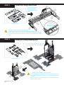
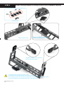
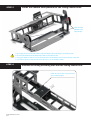
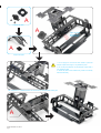
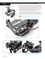
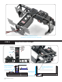
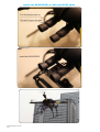
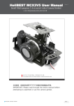
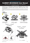
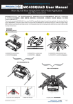
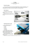
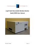
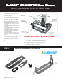
Version 1.0
HeliBEST MC6500PR
O User Man
ual
MC6500PRO
Manual
Portable, Multifunctional 2 Axis FPV Camera Gimbal
To obtain the best performance of this
product, please read through the manual carefully and assemble the parts according to
the detailed instructions.
Additional tools you need to use are as
DCS2600Digi
Digital Servo
follows: 2.0mm allen driver, small slotted
screwdriver or small phillips screwdriver,
Dampers
small clamp; high quality instant adhesive.
DCS2600Digi
Digital Servo
Dampers
Note: Most parts of this camera mount need
to be adhered by instant adhesive, so please
pay attention to the following points when
you using it:
1. Proper instant adhesive (Neither too much
nor too little);
2. Protect yourself (Do not drill the adhesive
in your mouth or eyes);
3. Absorb the extra undried adhesive by absorbent paper to keep the clean and appearance of camera mount
4. Apply the adhesive on the back of the
Camera Mount
Dampers
parts, which could keep the appearance of
the mount
The parts can be adhered quickly when using the high quality instant adhesive. And
the structural strength could meet the requirements in use. Please rest assured that
use.
HeliBEST MC6500PRO 2 Axis Camera Gimbal
Create the best aerial images show only
- Compatible with DJI WKM,FC1212-S/P,FY20A/30A,MK 2.0,etc.
- For X650V4/V8, X450/X450PRO, SIGMA Y6 and other models
- Lifting and Flip
- Mention two connections (hard-wired and soft connection)
- The use of special ultra-precision servo + 4 special rolling damper, the operation of
unparalleled smoothness and sophistication.
STEP 1
HeliBEST MC6500PRO User Manual
Page 1
Install the fixed platform for camera
STEP 2
Install the rolling control arms
Install the parts as seen
on the right, using the instant adhesive at crossed
position
Apply the adhesive
on the back of the
joints could keep the
appearance.
Prepare the parts
1. Pay attention to the installation direction of the parts;
2. Apply the adhesive on the back of the joints could keep the appearance;
3. Do not apply the adhesive on the fingers, to avoid leaving the finger prints on the parts
4. Do not loose your hand until the adhesive dry, to make sure that all the parts are adhered
perfectly
STEP 3
Install the rolling actuating arm
Install the parts as seen on the right, using
the instant adhesive at crossed position
Prepare the parts
As
s
em
ble
d
1. Pay attention to the installation direction of the parts;
2. Apply the adhesive on the back of the joints could keep the appearance;
3. Do not apply the adhesive on the fingers, to avoid leaving the finger prints
on the parts
4. Do not loose your hand until the adhesive dry, to make sure that all the
parts are adhered perfectly
HeliBEST MC6500PRO User Manual
Page 2
STEP 4
Install steering damper on rolling control arm (3 dampers needed)
Prepare the parts
Install the damper as seen
Using M2X4 screws to screw the damper
(Too tight may break the parts)
Using M2X4 screws to screw the damper
(Too tight may break the parts)
1. Using moderate force, too tight may break the parts;
2. Pay attention to the installation direction of the damper as seen above;
3. Do not apply too much force when rotate or press the damper output shaft rough, it may break the parts
4. Do not drip the adhesive into the damper output shaft, it may break the parts
HeliBEST MC6500PRO User Manual
Page 3
STEP 5
Install the camera fixed platform to the rolling control arms
Adjust the angle
Moderate Force
Using little glue
1. Do not apply too much force when rotate or press the damper output shaft rough, it may break the parts
2. Do not drip the adhesive into the damper output shaft, it may break the parts
3. Using proper adhesive if there is any loose at damper joints, but the adhesive could not dip into damper output shaft
4. If you find it is difficult to install the parts due to the hole on, you can enlarge it suitably
STEP 6
Connect the rolling actuating arm with the rolling control arm
Install the parts as seen, using the instant
glue at crossed position
HeliBEST MC6500PRO User Manual
Page 4
A
Prepare the parts
A
Adjust the angle
Moderate Force
Using little glue
A
Prepare the parts
1. Do not apply too much force when rotate or press the
damper output shaft rough, it may break the parts
2. Do not drip the adhesive into the damper output shaft, it
may break the parts
3. Check the parts to see whether they could run smoothly
after the assembly
The component "A" installed position as shown above, and fixed with instant glue
A
HeliBEST MC6500PRO User Manual
Page 5
STEP 7
Install the DSC2600Digi digital servo for camera gimbal
MC6500PRO comes with 2 ultra-precision digital servos DCS2600Digi,
which is for camera mount use only. The control program applied in
this servo is optimized for the use of the camera mount, so the servo
runs smoothly when working and reflects accurately. The moment of
force of DSC2600Digi is 3.0kg/cm; the speed could reach 0.06s/60. In
the meantime, it uses quick reaction coreless motor.
This performance of this specialized camera mount digital servo is
superior to other common tail servo in the market. The special design
meets the requirements for the performance of the camera mount.
1. Before installation, please take the servo horns off (as seen on the left)
2. Fix the servo by 2 nylon screw
3. Power on and confirm the angle, then install the servo horn of the servos
Using 2 nylon screws to fix the servo
Install the servo as the picture above
this is the installation method of pitch control servo
Screw with nylon screws in the back
HeliBEST MC6500PRO User Manual
Page 6
Pay attention to the trend of the servo wire (the trend
of the servo wire in above picture is recommended)
This is the installation of roll servo
(Pay attention to the direction of the servo output shaft)
STEP 8
Install the control linkages
approx 23mm
Connect to the 2nd. hole
12345678901
12345678901
When the rolling arm in a hori12345678901
12345678901
12345678901
zontal level, this should reach
12345678901
12345678901
approx 23mm
12345678901
12345678901
the angle of 90 degree
12345678901
12345678901
12345678901
12345678901
12345678901
12345678901
Connect to the 3rd. hole
12345678901
12345678901
12345678901
12345678901
123456789012
12345678901
123456789012
12345678901
123456789012
12345678901
12345678901234567890123456789012123456789012345678901234567890
123456789012
12345678901
12345678901234567890123456789012123456789012345678901234567890
12345678901
12345678901234567890123456789012123456789012345678901234567890
12345678901
12345678901234567890123456789012123456789012345678901234567890
12345678901
12345678901234567890123456789012123456789012345678901234567890
12345678901
12345678901234567890123456789012123456789012345678901234567890
12345678901
12345678901234567890123456789012123456789012345678901234567890
12345678901234567890123456789012123456789012345678901234567890
12345678901234567890123456789012123456789012345678901234567890
12345678901234567890123456789012123456789012345678901234567890
HeliBEST MC6500PRO User Manual
Page 7
1234
1234
1234
1234
1234
1234
1234
1234
The length of the linkage can be
1234
1234
1234
1234
1234
1234
adjusted according to your own
1234
1234
1234
1234
1234
1234
1234
1234
needs
1234
1234
1234
1234
1234
1234
1234
1234
1234
1234
1234
1234
1234
1234
1234
1234
this should reach the 1234
1234
1234
1234
1234
1234
angle of 90 degree
1234567890123456789012345678901212345678901234567890123456789
1234
1234
1234567890123456789012345678901212345678901234567890123456789
1234567890123456789012345678901212345678901234567890123456789
1234567890123456789012345678901212345678901234567890123456789
123456789012345678
1234567890123456789012345678901212345678901234567890123456789
123456789012345678
1234567890123456789012345678901212345678901234567890123456789
123456789012345678
123456789012345678
123456789012345678
123456789012345678
Connect to the 4 hole
Install the MC6500PRO on XAircraft X650 Value
Put the damper pipe on
Put the O-ring on the pipe
Install the MC6500PRO
HeliBEST MC6500PRO User Manual
Page 8