1
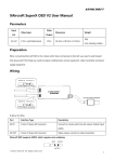
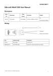
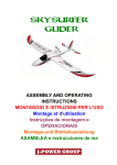
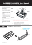
XAircraft FC1212-P User Manual V1.02 This Manual is for: FC1212-P and XAircraft Center 1.8 Contents DISCLAIMER OF LIABILITY ......................................................................................................................................... 1 Security Notes........................................................................................................................................................ 1 XAircraft FC1212-P Overview ................................................................................................................................... 1 FC1212-P Interface............................................................................................................................................... 2 FC1212-P LED Indication ................................................................................................................................... 2 FC1212-P Related Modules ............................................................................................................................... 3 Wiring of FC1212-P ...................................................................................................................................................... 3 Connect to Receiver ............................................................................................................................................. 3 Safety Notice.................................................................................................................................................. 3 HITEC,FUTABA,WFLY Receiver Wiring ............................................................................................. 4 JR,Spektrum Receiver Wiring ................................................................................................................ 4 AHRS Installation .................................................................................................................................................. 4 Install AHRS-S V2 and Compass ............................................................................................................. 5 Install AHRS-P................................................................................................................................................ 6 Install Autopilot ..................................................................................................................................................... 7 GPS LED Indication ...................................................................................................................................... 7 XAircraft Center Overview ......................................................................................................................................... 8 Installation............................................................................................................................................................... 8 Connecting FC1212-P with XAircraft Center............................................................................................... 8 FAQ of Connection....................................................................................................................................... 9 XAircraft Center Interface ............................................................................................................................... 10 XAircraft Center User Manual ................................................................................................................................ 11 Profile ..................................................................................................................................................................... 11 XAircraft Profiles ........................................................................................................................................ 11 Custom Profiles .......................................................................................................................................... 11 Remote Control .................................................................................................................................................. 16 General Input and Calibration .............................................................................................................. 17 REV TEST: Check the Response of Transmitter Control ............................................................... 17 Motor Power On Type ............................................................................................................................. 18 How to Use AUX Functions.................................................................................................................... 18 X.BUS Input ................................................................................................................................................. 19 Gimbal Settings .................................................................................................................................................. 19 Gimbal Remote Control Input............................................................................................................... 19 Turn OFF/ON Gimbal Auto-compensation by Transmitter ......................................................... 19 Gimbal Settings .......................................................................................................................................... 20 Servo Output Period ................................................................................................................................ 21 Autopilot ............................................................................................................................................................... 21 GPS ATT Mode ........................................................................................................................................... 21 Height Hold ................................................................................................................................................. 22 Return to Home (RtH) .............................................................................................................................. 22 Compass ............................................................................................................................................................... 23 Compass Calibration ................................................................................................................................ 23 Carefree......................................................................................................................................................... 23 Heading Lock .............................................................................................................................................. 24 Pilot Lamp ............................................................................................................................................................ 24 Design Rules ............................................................................................................................................... 24 Symbol .......................................................................................................................................................... 24 Indication ..................................................................................................................................................... 25 Show Lamp! Function .............................................................................................................................. 25 Firmware Upgrade............................................................................................................................................. 25 Firmware Upgrade FAQ ........................................................................................................................... 28 Quick Setup Guide..................................................................................................................................................... 29 Step 1: Choose Correct Profile ...................................................................................................................... 30 Step 2: Check the Transmitter function...................................................................................................... 30 Step 3: Calibrate the Compass ...................................................................................................................... 30 Step 4: Ground Test before Flight ................................................................................................................ 30 1. Test without Propellers ............................................................................................................... 30 2. Sticks Control Test ........................................................................................................................ 30 3. Auto-leveling Test ......................................................................................................................... 31 FAQ of Flight ................................................................................................................................................................ 31 No reaction to the throttle control, motors do not start. ................................................................... 31 Flap over when taking off ............................................................................................................................... 31 Keep turning to one side during flight ...................................................................................................... 32 Copter Heading is not stable ........................................................................................................................ 32 How to Use UBEC .............................................................................................................................................. 32 3 / 36 DISCLAIMER OF LIABILITY 1. Using XAircraft products within the limits permitted by local laws and PLEASE PAY ATTENTION TO THE AGING AND WORN PARTS, AND FLY WHEN THEY ALL regulations. XAircraft is not responsible for any illegal activities。 2. The FC1212-P and related modules are aeromodelling products only. Please strictly follow the aeromodelling safe function rules, XAircraft does not hold responsible for any control over its operation or usage. 3. Model aircraft are not toys! Fly under professional guidance and strictly follow instruction rules in this document. XAircraft is not responsible for consequences caused by improper install, wrong setting or operation. Security Notes 1. Familiarize yourself with fly environment and any obstacles. Identify any potential hazards such as power lines, cars, people, etc. 2. Do not fly the aircraft when fatigued, drunk or your mental state has been compromised which may cause an accident. 3. Stay away from wet areas. Do not fly in the rain or wet environments which can cause device failure and probably lead to danger. Do not fly at night or in windy conditions. 4. Stay away from any fire resulting in damage of the electronic parts or others such as the flight battery. 5. Do not fly alone during your preliminary flights. If you need help, please enlist the aid of an experienced pilot before flying for the first time. 6. Prepare rescue tools such as cell phones or other communication devices which should you need to call for help. 7. Please fly under the safe take-off weight, do not overload the aircraft otherwise will lead to danger. 8. Ensure all the equipment operates correctly before flight and that there is no transmitter interference or conflicts. 9. Do not touch any moving or powered parts. Do not try to catch the quadcopter which has rotating motors or blades for example. Keep loose clothing away from moving parts as they may get caught and could cause physical harm. 10. Always throttle down to minimum before fly. 11. Remove the propellers when testing the remote device or motors operation. Attach the propellers after you have tested that everything is working good to prevent an accident. 12. Assemble the aircraft with accessories XAircraft provides. XAircraft is not responsible for any consequence resulted from assembly with other accessories or modifications. XAircraft FC1212-P Overview XAircraft is FC1212-P is specialize design for multi-copter, support 2 to 8 frame multi-copter. 1 / 36 FC1212-P Interface Note: 1. AUX Function: XAircraft Center software set up for AUX1-3. 2. Output 1-Output 8 Default output is UltraPWM output , adequate for XAircraft UltraPWM high speed ESC , using other ESC need to create custom profile. 3. INPUT5 Flight mode (please connect XAircraft software to make sure the RC reflect correct). Mode Functions MEMO. INPUT5 disconnected Attitude Mode Normal Mode (NOR.) No Auto-leveling ability Attitude Mode (ATT.) Has the ability of auto-leveling. No-recommend to beginner Height Hold is available if autopilot is plugged-in and function is enabled. GPS Attitude Mode The copter will try to hold its position by GPS Warning: must ensure the GPS has (GPS ATT.) when you release the pitch and roll sticks. got enough satellites before flight, Height Hold is available. see the autopilot manual. FC1212-P LED Indication Light Flash Mode Indication Link Irregular Flash FC1212-P is communicating with XAircraft Center software ware. Port A~ Port B OFF Unconnected with software ware or no communication with PC. OFF No module connected. Solid ON Module connected and works normal. Flashing once in a while When there’s any communication data error with the module. If it keeps flashing should stop flying and check. System Four times flashing at FC system self-check. power on Fast Flashing in Green Throttle protection after system self-check. Put down the throttle, the protection will be canceled. 2 / 36 Double flashing in green No valid RC signal detected. Slow Flashing in green FC works normal, ready to fly. Green Light is Solid ON The copter is in flight Red light Solid ON Upgrading firmware. Or system Error: please contact with distributor or XAircraft directly. FC1212-P Related Modules Module Function MEMO. AHRS Must choose AHRS-S V2 or AHRS-P Attitude and Heading Referencing System Compass Autopilot Option. Offers better precision of heading. AHRS-P has a built-in Also provides heading lock and carefree functions. compass already Option. Provides Height Hold, Position Hold (GPS ATT mode) and Have to work with compass Return to Home functions. Pilot Lamp Option, show flight mode and warning. Wiring of FC1212-P Connect to Receiver Safety Notice After connecting the Receiver (RX) and FC1212-P, must check the Reverse Settings work well. You have to check the reverse settings of your transmitter: 1. Do the Ground Test without propellers installed after all assembly work done. 2. Or you can connect to XAircraft Center to do the Rev Test. WARNING: INCORRECT REVERSE SETTINGS MAY LEAD TO DANGER. 3 / 36 HITEC,FUTABA,WFLY Receiver Wiring JR,Spektrum Receiver Wiring Other functions: Go to the FC1212-P interface definition for connecting your RX with FC1212-P. AHRS Installation FC1212 - P is compatible with two AHRS modules: AHRS-S v2 and AHRS-P, option one what needed. 4 / 36 Install AHRS-S V2 and Compass Note: 1. Pay attention the direction of AHRS and Compass when install. 2. Have to use the shock absorption provided by XAircraft when install AHRS-S V2. 3. AHRS-S V2 can connect with any port of port A ~port E of FC1212-P. 4. Due to the compass is susceptible interference by electromagnetism, should avoid electric cables near the compass when install. AHRS-S V2 LED Indication Light Flash Mode Indication Red Flashing 4 times at power System self-check. on Green Flash randomly Red light is up when gyro over loaded. Solid ON AHRS calibrating or upgrading. Fast flashing at power on Gyro auto-calibration, no touch while the green light flashing avoid any vibration. Solid ON Connection with FC1212-P normally. Flashing once in a while Communication error with FC1212-P, if green light keep flashing have to stop flying and check cable Green light and red light in Communicating fatal error with FC1212-P, have to stop flying and check. turns Compass LED Indication Light Flash Mode Indication Green Solid ON Works normal. Blinking Calibrating, see Compass Calibration below. 5 / 36 Install AHRS-P AHRS-P has a built-in Compass, compass is susceptible interference by electromagnetism, should avoid electric cables near the AHRS-P. 6 / 36 Install Autopilot Autopilot can connect with any port of Port A ~ Port E on FC1212-P through 6 pin cable. Notice: 1. Have to work with Compass. 2. GPS should install higher than other electric devices, far away from UBEC ,RC, Video Transmitter or other devices to avoid interference on GPS signal. 3. Don't use GPS between buildings. GPS LED Indication Light Flash Mode Indication Red Fast Flash Flight mode is Normal mode Flash in one second Flight mode is Attitude mode Flash in five seconds Flight mode is GPS Attitude mode Fast Flash No satellite or less than 4 satellites connected. Flash in one second Low Accuracy GPS Attitude mode, 4-6 satellites connected. Green 7 / 36 Flash in five seconds High Accuracy GPS Attitude mode, 7 or more Satellites connected. XAircraft Center Overview Installation Get related software from XAircraft CD or XAircraft website (http://wiki.XAircraft.com). After enter the XAircraft WIKI site, click "Downloads" on left side. In the XAircraft Center Download page, you can download the latest and old XAircraft Center software and .NET Framework and USB driver. 1. Install NET Framework: if your PC never installed Microsoft .NET Framework 4.0 before, please download and install it. 2. Install XAircraft Center. Connecting FC1212-P with XAircraft Center 8 / 36 The Connect button is green when USB Link is connected with PC correctly. FAQ of Connection 1. Error information : connection timeout a) Ensure 4 pin cable connected correct with link port of FC1212-P, not other link port of AHRS or other modules. b) 2. Ensure 4 pin cable is well. Error information : Firmware version too low or Failed to get the configure data a) Update XAircraft Center to latest version b) Use the upgrade on line function of XAircraft Center to upgrade FC1212-P firmware. Also upgrade the other modules. 3. Connect button is always in gray. a) Ensure USB Link connection correct with PC. b) If USB Link connected well, can try to reinstall the USB Driver downloaded from XAircraft WIKI site. 9 / 36 XAircraft Center Interface 1. XAircraft Center version and Firmware version. 2. Language option, Chinese and English available. 3. Disconnect FC1212-P from XAircraft Center. 4. Profile: Including XAircraft and User group of profiles, different frame use different profile. 5. Remote Control: Configure and check the functions of transmitter. 6. Flight Control: Tune the gains for Flight Control. 7. Gimbal: Configure Gimbal auto-compensation and the shutter. 8. AHRS: Calibrate the AHRS and Compass, Check the health of sensors. 9. Autopilot: View the autopilot data including GPS and barometer. 10 / 36 XAircraft Center User Manual Profile XAircraft Profiles XAircraft official profile list is provided for XAircraft Frames. 1. Using XAircraft frames please follow the frame instruction; ensure direction of propellers and motors are correct. 2. If no special notice, the motor is using XAircraft UltraPWM ESC by default. 3. When XAircraft release new firmware and software, need to update XAircraft profile list online. 4. XAircraft profiles are read-only. Custom Profiles When you can’t find similar frame in XAircraft profiles or want to use normal ESC, you have to create your own profile in User profile list. 11 / 36 In the Profile Editor, you can input the basic information for your profile. Don’t forget to save your profile after settings changed. Using Normal ESC STEP 1: Create or Edit your own profile. STEP 2: Use flight style wizard to set up Mixer Table for your frame. Choose Normal ESC and select proper frame style: After choose the frame style, check the motors and propellers direction according the diagram on the right side. STEP 3: Save and Apply the profile. Common Frame Styles Here is the list of several style of frame styles. Direction of propellers must consistent with diagram, the ESC should connect with corresponding output port (M1~M8) of FC1212-P. 12 / 36 Quadcopter(X and + Style) Hexacopter(X, + and Y6) Octacopter (X, + and X8) 13 / 36 Use Other Frames If your frame is not in the wizard, you have to configure the Mixer Table according to the Mixer Rules. Type You can configure the outputs as UltraPWM ESC、 Normal ESC or Servo and set the Min, Home and Max value for them. The Min, Home Max value is preset by software ware when you change the Type. NOTICE: Don’t use UltraPWM ESC and Normal ESC together. 14 / 36 Mixer Rules There're only 4 rules to make a mixer settings. 1. Throttle: All the motors should be 100%, servos should be 0. 2. Pitch: Motors in +Pitch area are +100%, motors in –Pitch area motor are -100%. Servos should be 0. 3. Roll: Motors in +Roll area are +100%, motors in –Roll area are -100%. Servos should be 0. 4. All clockwise propellers are in -Yaw ‘area’, all counter clockwise propellers are in +Yaw ‘area’. Sample: Hexa Y6 1. All throttles are 100. 2. +Pitch area: M1, M2, M3 and M4 should be 100. -Pitch area: M5 and M6 should be -100. 3. +Roll area: M1 and M2 should be 100. –Roll area: M3 and M4 should be -100. M5 and M6 is not in +Roll and – Roll area, they should be 0. 4. +Yaw: M1, M3 and M5 should be 100. –Yaw M2, M4 and M6 should be -100. 15 / 36 So we got this Mixer Table (using Normal ESCs): Remote Control 16 / 36 General Input and Calibration 1. Flight Mode (Input 5): flip the Flight Mode switch on transmitter, check the mode shown on software and remember the position of the switch. 2. Calibration :if signal of throttle does not vary in full range when moving the throttle stick, or roll /pitch/yaw signal is not right at the red neutral line(e.g.: ), need to do the RC Calibration, click Calibrate button and follow the steps to calibration RC. REV TEST: Check the Response of Transmitter Control Click the REV Test button on the bottom, viewing the simulator diagram in the prompt window to check with your RC operation is consistent. if throttle , pitch , roll and yaw are not consistent with your stick operation, then select Rev option. Click Save button to save your settings. 17 / 36 Motor Power On Type 1. Normal: Throttle up to a certain level, the motors start. Throttle down to minimum after 0.5 second, the motors stop. 2. Arming: Throttle at minimum level, yaw to right to start the motors, yaw to left to stop the motors. How to Use AUX Functions You can configure the optional functions for your modules by assigning 3 position or 2 position switch. The switch channel can be connected to any port of Input6, Input7 or Input8. The picture shows a switch is connected with INPUT6. You can see the green signal switchover in Low, Mid and High when you flipping the switch on transmitter. For example the Return to Home function, choose High to enable the function. After setting saved, you will see the state changing as below: 1. Return to Home is OFF. 2. Return to Home is ON. AUX Tips For saving the RX channels, you can configure one switch for different function. For example, a 3-position switch can be configured as: Low for Carefree, Mid for nothing, High for Return to Home. 18 / 36 X.BUS Input Not Released yet. Gimbal Settings Gimbal Remote Control Input Input 9 and Input 10 of FC1212-P are for gimbal, respectively controlling pitch angel and shuttle action. After connected, signals shown in the Gimbal Input. Turn OFF/ON Gimbal Auto-compensation by Transmitter Gimbal auto-compensation is enabled by default. You can configure a switch on transmitter to turn ON/OFF the auto-compensation in AUX function. The picture shows a switch channel connected to Input7, and shows the state of auto-compensation disabled. 19 / 36 Gimbal Settings Note: FC1212-P does not support multi-circle servos. Multi-circle servo has no end-points. Auto-compensation Settings Angle Gain: For the roll and pitch of Gimbal, adjusting the gain can tune how much the servo compensates for different servo. Stick Speed Gain: Configure how fast the gimbal reacts to the pitch control from transmitter. Max and Min: Configure the servo end-points. Home: The original position of the servo. Configure Shutter Configure half-press (focus), press (shot) actions for the shutter. 20 / 36 In Remote Control, when Input10 signal arrives or exceeds the red neutral line, the shutter servo starts a sequence of half press (focusing) and press (shot) actions. The shutter triggered (Input10): Note: if the switch keeps stay at the position of triggering shutter, the shutter will keep doing the focus-shot again and again. The shutter untriggered (Input10): Servo Output Period Click the Output Period button to set the period for different servo. Period of digital servo can setting lower , for example 3ms, but the analog servo need to set to 10ms or more. Autopilot After install autopilot module, can use GPS Attitude mode, Height Hold and Return to Home functions. GPS ATT Mode Warning: Using GPS attitude mode, please ensure GPS has got enough satellites before the engines start. General Input in Remote Control shows the flight mode. In GPS ATT mode, the copter will try to hold its position after release the sticks of pitch and roll in 2 seconds. The picture below shows FC1212-P is under GPS ATT Mode. 21 / 36 IMPORTANT: There might be a brake before Position Hold entered in GPS ATT Mode; the brake depends on moving speed of copter. if speed > 0.2m/s then there's a brake. The brake stops if the brake-time more than 2 second. The brake stops when speed is lower than 0.2m/s. if speed < 0.2m/s then FC enter position hold directly. In Flight Control interface, you can tune the GPS gain of position hold, or disable the position hold. Height Hold Height Hold function is enabled by default. Autopilot use an integrated barometer for Height Hold, the precision of barometer is ±15CM in no wind condition. For improve suitability, we suggest tune height gain down to 20. Return to Home (RtH) Warning: Using Return to Home function, please ensure GPS has got enough satellites before the engines start. Configure the RtH function in AUX Input, can choose Input6, Input7 or Input8 for it. Do remember the position of the RtH switch on your Transmitter. You can configure the RtH Speed Gain to tune the speed of RtH. The default speed is fast, you can try 30 first. 22 / 36 Compass Compass Calibration Step 1: Select "Calibrate Compass in the next power on" in AHRS interface of XAircraft Center. Then disconnect with XAircraft Center. Step 2: Calibrate Compass outdoor in open air. Note: Since there’s no light on AHRS-P, users have to watch the red light on GPS. Suggest change the flight mode to GPS ATT mode to divide the flash mode of red light. Important: ensure the environment of calibration compass , building concrete ,high voltage wire, steeliness stuff will effect compass calibration。 Power on the copter, calibrate the compass following the compass light: 1. First fast flashing: prepare for the Horizontal Calibration 2. Slow flashing: do the Horizontal Calibration, rotate the copter 2 circle at least. 3. Second fast flashing: prepare for the Vertical Calibration 4. Slow flashing: do the Vertical Calibration, rotate the copter 2 circle at least. After vertical calibration, the compass light is solid on. For GPS red light, the light will indicate the flight mode after vertical calibration. Carefree In this mode, the front of copter is no more front. The front is defined base on the ground when motors start. Turn On Carefree: In Remote Control, you can configure AUX function to assign proper transmitter switch for carefree. Notice: the direction of front and back is means flight direction is the front not depend on user. Carefree Demo: 1. Before takeoff, copter heading (orientation) towards the east. 23 / 36 2. After takeoff, push pitch stick forward, copter fly to east, push roll to right, copter fly to south. 3. Then use yaw stick to make copter revolve 90 degree, head copter to north. 4. Push pitch forward, copter still fly to east; push roll to right, copter still fly to south. Heading Lock Heading Lock function is useful for beginners. When function is on, yaw stick is not controlling the yaw speed but yaw to a certain angle according yaw stick position, after yaw stick released, the heading of copter will turn back to the original when motors start. Turn On the heading lock: Set up a switch for Heading Lock in AUX function. You can use Input6, Input7 or Input8. Heading lock function demo: 1. Before takeoff, turn off heading lock, head to east. 2. After takeoff, turn off heading lock, keep yaw stick to left, copter rotates to left without stop; released yaw stick, copter stops rotation. 3. Turn on heading lock, heading turn to east automatic. Keep yaw stick to left, copter yaw to corresponding angle to left and stops at the position. Released yaw stick, copter heading is back to east. Pilot Lamp XAircraft Pilot Lamp is an optional device for FC1212-P. Pilot Lamp is used for indicating the status of copter, showing flight mode, function status and warning. You only need to plug the Pilot Lamp to output12 on FC1212-S to start to use it. And it requires v1.33 or higher FC firmware. Design Rules There's several rules when designing the indications that will make users understand the beeps and light flashes more easily. The faster the buzzer beeps, the more emergent is. The faster the flight flashes, user should pay more attention for that situation. The RED light only light up when serious problem occurred. Symbol Symbol Buzzer Indication Light Indication . short beep short flash - long beep long flash 24 / 36 x interval (the interval between two indications) interval () repeat repeat ~ yowl (beeping always) Solid ON For example(buzzer): (.x) means the buzzer will short beep again and again, (-.x) means the buzzer will has a long beep then a short beep, and repeats long beep short beep. Indication Buzzer Green Light Blue Light Red Light Indication Function Changed. When you switch the function status (change Flight Mode, turn on/off carefree, turn on/off heading hold, etc.), . then buzzer will beep once to tell you the FC has reacts your operation. RC Signal lost, that means the receiver is disconnected with the (..x) radio. But not support all the receivers. (..x) Flight Mode is NORMAL. (..x) Flight Mode is ATTITUDE, and Autopilot is not plugged-in. (-x) Autopilot is plugged-in, but GPS is not available. ~ (……) GPS is ready. Position Hold and Return to Home are available. (……) AHRS is disconnected. This is a special signal that can be turn on by your radio. When (……) (……) (……) (……) 'Show Lamp!' is on, the buzzer and lights will shows this signal. It can help you to find the copter when you lost it in the grass. Show Lamp! Function Turn on the show lamp function, buzzer sound faster in pilot lamp, all the lights keep flashing. Show lamp! function is for check the pilot lamp work normal or damaged。 Turn ON show lamp! function: Configure a switch for Show Lamp! function. You can use Input6, Input7 or Input8 for it. The picture shows using Input6 for the function. Firmware Upgrade Upgradable Modules: FC1212-P, AHRS-S V2, AHRS-P and Autopilot. Step 1: Before upgrade, confirm the Connect button is green and FC1212-P is connected. Click the right bottom 25 / 36 Firmware Upgrade to start. Step 2: In the prompted firmware list, choose the correct firmware. For example, if you want to upgrade AHRS-S V2, then click the upgrade button in the second row (high-lighted). You also can choose Offline Upgrade to browse the firmware file. Step 3: Disconnect 4pin cable from FC1212-P, and then click the start upgrade button. 26 / 36 Step 4: Plug the 4pin cable to AHRS-S V2 as screen shows. If you are upgrading Autopilot, the screen will show an Autopilot in the diagram. Step 5: Upgrading. 27 / 36 Step 6: Done. Firmware Upgrade FAQ 1. Incorrect Firmware: Check step 2 and step 4, you have to choose proper firmware and plug the 4pin cable to link port of proper module. 28 / 36 2. Stop at step 4 until it counting down to ZERO. Reason: probably your USB port can’t provide enough power for all devices which get the power from the upgrading device. Solution: 1. If you use a PC, use the USB port on the back of the case. 2. Disconnect all wiring form the module being upgraded. Quick Setup Guide Install FC1212-P and other modules on the frame well, suggest following the steps below to set up. And uninstall 29 / 36 the propellers before flight to ensure safety. Step 1: Choose Correct Profile Choose correct profile depend on your frame and ESC, the normal ESC need to set up custom profile except XAircraft UltraPWM ESC. Step 2: Check the Transmitter function In Remote Control: 1. Check the flight mode work normal in General Input. 2. Do the reverse test (Rev Test). 3. Do the Calibration. 4. Check AUX functions are configured correct, especially Return to Home, Carefree and Heading Lock. Step 3: Calibrate the Compass If you have a Compass installed, you have to calibrate it when first install or the installation position of electric changed. Step 4: Ground Test before Flight 1. Test without Propellers After electronic parts installation, DO NOT install the propellers and follow the steps. 1. Lowest the RC throttle then turn on the transmitter. 2. Power on copter. 3. Apply the throttle slowly. 4. Note if four motors rotate smoothly a) If motor does not rotate or not smoothly enough, please throttle down to the lowest then unplug copter. Check on electronic circuit and motors to retest until it works fine. b) If not in the right direction, lower the throttle down to minimum and power off copter. Swap any 2 motor wire of three connecting to ESC until it works in the right way. 5. Poke all control sticks to observe motor rotation speed changes or not. 6. Throttle back to lowest and power off copter. 2. Sticks Control Test After power-on test and everything goes fine then install propellers to do stick function test on ground. 1. Put copter level in ground, beside it is transmitter. 2. First throttle down to lowest then turn on the transmitter. 3. Power on copter. 4. Hold back the lift of copter (Be careful safety) and apply Throttle to 20% slowly and keep it for a while. 30 / 36 5. Observe whether all propellers spin freely to the right direction. a) If not in the right direction, lower the throttle to minimum and power off copter. Reinstall propellers to test again until it works in the right way. b) If not in a smooth way, throttle down to lowest and power off copter. Check electronic circuit and motors to retest until it goes well. 6. If every part works fine, and keeps the throttle at 20% and try to push stick slightly in Pitch, Roll and Yaw (stick value 30%).Feel whether aircraft attempts to move to the corresponding direction. 7. If showing wrong direction to any of Pitch, Roll and Yaw, adjust signal cable connection order of receiver to test again until it becomes normal. 8. Throttle back to lowest and power off copter. 3. Auto-leveling Test After X650 Value stick function test on ground now it goes sensor test. 1. Unplug Flight Mode channel signal cable (default Input 5). 2. Throttle down to lowest then turn on the transmitter. 3. Power on copter. 4. Squat and grasp the bottom side of copter to lift it higher than your head. 5. Apply throttle slowly to 20%. 6. Try to use the aircraft forwards, backwards, left side and right side and feel it whether aircraft has stopped your moving. 7. If no resistance, throttle down to lowest and power off copter. Check if electronic parts installs properly. (Like AHRS installation orientation or good connection).Then test again. 8. If aircraft reacts perfect, throttle down to lowest and power off copter. Now you can start your first fly and enjoy it. FAQ of Flight No reaction to the throttle control, motors do not start. Check the problems as below. 1. Motor warning that not received any valid signal: Normal ESC is used but configured as UltraPWM ESC. 2. System light of FC1212-P is flashing faster: throttle protection, use throttle subtrim to adjust the minimum throttle down a bit then try again. If problem is still not solved, connect to XAircraft Center to do the Rev Test and calibration. Flap over when taking off 1. Check if the propellers installation error or not. 2. Check if the direction of AHRS or Compass is correct. 31 / 36 Keep turning to one side during flight 1. Check the FC1212-P and Compass install direction. 2. Check the propeller install, to ensure the rotate direction is matched to the frame style, ensure all propellers installed in horizontal line. Propeller will to the side may because the motor installation is not straight for example the picture as below: Copter Heading is not stable Note: Copter heading keeps turning to left or right drift slowly is normal when there’s no compass plugged-in. If compass plugged-in: 1. Check around compass if there’s any electric (electromagnet, magnetizer) interference, make the wires tidy. If in the building may interference by steel reinforcement. 2. Redo the Compass calibration. How to Use UBEC When you mount more devices to FC, because the regulator on ESC can't supply enough power for all the devices, you need a third part 5V UBEC to supply power. For example, if you use a Camera Mount like CM130-TPS, the servos of the camera mount require an UBEC which can supply at least 3A current. 32 / 36 Step 1. Connect the UBEC to the 5th/9th of the power wire. The E3008 has 5 output connectors, and E3009 has 9. Step 2. Connect the UBEC to any input/output port hasn't been used on FC. I use Input12. If there's no port free, you can also connect the UBEC to your receiver. 33 / 36 Step 3. Use a pincer to pick out all the red wires of 3 pin cable from ESC. 34 / 36 Step 4. Isolate the copper end of the red wire. 35 / 36 Step 5. Connect the ESC to FC as usual. 36 / 36