1
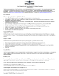
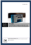
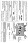
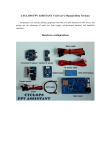
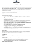
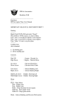
SY-link
An artificial horizon interface board
User’s manual 1.1
Product Description
The SY-link interface connects the FY-20A inertial flight stabilizer to the Eagle Tree OSD-PRO on screen
display expander. This provides an Artificial Horizon Indicator (AHI) using intertial measurements that
are independent from the weather, time of the day, temperature, and surrouning obstacles.
Pinout diagrams
SY-link pinouts is shown on the fig.1.
Each 2-pole plug has the first pin triangle
marking.
The onboard socket has 2 separate lines of
pins to connect Elevator and Aileron servo and
Rx plugs.
Interfacing with the FY-20A
The 6-wire ribbon cable should be
connected to the FY-20A device:
1-1 ground
1-2 +5V
2-1 AIL IN
2-2 ELE IN
3-1 AIL OUT
3-2 ELE OUT
Note: The plugs #2 and #3 should be
plugged in the upper (signal) row of the FY20A socket according to the labels on the FY20A top. The plug #1 should be plugged
vertically in the AIL IN socket.
If you are using the RUD IN, RUD OUT
and SWITCH IN pins, you can connect them
directly, as usual.
Please take a close attention to the polarity while making the connections.
Page 1
SY-link User`s Manual EN-US ©Syberian 2010
Interfacing with the Rx and servo
You should connect the Rx and servo plugs
to the SY-link as shown on the fig.3
(components side up)
If you have an autopilot, RTH or OSD
connected to the Rx Aileron and Elevator
channels, then daisy-chain those signals:
Rx->Autopilot(OSD)->SY-link
All the plugs has their power and ground
pins connected together. Also SY-link is
powering the FY-20A from the onboard servo
plugs.
Interfacing with the EagleTree™ Elogger V3™
SY-link is utilizing the Temp2 and Temp3
inputs of the Elogger V3 as shown on the fig.4.
Connect the plug #4 to the 2nd row of the
Elogger V3™ gauge socket so the 1st socket
goes to the middle pin of Temp2 and the 2nd
socket goes to the middle pin of the Temp3
group.
Elogger V3™
(label is on the backside)
To display an AHI with the EagleTree ™
airborne system you need the Elogger V3™ and
OSD Pro™ being connected and set up
according to their manual.
To setup and enable an AHI indication on
the EagleTree™ OSD Pro™ please do the
following steps:
Select the on-screen menu Configure
Artificial Horizon, launch the AHI Sensor
Calibrate Wizard and follow the on-screen
instructions. Then select Show Artificial
Horizon?: YES and exit the on-screen menu.
After all, you have to see an AHI line across
the crosshair which should move while tilt the
plane.
Page 2
SY-link User`s Manual EN-US ©Syberian 2010
AHI without stabilization
If your model either has differential ailerons or split elevator or is highly aerobatic, or there are any
other reasons you can’t use the FY-20A stabilization functions – anyway you can use the AHI indication.
Just connect the aileron and elevator Rx inputs in parallel to any channel of your receiver with Y-cable to
obtain any PPM pulses. Servo outputs of the SY-link are not connected.
Thus you will have an AHI indication without stabilization functions.
Working with elevons or V-tail
SY-link cannot work directly with mixed signals, such as elevons or V-tail.
If you are intended to use the SY-link on the flying wing, or V-tail glider, you have to disable the
internal mixing of your Tx and FY-20A and connect the external V-tail or elevons mixer between the SYlink and servos.
Known limitations
- SY-link is NOT the stabilizer, it is an interface board. Thus, if your FY-20A will sense the 45
degrees left roll in the steady flight, you’ll see the same on your OSD screen.
Page 3
SY-link User`s Manual EN-US ©Syberian 2010