1
user Manual
N O
L I M I T
REV. 6
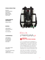
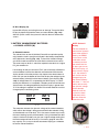
This is the operations manual for the
Hollis PRISM 2
This manual, specifications and features of the PRISM 2
are proprietary and copyright Hollis Inc., 2013.
This document cannot be copied or distributed without
the prior agreement and authorization from Hollis Inc.
All information contained is subject to change. Contact the
manufacturer for the latest information. www.hollisgear.com
The PRISM 2 is manufactured in the USA by Hollis Inc.,
2002 Davis Street, San Leandro, CA 94577. USA
Ph (510) 729-5100
EC Type approved by SGS UK Ltd. Weston-super-Mare.
BS22 6WA. Notified Body No. 0120.
Testing conducted by ANSTI Test Systems. Hants.
To ensure your user information is up to date. Please check
www.hollisgear.com for updates to this manual.
WARNINGS, CAUTIONS, AND NOTES
Pay attention to the following symbols when they appear throughout
this document. They denote important information and tips.
WARNINGS: are indicators of important information that if
ignored may lead to injury or death.
CAUTIONS:
indicate information that will help you avoid product
damage, faulty assembly, or unsafe conditions.
NOTES: indicate tips and advice.
i |
PRISM 2 DESIGN TEAM
Bob Hollis
Chauncey Chapman
Art Ferguson
Robert Landreth
Matthew Addison
Peter Readey
PRISM 2 MANUAL
WRITTEN BY
Matthew Addison
EDITORS
Jeffrey Bozanic
Chauncey Chapman
John Conway
Gerard Newman
CONTRIBUTORS
Jeffrey Bozanic
Gerard Newman
Dr. Richard Pyle
Sharon Readey
Kevin Watts
WARNING:
USE OF THE PRISM 2 MANUAL
This user manual does not, nor is it intended to contain any information needed to safely dive with any type
of SCUBA apparatus. It is designed as a guide for the
proper setup, operation, maintenance, and field service
of the Hollis PRISM 2 CCR only. It does NOT take the
place of a recognized training agency instructor-led
Hollis PRISM 2 eCCR
User Manual
Document Control Number:
12-4072 Rev. 6
Publish Date: 7/17/2013
diver-training course or its associated training manual(s)
and materials. This user manual is intended to be used
only as a type specific addition to such training and
materials, and as a user reference. This manual cannot
be used as a substitute guide for any other type of Self
Contained Underwater Breathing Apparatus (SCUBA).
| ii
GENERAL SAFETY
STATEMENTS + WARNINGS
WARNING: GENERAL SAFETY
No person should breathe from, or attempt to operate in any way, a Hollis PRISM 2
rebreather, or any component part thereof, without first completing an appropriate
Hollis Certified user-training course.
Further, no PRISM 2 diver should use a Hollis PRISM 2 without direct Hollis instructor supervision
until they have mastered the proper set-up and operation of the Hollis PRISM 2 rebreather. This
includes new PRISM 2 divers as well as PRISM 2 certified divers who have been away from diving for
an extended period of time and would benefit from an instructor-led refresher course to regain skills
mastery of the Hollis PRISM 2. Failure to do so can lead to serious injury or death.
The PRISM 2 rebreather can, as with any closed circuit breathing loop, circulate breathing gas that
may not contain a sufficient quantity of oxygen to support human life. The breathing gas within the
Hollis PRISM 2 loop must be closely monitored and manually maintained with a safe oxygen content
by you (a properly trained and alert user) at all times.
The PRISM 2 computer-controlled addition of oxygen to the breathing loop is intended as a failsafe back-up system to you, the primary controller. If you (either knowingly or by inattention) allow
the PRISM 2 computer to control oxygen addition to the breathing loop at any time, you are diving
outside the principals of your PRISM 2 training - assuming any and all possible risk.
WARNING: HIGH PRESSURE OXYGEN
The PRISM 2 uses cylinders, gas feed lines, pressure gauges and other devices which will contain
pure oxygen at high pressure when in operation. Oxygen by itself is non-flammable, however it supports combustion. It is highly oxidizing and will react vigorously with combustible materials. Oxygen
at elevated pressure will enhance a fire or explosion and generate a large amount of energy in a short
time.
The user must maintain all parts of the PRISM 2 that can come into contact with high-pressure
oxygen as oxygen-clean components. This includes scheduled servicing by a Hollis service professional, and using approved oxygen-compatible lubricants on any part of the gas delivery systems
that will come into contact with high-pressure oxygen.
If any part of the oxygen-clean system comes into contact with contaminants or is accidentally
flooded with any substance (including fresh water), you MUST have the entire high-pressure oxygen
system serviced by an authorized PRISM 2 service professional prior to use. Failure to do so can
cause fire or explosion and lead to serious injury or death.
iii |
WARNING: DESIGN AND TESTING
The Hollis PRISM 2 has been designed and tested, both in materials and function to operate safely
and consistently under a wide range of diving environments. You must not alter, add, remove, or
re-shape any functional item of the Hollis PRISM 2. Additionally, NEVER substitute any part of the
Hollis PRISM 2 with third-party items which have not been tested and approved by Hollis for use
with the PRISM 2.
This includes, but is not limited to, hoses, breathing assemblies, electronics, breathing gas delivery
assemblies and their constituent parts, sealing rings, valves and their constituent parts and sealing
surfaces, latches, buoyancy devices, inflation and deflation mechanisms and on-board alternate
breathing devices.
Altering, adding, removing, re-shaping or substituting any part of the Hollis PRISM 2 with nonapproved parts can adversely alter the breathing, gas delivery or CO2 absorption characteristics of
the Hollis PRISM 2 and may create a very unpredictable and dangerous breathing device, possibly
leading to serious injury or death.
Non-approved alterations to functional parts of the PRISM 2 will automatically void all factory warranties, and no repairs or service work will be performed by any Hollis service professional until the
altered PRISM 2 unit is brought back into factory specifications by a Hollis service professional at
the owner’s expense.
WARNING: COMPUTER / CONTROLLER-SPECIFIC WARNINGS
This computer is capable of calculating deco stop requirements. These calculations are predictions
of physiological decompression requirements. Dives requiring staged decompression are
substantially more risky than dives that stay well within no-stop limits.
Diving with rebreathers and/or diving mixed gases and/or performing staged decompression
dives and/or diving in overhead environments greatly increases
the risks associated with scuba diving.
WARNING: CAUSTIC MATERIAL
The CO2 absorbent used in the scrubber is caustic alkaline material. Take steps to protect yourself
from direct lung and skin contact. Furthermore, poor management of the breathing loop could
lead to water contact with the CO2 absorbent, causing a “caustic cocktail” (very caustic liquid).
This could lead to severe chemical burns and if inhaled - possible drowning. Proper handling
procedures, pre-dive checks, dive techniques, and maintenance mitigates this risk.
| iv
WARNING: COMPUTER SOFTWARE
Never risk your life on only one source of information. Use a second computer or tables.
If you choose to make riskier dives, obtain the proper training and work up to them slowly to
gain experience. Always have a plan on how to handle failures. Automatic systems are no
substitute for knowledge and training. No technology will keep you alive. Knowledge, skill,
and practiced procedures are your best defense.
WARNING: USER-PACKED RADIAL SCRUBBER
As of this writing, the Hollis PRISM 2 design does not include any technology or other device which
can detect or warn of potentially dangerous levels of carbon dioxide (CO2) within the breathing loop.
The Hollis PRISM 2 utilizes a user-packed, radial design CO2 scrubber. Only Hollis tested and
approved CO2 absorbents should be used, and factory-stated maximum scrubber durations
must NEVER be exceeded. Exceeding factory stated scrubber durations for a tested material will
eventually lead to serious injury or death.
It is entirely possible that, for any number of reasons including but not limited to: channeling,
ambient temperature, exhausted, damaged, inappropriately stored, or (for whatever reason), inert
scrubber material, the chemical and thermodynamic reaction required to sequester gaseous CO2
will not occur as expected, and a toxic, and possibly fatal level of gaseous CO2 within the breathing
loop can result.
You must carefully follow all instructor and manufacturer recommendations for use and handling
of CO2 absorbent, never use a CO2 absorbent if you cannot verify that it is able to sustain CO2
absorption and carefully pack the radial scrubber and complete a system pre-breathe prior to each
immersion, as you were taught in your training course.
Further, you must carefully monitor yourself for any symptoms of possible CO2 poisoning whenever
you are breathing from the Hollis PRISM 2, and bail-out to open circuit should any physical or mental
symptom lead you to suspect elevated CO2 levels in your breathing loop. Failure to bailout at the first
sign of trouble can lead to serious injury or death.
v |
WARNING: WEIGHTING OF THE HOLLIS PRISM 2
Unlike open circuit scuba gear, it is possible for the Hollis PRISM 2 breathing loop to flood, causing
the rebreather to quickly become 17 pounds negatively buoyant (not including any user-added
weight or offsetting buoyancy inflation). It is the responsibility of the diver to insure that the Hollis
PRISM 2 is never weighted in such a way that it is not possible for the installed buoyancy device
to overcome the flooded weight of the unit plus any diver-added non-detachable weights, and still
provide enough positive buoyancy at the surface to keep the divers head well above water.
Consult your instructor, dealer, or call the Hollis factory directly with any questions or concerns.
Failure to maintain positive buoyancy at the surface with the Hollis PRISM 2 in a fully flooded state
can lead to serious injury or death.
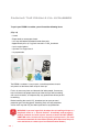
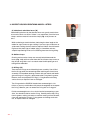
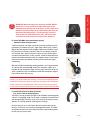
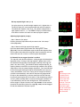
WARNING: PROPER BATTERIES
ONLY name-brand batteries (such as “Duracell” or “Eveready”) may be used to power the PRISM
2. Off-brand / Discount batteries have been found to vary greatly in quality of materials from batch
to batch (and even piece to piece!) Therefore they may not perform as expected, or be capable of
consistently delivering the power required to drive the components, despite battery voltage levels
reported by a battery voltage meter.
While off-brand / discount batteries are perfectly acceptable for use in toys and flashlights,
they have no place in life support gear and must never be used to power any component of
your PRISM 2.
Because of the potential rapid drop-off of charge from rechargeable batteries, rechargeable
batteries are not recommended for use with your PRISM 2 rebreather and must not be used.
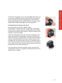
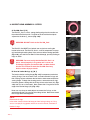
Diagram showing rapid discharge of non-branded batteries
that in life support gear can result in unnecessary hazards.
The full article, “Are Expensive Batteries Worth The Extra
Cost?” is available at Wired.com
Image courtesy of Rhett Allain, Wired
| vi
TABLE OF CONTENTS
General Safety Statements & Warnings
PART 1
SYSTEM OVERVIEW
SECTION 1
iii-vi
PART 3
SKILLS + DRILLS
SECTION 1
IN-WATER SKILLS
SECTION 2
ARTICLE: MINIMUM, MAXIMUM AND
OPTIMAL LOOP VOLUMES AND WORK OF
BREATHING
SCHEMATICS + DESIGN
SECTION 2
DESIGN PHILOSOPHY
ARTICLE: TAKING CARE OF YOUR
OXYGEN SENSORS
ARTICLE: THE SOLENOID AND
THE PID CONTROLLER
SECTION 3
FITTING YOUR PRISM 2
SKILLS + DRILLS COMPLETION LIST
PART 4
MAINTENANCE +
CLEANING
SECTION 1
SERVICE FACILITY & YOU
ARTICLE: STABILITY
SECTION 2
PART 2
PART 5
SETUP
SECTION 1
AN O-RING CLEANING PRIMER
SECTION 2
PACKING THE PRISM 2 CO2
SCRUBBER
SECTION 3
USING CHECKLISTS
SECTION 4
ROUTINE CLEANING
APPROVED PRODUCTS,
CAPACITIES, & SPECS
SECTION 1
THE LANGUAGE OF OXYGEN
SECTION 2
LIST OF APPROVED PRODUCTS
FOR USE IN YOUR PRISM 2
SECTION 3
COMPONENT CAPACITIES + SPECS
COMPONENT INSPECTION CHECKLIST
SECTION 4
SECTION 5
GLOSSARY
ASSEMBLY ORDER CHECKLIST
SECTION 6
PRISM 2 OPERATIONAL CHECKLIST
SECTION 7
POST DIVE CHECKLIST
SECTION 8
MAINTENANCE + REPAIR LOG
vii |
SECTION 5
NOTES
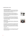
PART 1 . SECTION 1
System overview
design philosophy
The PRISM family of rebreathers has a long and illustrious history, and it is
considered one of the foundation platforms of the modern day electronically
controlled “sport” rebreather.
The PRISM 2, like its forerunner the PRISM Topaz, is a digitally controlled
electronic closed circuit rebreather with split front-mounted over the
shoulder counterlungs (OTS-CL). It incorporates a radial design scrubber for
the best possible duration and work-of-breathing. All gas delivery systems
on the PRISM 2 have both automatic and manual function.
MANUAL CONTROL OR COMPUTER CONTROL?
One of the ongoing debates when discussing rebreather safety is whether manually
controlled or electronically controlled rebreathers are safer. From the day in 1995
when PRISM Topaz class #1 was held in Hermosa Beach, CA, students were taught
to “fly” their rebreathers manually by watching their secondary analog displays and
manually injecting oxygen and diluent as needed.
From day one, PRISM students were taught that the primary control system was
always the divers brain. It wasn’t until the last dive of the last day of class that students were told, “OK, you can turn on your electronics and experience a computer
controlled dive”.
Diving with the computer monitoring the oxygen and the user keeping an eye on
everything with (at that time) a Heads Up Display primary and a wrist-mounted analog
secondary sure kept us busy, but we quickly realized that the computer was a LOT
better at closely maintaining a setpoint! We also realized that our instructor had
trained us to be manually controlled rebreather divers with the safety of “computer
over-watch”.
Why two independent monitoring systems in one rebreather? Simply put, electronics,
batteries and wiring combined with salt water (or even fresh water) do not get along
well together. While we can seal circuit boards and wiring interfaces against water
intrusion, rebreathers should have a diver accessible compartment to change batteries, and because of this need for accessibility, flooding can occur.
This is the Achilles heel of rebreathers with on-board electronics. Any time an O-ring
sealed Compartment is unsealed, the potential for debris to get on the O-ring and
cause the compartment to flood during the next dive is increased.
So, with two separate systems onboard with separate battery compartments, if one
battery compartment floods and destroys the battery, we simply switch to the other
monitoring system to safely end the dive. When our dive is over, we dispose of the
wiring harness and battery, clean the compartment and put in a fresh battery and
new O-ring(s).
| 2
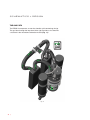
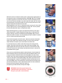
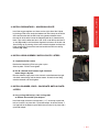
SCHEMATICS + DESIGN
THE GAS PATH
The PRISM 2 incorporates an over-the-shoulder split counterlung design.
The gas flows through the loop from left to right shoulder as has become
a standard in the recreational rebreather market (Fig. 1.1).
Fig. 1.1
3 |
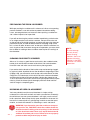
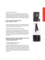
PART 1 . SECTION 2
OXYGEN & THE EXHALATION SIDE OF THE LOOP
Pure oxygen injection into the system, whether manually or electronically,
via the solenoid, is injected into the exhalation side of the breathing loop.
This design insures that a diver can never inadvertently get a high PO2 dose
of oxygen while diving, and that oxygen has plenty of time to properly mix
with the loop gas and thereby avoid potentially dangerous O2 spikes.
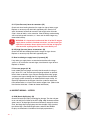
HEAD PLATE + RED CO2 SEAL
Once the diver-exhaled gas enters the head, it travels into the head plate,
which is also where O2 injected by the solenoid enters the breathing loop.
The red CO2 seal (Fig. 1.2) which seals the scrubber basket to the head
plate sits in a groove at the end of the head plate facing the scrubber
basket. The Red CO2 seal must be in place at all times during diving operations! Failure to insure that the Red CO2 seal is properly installed may
lead to injury or death.
WARNING: Breathing from the PRISM 2 without the Red CO2
Seal in place will result in 100% gas bypass of the scrubber.
Fig. 1.2
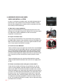
THE SCRUBBER BASKET
The gas leaves the head plate and enters the radial scrubber basket
through its center tube (Fig. 1.3). As the gas radiates outwards through
the CO2 absorbent and towards the bucket walls, exhaled CO2 is
chemically sequestered (adsorbed) by the CO2 absorbent, and any added
oxygen is mixed with the loop gas as it travels through the scrubber
granules. Upon exiting the scrubber, the heated gas enters the thermal air
jacket area between the basket and bucket.
Fig. 1.3
The air jacket serves two purposes: First and most important, it insulates
the scrubber material from colder external temperatures, which helps
increase the efficiency of the absorption process. Secondly, the moisture
in the heated gas exiting the scrubber has an opportunity to condense
along the cooler bucket wall, dropping the overall humidity of the gas
entering the oxygen sensor housing.
| 4
From the thermal jacket, the gas flows up through the scrubber basket
flow vanes (Fig. 1.4). This restriction creates higher gas velocities in the
sensor area without increasing work of breathing, further dropping the
dew point of the gas as it reaches the oxygen sensors. By using natural
condensation along the surface of the bucket wall and manipulating gas
velocities in the area around the O2 sensors, we are able to keep the
sensors as dry as possible without adding complexities such as sponges
or other moisture blocking devices.
Fig. 1.4
THE INHALATION COUNTERLUNG
The inhalation counterlung is a 3.5 L (optional 2.5 L) front-mounted split
counterlung design (Fig. 1.5) made of rugged nylon with a food-grade
urethane interior. It houses the automatic diluent addition valve (ADV),
counterlung drain, hose mounting hardware and BCD inflation hose wrap
at its front.
The hose attaching hardware for both the head and DSV/BOV assembly
attaching points (Fig. 1.6) are welded into place, so they cannot become
loose and cause an unintended loop flood. The DSV/BOV hose attaching
hardware is “keyed” (Fig. 1.7) and will only accept the corresponding
hose assembly elbow, thereby avoiding incorrect assembly of the loop
which would result in potential reversal of gas flow within the loop.
Behind each counterlung, under the Fastex Buckle panel are weight
pockets (Fig. 1.8) which will accept up to 5 lbs/2.3 kg of hard or soft
weight. The weight pouch flap is held in place with Velcro. There are 2
D-rings on the counterlung, one on the side and one at the bottom. Each
counterlung has a water drain at its bottom (Fig. 1.9) to drain fluids as
they accumulate during a dive. The Fastex clip panel on the back of the
counterlung contains 2 Fastex clips for clipping the counterlungs to the
harness, backplate, and one chest strap with Fastex clips.
Fig. 1.5
Fig. 1.6
Fig. 1.7
Fig. 1.8
Fig. 1.9
5 |
PART 1 . SECTION 2
ADV (AUTOMATIC/MANUAL DILUENT ADDITION VALVE)
Having the ADV (Fig. 1.10) on the inhalation side of the loop makes sense
for several reasons. Should the oxygen content ever become dangerously
low, dangerously high, or the diver begins feeling “abnormal”, a known
normoxic gas is immediately available while still breathing from the loop
prior to switching to bailout*. Therefore, having the diluent as close to the
mouthpiece as possible is the best way to insure that fresh breathing gas
of known and safe oxygen content is only a breath away.
*(Not applicable if the diluent is a hypoxic mix)
Fig. 1.10
The ADV is held in place by a threaded fitting welded to the counterlung.
To remove the valve for servicing, unscrew the outside retaining nut by
turning it counter-clockwise until the valve comes loose. There is a rubber
gasket under the valve which seals the valve body to the counterlung
fitting. The removable plunger activates a Schrader valve which allows the
gas to flow into the loop. The counterlung fitting is keyed so the valve will
not rotate while in use. While the valve is shipped from the factory with the
QD fitting facing up, the valve will work in any rotation.
THE EXHALATION SIDE COUNTERLUNG
The Exhalation side counterlung is of similar build and size to the
Inhalation side counterlung in all respects excepting it houses the manual
oxygen addition valve and the automatic, adjustable loop over-pressure
valve (OPV). (Fig. 1.11)
Fig. 1.11
BREATHING HOSES + HARDWARE
The Breathing hoses (Fig. 1.12) are 15” X 11/2” fixed-length rubber
breathing hoses. They can not be cut to a different length. The
Inhalation hose hardware which connects the hose to the DSV/BOV and
counterlungs, also houses the inhalation mushroom valve on the DSV
side of the hose. The BOV inhalation hose does not house the inhalation
mushroom valve. All mounting hardware is held in place by two Oetiker
clamps on each side of each hose.
Fig. 1.12
| 6
OPV (OVER PRESSURE VALVE)
The OPV (Fig. 1.13) is an automatic or manual adjustable pressure relief
valve which is screwed into a fitting welded onto the front of the exhalation
counterlung. To adjust the release pressure of the ADV, simply turn the
body of the valve clockwise to increase the cracking pressure and counterclockwise to decrease cracking pressure. To operate the valve manually,
simply depress the body of the valve. The OPV is not a serviceable part so
should it ever fail, it must be replaced.
Fig. 1.13
MANUAL OXYGEN ADDITION VALVE
The manual oxygen addition valve (Fig. 1.14) is located on the inside
of the exhalation counterlung. It is a push button valve operated by
a schrader valve. Under the quick disconnect fitting is a 0.0020 inch
flow restrictor, to meter the injection of oxygen into the Loop. The
manual oxygen valve is held in place by a threaded fitting welded to
the counterlung. To remove the valve for servicing, unscrew the outside
retaining nut by turning it counter-clockwise until the valve comes loose.
There is a rubber gasket under the valve which seals the valve body to the
counterlung fitting. The counterlung fitting is keyed so the valve will not
rotate while in use. While the valve is shipped from the factory with the QD
fitting facing up, the valve will work in any rotation.
Fig. 1.14
DSV (DIVE SURFACE VALVE)
The Dive Surface Valve (Fig. 1.15) is a neutrally buoyant one-way loop
“shut down” valve with a water purge. The rotating barrel is made of
stainless steel. The exhalation mushroom valve is seated on the right side
of the valve housing.
Fig. 1.15
BOV (BAIL-OUT VALVE)
BOV (Bail Out Valve) (Fig. 1.16) is a unique 2-position neutrally buoyant
loop shutdown valve with an in-line second stage for single action bail out
to open circuit. When the lever is in the top position, the valve in closed
circuit mode. The lower position is open circuit bail-out.
Fig. 1.16
7 |
PART 1 . SECTION 2
BATTERY COMPARTMENT COVER
The battery compartment cover (Fig. 1.17) is made of aluminum. The cap
utilizes two O-rings for redundant water tightness, a radial seal on the lip
of the cap and a compression seal on the top of the battery compartment
housing.
There is an automatic pressure relief valve built into the top of the cover to
vent excess pressure should the battery compartment flood. If the pressure
release valve were ever to actuate because of a battery compartment flood
or solenoid gas containment loss, the valve will open to vent the excess
pressure and close as soon as the pressure has been released.
Fig. 1.17
BATTERY COMPARTMENT
The battery compartment (Fig. 1.18) holds two sets of batteries: two 9V alkaline batteries wired in parallel which powers the solenoid, and one SAFT
3.6 volt LiON (Lithium Ion) battery which powers the Heads Up Display. The
sealed bulkhead power connector at the bottom of the compartment is a
female molex connector. A foam insert holds the batteries in place.
Fig. 1.18
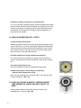
O2 SENSORS, SENSOR HOLDERS, CONNECTOR + PINS
The 3 O2 sensors are located in a chamber above the scrubber basket.
This insures a low condensation area and consequently drier O2 sensors.
The sensors are Hollis (PRISM 2 Ver.) which have an operating range of
8.5 mV-14 mV in air and 40.6 mV-67 mV at 100% O2 at 1 atm pressure. The
holders are removable to give users better access to the O2 sensors, wiring
harness and connector pins (Fig. 1.19). The holders are manufactured
from a soft silicone material to help protect the O2 sensors from vibration
and minor impact forces.
Fig. 1.19
See “Taking Care of your Oxygen Sensors” on the next page for more
information.
| 8
TAKING CARE OF YOUR OXYGEN SENSORS
The best way to care for an exotic animal is to first acquire some knowledge about it’s likes and
dislikes, and environments that will help the animal thrive. Likewise, having a working knowledge
of what is and is not good for the health of your oxygen sensors will help you take the best care
possible of them, and hopefully avoid unnecessary mid-season damage replacement. Here are
some important questions, and their answers.
WHAT IS A GALVANIC O2 SENSOR?
An oxygen sensor is a very small electrochemical generator. Some people equate them to a battery, but
that comparison is largely incorrect since a battery does not produce electricity as the O2 sensor does,
and the O2 sensor does not store electrical energy as a battery does. Understanding that the O2 sensor is
more like a delicate power-generating machine than a robust Duracell D battery is your first clue in understanding how they should be handled.
WHAT MATERIALS ARE USED TO MANUFACTURE
THE HOLLIS PRISM 2 SENSORS?
The body of the sensor is made of High-Density Polyethylene (HDPE). The membrane on the front of
the sensor is a thin Teflon gas permeable membrane. The internal components are comprised of a lead
anode, a precious metals-plated cathode, a base pH electrolyte consisting of mostly water and a bit of
Potassium Hydroxide. A printed circuit board (PCB) with resistor-thermistor temperature compensation
circuitry is heat sealed to the outside back of the sensor.
WHAT ENVIRONMENTAL CONDITIONS ARE BEST AND
WORST FOR THE O2 SENSOR?
Your “PSR” series O2 sensors are happiest between 32 oF/0 °C and 122 oF/50 °C. Operating or storing
the O2 sensor above 122 oF/50 °C will prematurely dry out the electrolytic fluid and destroy the sensor.
Operating or storing the O2 sensor below 32 oF/0 °C will freeze the electrolytic fluid causing expansion
damage to the internal components, Teflon membrane, and possibly leakage of the electrolyte upon
thawing, thereby destroying the sensor.
9 |
PART 1 . SECTION 2
HOW DOES A CHANGE IN AMBIENT TEMPERATURE INFLUENCE
THE O2 SENSOR’S PERFORMANCE?
Temperature influences the signal output at a rate of 2.54% per °C. Gradual ambient changes in temperature can be maintained within +-2% accuracy by processing the signal output through the resistor - thermistor temperature compensation network. Rapid changes of 59 oF/15 °C require 45-60 minutes for the compensated signal output to equilibrate, e.g. the electronic thermistor reacts immediately to offset the change
in the sensor, but the sensing membrane and electrolyte reacts at a much slower rate.
Because of the exothermic (heat generating) reaction of CO2 scrubbing taking place next to the sensor
housing during diving operations, it is important that you calibrate the sensors close to “room temperatures” (60 oF/16 °C – 80 oF/27 °C) so you are not temporarily outside of the 59 oF/15 °C “rapid compensation” range while diving.
HOW DOES PRESSURE INFLUENCE THE OXYGEN SENSOR’S PERFORMANCE?
Pressure influences the signal output on a proportional basis. The sensor is accurate at any constant pressure up to 30 ATM provided the sensor (front and rear membranes) is pressurized and decompressed
gradually (similar to human lungs). The membranes, especially the front sensing membrane, do not tolerate
rapid changes in back pressure or vacuum. Normal diving operations will not generate pressures beyond
which the sensor is designed to operate.
If you use a pressure vessel to check current limiting, it is important that you slowly bleed off the pressure
in the vessel after the checks are completed. The optimal analysis pressure range is 5-30 psig, up to 100
PSIG, with a flow rate of 1-2 scfh. The longer you keep the cells pressurized, the slower you need to bleed
off pressure. This procedure should sound familiar to divers.
WHAT IS THE MAXIMUM ALTITUDE THE OXYGEN SENSOR
CAN BE EXPOSED AND STILL FUNCTION?
The oxygen sensors have been tested up to 20,000 ft/6096 m with no error.
DOES MOISTURE OR WATER AFFECT THE OXYGEN MEASUREMENT?
If moisture or water is present in the gas stream it will not damage the oxygen sensor or analyzer, but it can
collect on the sensor’s sensing membrane, thus blocking the flow of gas.
| 10
WHAT HAPPENS WHEN THE O2 SENSOR HAS BEEN EXPOSED TO WATER?
The collection of condensation on the sensing surface of the sensor (standing water) reduces the signal
output. Once either drying or gravity removes the standing water, the signal output will return to normal
within 30 seconds. For example, a thin layer of water over the sensing surface will reduce the signal
output of a sensor from 11.8 mV to 10.1 mV within 20 minutes; remove the standing water and the signal
output returns to 11.8 mV in 30 seconds.
WARNING: Salt water can corrode or bridge electrical
connections resulting in erratic oxygen readings.
CAN A SENSOR BE CONTAMINATED BY CARBON DIOXIDE
(CO2) GAS, REDUCING THE SENSOR LIFE?
Exposure of the sensor with its base electrolyte to carbon dioxide (CO2) gas or any other acid gas will
produce crystal-like deposits on the cathode, which reduces the surface area of the cathode and the
corresponding signal output. This effect is cumulative, cannot be reversed and can dramatically reduce
the expected sensor life. This means that attempting to “Push the Scrubber” beyond its factory-stated
duration, or breathing into a loop without active scrubber material installed could shorten the life of your
O2 sensor.
CAN THE OXYGEN SENSOR BE DAMAGED IF DROPPED
OR IF THE REBREATHER IS DROPPED?
Absolutely! Sensors are fragile and can be damaged in a number of ways. Dropping a sensor by itself or
while mounted in the rebreather can result in: broken wires, broken electrical connections, dislodging the
anode. Dislodged anodes cause a broken connection or an internal short as the loose anode comes in
contact with the cathode connection. If the motion stop-force is applied onto the sensor face, the liquid
electrolyte can be forced onto the Teflon membrane, stretching the material and destroying the sensor.
Testing has shown that dropping a sensor one time from 3 ft/1 m onto a carpeted concrete slab can
result in an immediate
25-100% reduction in signal output.
Types of forces known to cause sensor damage while housed in a rebreather include but are not limited
to transportation shock (baggage handler throwing distance competitions, driving over rough terrain, jolts
during heavy seas and extreme motor vibrations). It is always recommended that you temporarily remove
the sensors from the rebreather if it may be subject to any of the above conditions.
11 |
PART 1 . SECTION 2
CAN I TOUCH THE TEFLON MEMBRANE WITH MY FINGER?
HOW DO I CLEAN THE SENSOR CONTACTS?
No, you must not touch the sensor face with anything, especially your fingers. Fingers have oils on them
even when freshly washed, and the oil permanently clogs the membrane, destroying the sensor. If salt
has dried on the sensor face, you can gently pour a bit of distilled water on the membrane and allow it to
air dry. Never use any cleaning solutions on the sensor face. You may use an electronics contact cleaner
such as DeoxIT® GOLD GN5 on the contact pins, but use it sparingly and wipe off all residual cleaner
before use.
WHAT IS THE EXPECTED OXYGEN SENSOR LIFE?
The operational life of the Hollis (PRISM 2) sensors are calculated as one year from the date they are
put in service. There is a “DO NOT USE AFTER” (date) also. Whichever date comes first is the proper
time to discontinue sensor use. DO NOT attempt to extend the life of the sensors. Doing so can result in
incorrect, erratic, or no signal output which can lead to serious injury or death.
WHAT IS THE RECOMMENDED STORAGE TEMPERATURE?
During a “diving season” (if one exists for you) the oxygen sensors, when stored, should be kept in a
cool, ambient, unsealed environment to insure they are immediately operational. If you will be storing the
sensors for a month or more, you can place them in an airtight container in a refrigerated environment
that is kept above 34 °F/0.1 °C to insure that the electrolyte does not freeze (see “Environmental
Conditions”). While this will not extend the operational life of the sensor, it may reduce response time
degradation during the latter part of its 12-month service life.
After storage, you will need to acclimate the sensors by placing them in air at room temperature for 24
hours prior to putting the sensors back in service. Failure to acclimate the sensors after storage can
cause the sensors to read incorrectly and possibly lead to injury or death.
| 12
ARE THE O2 SENSORS DATE CODED?
Oxygen sensors have a finite life. Understanding the date code is vital to getting the benefit of the
warranty period. As an example, the serial number 10734789 breaks down as follow: Digit #1 a (1)
denotes the year of manufacture as 2011; digits #2, #3 (07) indicate July as the month of manufacture;
the remaining digits are sequential for uniqueness. As the result of a number of issues related to the
use of aged sensors, Analytical Industries has added a “DO NOT USE AFTER: (date)” to the sensor’s
labeling. For a sensor with less than 12 months in service, this date supersedes. If the sensor is past the
“DO NOT USE AFTER: (date)”, discontinue use of the sensor. DO NOT use it regardless of how it seems
to perform.
WARNING: You must NEVER use oxygen cells beyond their expiration
date or twelve months of service, whichever comes first.
WARNING: ALWAYS acclimate sensors to ambient air for a
minimum of 24 hours before calibration or use.
13 |
PART 1 . SECTION 2
SOLENOID
The PRISM 2 solenoid (Fig. 1.20) is a low power (0.65 watt) normally
closed electromagnetic valve mounted in an isolated compartment in the
head. The normally closed solenoid will only allow gas to flow when an
electrical current is applied and the valve is momentarily opened.
Operational failure or loss of adequate voltage to open the solenoid valve
will keep oxygen from flowing into the system. While the solenoid is “normally closed” debris finding its way into the valve, rust from flooding, or
poor maintenance could cause the valve to fail in an open position. If this
were to occur, the loop would quickly flood with a potentially dangerous
level of oxygen. It is very important that the micron filter at the hose fitting is
in place at all times and properly maintained. Oxygen flows from the solenoid body directly into a channel that leads from the solenoid into the head
plate in the head.
Fig. 1.20
All electrical components of the solenoid are external to, and isolated from
the breathing loop.
The solenoid chamber (Fig. 1.21) is designed that, should the solenoid
ever lose gas containment, gas vents to the outside environment through
the battery cap over-pressure valve. There are no user serviceable parts in
the solenoid compartment, and only factory authorized repair technicians
should replace the solenoid.
Fig. 1.21
SOLENOID ELECTRICAL CONNECTIONS
The Molex electrical connector for the solenoid is found in the electronics module and connects through a bulkhead into the sealed solenoid
compartment (Fig. 1.22). There are no user serviceable parts inside either
compartment, and these compartments should only be opened by a factory authorized service technician.
Fig. 1.22
SOLENOID O-RINGS
The solenoid is sealed by two O-rings (Fig. 1.23). The outer O-ring seals
out water, and the inner O-ring keeps the oxygen contained within the
solenoid. The O-rings are replaced during routine annual service by an
authorized PRISM 2 service technician and are therefore not considered
user-serviceable parts.
Fig. 1.23
NOTE:
The oxygen solenoid is a safety-critical part. Should it malfunction, replacement by a factory authorized service technician is highly advised vs. repair.
| 14
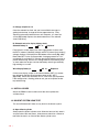
THE SOLENOID +THE PID CONTROLLER
The PRISM 2 Solenoid is controlled by state-of-the-art PID Control loop feedback circuitry (The
Controller). The PID Controller makes calculations based on an error value which is calculated as the
difference between a measured process variable (how much oxygen is in your loop) and a desired
setpoint (the O2 setpoint). It also considers the history of what has occurred previously, and makes
predictions about what may occur in the future, constantly making adjustments to it’s algorithms
accordingly. Sometimes called a “Three Term Controller”, the P, I and D stands for Proportional - Integral
- Derivative.
A familiar example of a control loop is the action taken when adjusting hot and cold faucets (valves) to
maintain the water at a desired temperature. This typically involves the mixing of two process streams,
the hot and cold water. The person touches the water to sense or measure its temperature. Based on
this feedback they perform a control action to adjust the hot and cold water valves until the process
temperature stabilizes at the desired value.
The sensed water temperature is the process variable or process value. The desired temperature is the
setpoint. The input to the process (the water valve position) is the variable. The difference between the
temperature measurement and the setpoint is the error and quantifies whether the water is too hot or too
cold and by how much.
After measuring the temperature, and then calculating the error, the controller decides when to change
the tap position and by how much. When the controller first turns the valve on, it may turn the hot valve
only slightly if warm water is desired, or it may open the valve all the way if very hot water is desired. This
is an example of a simple proportional control. In the event that hot water does not arrive quickly, the
controller may try to speed-up the process by opening up the hot water valve more-and-more as time
goes by. This is an example of an integral control.
Making a change that is too large when the error is small is equivalent to a high gain controller and will
lead to overshoot. If the controller were to repeatedly make changes that were too large and repeatedly
overshoot the target, the output would oscillate around the setpoint in either a constant, growing, or
decaying sinusoid. If the oscillations increase with time then the system is unstable, whereas if they
decrease the system is stable. If the oscillations remain at a constant magnitude the system is marginally
stable.
In the interest of achieving a gradual convergence at the desired temperature, the controller may wish to
damp the anticipated future oscillations. So in order to compensate for this effect, the controller may elect
to temper its adjustments. This can be thought of as a derivative control method.
15 |
In theory, a PID controller can be used to control any process which has a measurable output, a known
ideal value for that output and an input to the process that will affect the relevant process value. PID
controllers are used in industry to regulate temperature, pressure, flow rate, chemical composition,
speed and practically every other variable for which a measurement exists.
A Typical Solenoid Loop Feedback Circuit*
*Source: Wikipedia
| 16
PART 1 . SECTION 2
If a controller starts from a stable state at zero error, then further changes by the controller will be
in response to changes in other measured or unmeasured inputs to the process that impact on the
process, and hence on the process variable. Variables that impact on the process other than the
manipulated variable are known as disturbances. Generally controllers are used to reject disturbances
and/or implement setpoint changes. Changes in feed water temperature constitute a disturbance to the
faucet temperature control process.
BUCKET SEALING O-RINGS
There are two bucket sealing O-rings (Fig. 1.24) for redundant sealing of
the breathing loop. Standard user maintenance during system set-up and
tear-down are required.
BUCKET LATCHES
Fig. 1.24
There are 3 Nielson Sessions 300 series Stainless Steel locking latches
mounted on a stainless steel band (Fig. 1.25) that hold the bucket securely
onto the head assembly. While two latches will hold the bucket securely, it
was felt that redundancy here was critical.
BASKET SPRING ON BUCKET
Fig. 1.25
The absorbent basket is pressure-sealed onto the Red CO2 Seal under
the head by the bucket spring assembly (Fig. 1.26) at the bottom of the
bucket. The spring creates the seal between the basket and Red CO2 Seal
and also reduces vibration on the basket during transit.
WARNING: Proper spring tension is critical for safety and
an effective seal. One thread should be exposed above the
locknut as shown. Further instructions are available in the
User Service Guide doc. 12-4091.
Fig. 1.26
ABSORBENT BASKET ASSEMBLY
The absorbent basket is comprised of six pieces (Fig. 1.27). The basket
outer cage that supports the nylon absorbent-retaining mesh, a screw-in
center tube and O-ring. It also supports the nylon mesh and a screw-on
cover. Two foam pads must be installed top and bottom prior to filling the
absorbent basket. The bottom pad has a larger center diameter hole than
the top pad. The foam pads impede the flow of gas against the smooth surfaces of the basket top and bottom, hindering any potential gas channeling
in these areas.
The gas flow vanes built into the top of the scrubber basket create an area
of increased gas velocity within the O2 sensor area of the head, reducing
the dew point of the gas around the O2 sensors. The reduction in condensing humidity in this critical area helps reduce the potential for water to
condense on the surface of the hydrophobic membrane of the O2 sensor.
17 |
Fig. 1.27
PART 1 . SECTION 2
BACKPLATE
The Hollis PRISM 2 can be outfitted with any industry standard technical
style backplate. The unit is currently shipped from the factory with a Hollis
Aluminum Backplate and Solo Harness (Fig. 1.28). The style of threading,
for the webbing on the backplate, is left to user preference.
O2 + DILUENT FIRST STAGES
All PRISM 2 first stages (Fig. 1.29) have been oxygen cleaned and assembled in a clean room environment with specially designed materials,
halocarbon-based lubricants and color-coded for easy identification on
and off the PRISM 2 chassis (green=O2, Black=Dil). In non-CE countries,
they come outfitted with 300 BAR/4500 PSI DIN connections and custom
designed port blocks with 4 low pressure and 1 high pressure ports. The
custom design does away with the need to add in failure points such as
hose swivels. The working Intermediate pressure of both first stages is 140
to 145 psi / 9.7 to 10 bar.
All First stages are equipped with pressure relief valves (Fig. 1.30). The
valves reduce the likelihood of an uncontrolled increase in intermediate
pressure causing a free-flow of gas into the breathing loop. The first stage
pressure relief valve is not a user serviceable part.
Fig. 1.28
Fig. 1.29
The oxygen feed lines to the solenoid and manual O2 addition valve incorporate in-line flow restrictors to meter the flow of oxygen into the breathing
loop. The restrictors must not be removed.
GAS CYLINDERS
The Hollis PRISM 2 will accommodate most sizes of cylinders commonly
used on rebreathers.
Fig. 1.30
| 18
fitting your prism 2
Your PRISM 2 rebreather should be fitted to you with the same attention as
you would any other fine (and very expensive) custom-made piece of clothing. A properly fitted rebreather will perform more consistently with better
all around breathing characteristics, have less hydrostatic imbalances in all
diving positions, less strain and fatigue on spinal musculature and better
diver trim while diving.
The fitting process begins before you even set-up the PRISM 2. First you
must assess your body type, as that will give you a starting place for making close approximations to what will be the final, best fit.
The standard counterlung yoke fits a wide range of body types, and generally anyone between 5ft to 6ft tall with a standard torso will find a best fit
using the standard counterlung yoke. At the upper ranges of that measurement, a person with a long torso, or anyone taller than 6’ will probably find
that the Long yoke works best for them. If you have any questions, or need
help finding which set-up works best for you, ask a PRISM 2 Instructor, or
go into your local Hollis dealer. They will be more than happy to help you
get your rebreather properly fitted.
Once you have decided which yoke should work best, you will begin testing out the different variables such as backplate position (2 available), Wing
position (3 available) and three positions on the yoke, which will dictate
where the counterlungs sit on your chest.
First look at the backplate. The harness webbing should be adjusted so
the top of the backplate plate sits about 4 to 6 inches / 10.2 to 15.2 cm or
so below your shoulders. Next, put the counterlungs on the yoke. Take the
assembly and put it on so the yoke hangs over the backplate while holding the counterlungs on your chest. The center of the DSV/BOV assembly
breathing hose holes should be level with your collar bones.
Proper fit is the first element in a rather complex dance with physics. These
few pointers should give you a good starting place in custom fitting the
Hollis PRISM 2 for best fit. Don’t be afraid to experiment with placement as
the ultimate goal is diver comfort. Once you have a fit that you feel will work
for you in the water, we need to examine how and where to distribute any
weight you will require to get you the best in-water “stability” possible.
19 |
PART 1 . SECTION 3
STABILITY
article BY GERARD NEWMAN
What is stability? Briefly, it’s the ability to choose and maintain your
position in the water column. When we have a stable platform for diving we are more comfortable, in better control and better able to observe
our underwater surroundings. Diving with a CCR adds some additional
considerations for stability. Ideally, we should be stable when swimming
(dynamic stability) and when hovering (static stability). We have better
control over our stability when we assume prone (horizontal) trim in the
water with our fins flat. This increases our vertical drag (helping to maintain our vertical position in the water column) and decreases our horizontal
drag (as when swimming) (Fig. 1.31).
Stability is affected by weighting and buoyancy. Our weighting components include the cylinders we choose to dive with, lights, fins, backplates
and lead ballast that we carry with us. These components may be distributed from side to side and head to toe. Improper distribution will result in
non-horizontal trim. Too much lead at our waist will tend to drag our hips
down resulting in a head-up position in the water (Fig. 1.32). Fins that are
too light will result in a feet-up position. Divers often instinctively compensate for weight placement problems by arching their backs to maintain
trim. The objective is to allow proper trim with a relaxed posture in the harness. Of course proper weighting is key – we should be able to maintain
a 10 foot stop with no gas in the wing and a comfortable amount of gas
in our exposure suit (when diving a drysuit). With the CCR we have to
account for the gas volume in our breathing loop. I typically recommend
starting with an extra 4 lbs over what the diver would normally wear with a
single tank open circuit rig as a starting point. Divers with larger or smaller
tidal volumes will need to adjust accordingly.
Our buoyancy components include our exposure suit, our wing, and our
counterlungs. Minimizing the gas volumes in each will go a long way
towards minimizing the effects of Boyle’s Law. The larger the gas bubble,
the harder it is to control. The shallower you are, the more pronounced
the effects of Boyle’s Law – careful attention to controlling the gas volumes
in our counterlungs, wing and our exposure suit on ascent is critical. Adding or removing small amounts of gas and allowing time for the change to
take effect is the key to controlling our buoyancy (Fig. 1.32 & 1.33).
Fig. 1.31
Fig. 1.32
Fig. 1.33
| 20
Counterlung position should be such that they are as close to your lungs
as possible, both in the vertical and horizontal planes (Fig. 1.34). This
will minimize static lung loading and decrease the work of breathing. The
bottoms of the counterlungs should be secured to the waist strap to hold
them in place when they are inflated and become buoyant. For most divers the elbows on the counterlungs should be positioned at the collarbones, with the chest strap tightened to control their horizontal position.
Gas volume in the counterlungs will affect both your buoyancy and trim.
Too much gas in the counterlungs will result in head-up trim; too little will
result in head-down trim (and difficulty taking a full breath). With practice
one can become proficient at adding and removing gas from the breathing loop to maintain horizontal trim and neutral buoyancy.
Fig. 1.34
The wing may be positioned to increase buoyancy towards our head or
our feet if needed to adjust our trim. Weights can be placed near the
shoulders to provide a counterbalance to the counterlungs and help keep
us prone in the water with minimal effort.
The backplate should be positioned such that the top of the plate is easily reachable with the tips of your fingers if you swing your arms back
with your elbows next to your ears. On most people this will position the
backplate at the top of the scapulas. Straps should be loose enough to
allow full range of movement of your arms across the chest and allow you
to “chicken wing” into and out of the harness. The crotch strap should
be adjusted to keep the rig stable – tight, but not too tight. If the crotch
strap is pulling the waist strap down then it is too tight and needs to be
lengthened (Fig. 1.35).
A very helpful technique is to have someone shoot some video of you
while hovering and while swimming. Reviewing this video can help identify where your buoyancy or trim needs adjusting. A good Intro to Tech
instructor can also be very helpful.
21 |
Fig. 1.35
setup
AN O-RING CLEANING PRIMER
PART 2 . SECTION 1
O-Rings are an integral component of almost every part of a functioning
rebreather and as such, you must be adept at properly inspecting
and caring for them. For the sake of brevity we will give you a generic
description of how to prepare the O-rings in the Hollis PRISM 2 for use,
below. In the checklist “step-by-step” to follow, unless there are unusual
design, access, or handling considerations for a particular O-ring, we will
simply state,
“Remove, clean and prepare the O-ring(s), O-ring groove and mating
surface for use, or replace if worn or damaged.”
Remove the O-ring from the O-ring channel using a non-metal O-ring
removal tool (Fig. 3.1) being careful not to over-stretch the O-ring. Never
use a sharp metal O-ring pick or any metal object as that can damage the
O-ring, the O-ring groove or O-ring mating surface.
NOTE: O-RING REMOVAL TIP
While squeezing opposite sides of an O-ring, slide both sides in the same
direction. This will create a protrusion of the O-ring on that side that you
can grab with your fingers, to roll it out of the groove. If necessary, the
tapered end of a plastic Zip Tie can be used to help pull an O-ring up and
out from its groove.
Clean the O-ring with a soft, dry lint-free cloth, (Fig. 3.2) being careful to
remove any debris and old lubricant. Run your fingers around the O-ring
feeling for uneven surfaces, abrasions, sand or other debris that could cut
the O-ring. If you see or feel any damage, replace the O-ring. Never dive
with a damaged O-ring, as a flood may result.
Fig. 3.1
Fig. 3.2
Clean the O-ring channel and area surrounding the channel of debris and
old lubricant (Fig. 3.3). Place a small amount of lubricant on your finger
and coat the O-ring lightly. Inspect the O-ring to make sure there is no
debris, lint or hairs on it. Carefully replace the O-ring in its cleaned O-ring
channel.
Make sure to clean the O-ring’s mating surface (the surface the O-ring
seals against) of all lubricant, dirt and lint.
Fig. 3.3
| 22
PACKING THE PRISM 2 CO 2 SCRUBBER
To pack your PRISM 2 scrubber, you will need the following items:
(Fig. 3.4)
• 1 towel
• Paper towels or newspaper sheets
• 1 ea. top and bottom absorbent basket foam pads
• Approximately 6 lbs (2.7 kg) fresh unused 8-12 CO2 absorbent
• 1 pair surgical gloves
• 1 painter’s or surgical mask
• 1 eye protection
Fig. 3.4
The PRISM 2 scrubber is easy to pack, and with experience should
only take 5 to 10 minutes from set-up to clean up.
Find a dry area away from and downwind of other people. If necessary,
take a moment to let people around you know that you will be working
with caustic materials, and request they stay upwind from where you will
be working.
Before handling the caustic CO2 absorbent, put on your personal
protective gear including gloves, breathing mask and eye protection.
A dive mask may look silly, but works quite well as eye protection.
WARNING: If you ever ingest CO2 absorbent due to handling mishaps or a
loop flood, known as a “Caustic Cocktail”, immediately seek emergency
medical treatment and drink copious amounts of water. DO NOT INDUCE
VOMITING unless instructed to do so by medical professionals. (For more
information download the latest Material Safety Data Sheet from the product manufacturer, or contact your local Poison Control Center.)
23 |
PART 2 . SECTION 2
Spread out a towel or other soft covering on the ground in a flat area, and
lay a few sheets of paper towel or newspaper on top of that. Place the
bottom foam pad (larger center hole) in the basket making sure it lays
flat against the bottom and sides of the basket (Fig. 3.5). Take a piece of
paper, golf ball or absorbent container cap and cover the top of the center
tube. This will keep absorbent from going down the center tube as you
pour it into the scrubber basket. (Fig. 3.6)
Fig. 3.5
Pour the absorbent slowly from about 12” above the basket, allowing the
wind to carry off any dust. The absorbent should be granular and not produce much dust while pouring (Fig. 3.7). If the material looks crushed or is
exceptionally dusty, don’t use it, as that can be an indication that the absorbent has been mishandled and may not scrub CO2 properly during a dive.
Continue pouring until the absorbent reaches the first horizontal brace on
the basket (Fig. 3.8). Unless you were exceedingly careful, some material will have fallen onto the paper around the basket. Lift the basket off the
paper and pour the granules from the paper into the basket. If the material
on the paper is mostly dust, dispose of it carefully rather than pouring it into
the basket.
Fig. 3.6
Fig. 3.7
Fig. 3.8
| 24
With the basket on the towel-covered ground, gently begin tapping the basket where the vertical and horizontal braces meet (Fig. 3.9). This will begin
to settle the granules in the basket. The trick is to tap hard enough on the
cross braces that the vibrations cause the material to settle, but not so hard
that the granules jump around. Make sure you do not tap the mesh as that
will only displace the material from the sides.
While tapping the cross braces, rotate the basket so you tap all sides of the
basket. Spend at least a minute tapping the basket sides. You may notice
that the absorbent level drops as the granules settle.
Repeat the filling process up to the second horizontal brace, then tap to
settle the granules as before. Repeat the filling process to the top of the
bucket, leaving a small hill of absorbent on the top (Fig. 3.10). Tap and
settle the material as before. You will probably be ably to settle this material
until it is almost level with the basket top.
Fig. 3.9
Fig. 3.10
Once the basket appears to be full, pour a few extra mound of absorbent
onto a cup or other small container and put it aside.(A mask box works
well!) Remove the material you used to block the center tube.
Lay the top foam pad (smaller center hole) on top of the mound of absorbent, and place the basket cover on top of the foam pad (Fig. 3.11).
Slightly tighten the basket top onto the first threads. Do not force the top
on. If you cannot easily start the top onto the basket threads, remove a bit
of absorbent and try again.
Once you have started the top onto the basket threads, clean the towel of
loose absorbent, then pick up the basket by the top horizontal brace and
using your thumbs to hold the basket and top together securely, lift the
basket a few inches above the ground and tap the basket slowly and firmly
3 times on the towel covered ground (Fig. 3.12). Never tap the basket on
uncovered ground, as that can damage the basket to exhale plenum sealing surface (Fig. 3.13). The sealing area on the basket must be kept clean
of caked-on absorbent, so don’t tap the basket down on loose absorbent.
Doing so will just make extra work and make any
post-packing scrubber basket cleanup take longer.
Fig. 3.11
Fig. 3.12
WARNING: Resist the urge to blow on the
packed basket to get rid of dust, as the dust
will get in your eyes, nose and throat.
Fig. 3.13
25 |
Once you have tapped the basket 3 times on the ground, turn the
basket top until in makes contact with the absorbent. Do not force the
top! Tap 3 times again and turn the top. Repeat this process until the
top is sealed completely on the threads.
Using the 3 tap and turn method will insure that you do not overpack the
bottom of the basket while leaving the top material loose. Also, making
a repeatable process your habit will insure that all you are packing your
scrubber consistently. Arbitrary methods lead to arbitrary results!
Remove the top and foam pad, and using more of the absorbent you set
aside on the paper, refill the basket until you again have a small mound of
absorbent on the top. Replace the foam pad, seat the top onto the basket
threads, and repeat the process.
NOTE:
There is no set
number of times you
will need to remove
the basket top to
add material, but
spending more time
settling the material
as you fill the basket
will help reduce it.
Once you have fully seated the top onto the basket a second time, check
the firmness of the material. The top and bottom of the basket should be
equally firm and you should not be able to displace absorbent grains by
applying moderately firm pressure against the mesh. If the top is not as
firm as the bottom, turn the basket upside down and tap three times on
the basket top. If the material is still loose or unevenly packed, open the
basket, add some more absorbent and repeat the process then check
firmness again.
Once the basket is packed to your satisfaction, use a clean paper towel
to carefully remove any dust collected on the outside of the basket.
Collect any left over absorbent that you had set aside for packing and if
it is not dusty, you may pour it back in the absorbent container. Seal the
absorbent container and store it in a cool, dry place.
| 26
PART 2 . SECTION 2
3 TAPS THEN TURN
PRE-PACKING THE PRISM 2 SCRUBBER
While pre-packing the scrubber well in advance of a dive, or transporting
packed scrubbers is not advised due to potential absorbent settling
issues, we recognize there are instances where packing a scrubber onsite is either impractical or impossible.
If you will not be using the packed scrubber immediately, put the basket
in an airtight container and seal the container. Put tape across the seal
on the outside of the airtight container and write your name, the date you
packed the basket, and the absorbent material used (Fig. 3.14). Since
this is a fresh fill write “0 hours used” on the tape. Store the container in a
cool, dry place. After short-term storage or transportation, you must check
the scrubber for settling or loose scrubber material prior to installing it in
the rebreather.
CLEANING YOUR EMPTY SCRUBBER
After use, it is always a good idea to wash and dry the scrubber basket,
basket pads and bucket to remove residual dust and used absorbent.
Use fresh water and make sure to wash out any loose granules.
Fig. 3.14
NOTE:
To avoid damage,
use only factory
tested cleaning
solutions. See list of
approved cleaning
solutions in the PART
5 Section 2 for further
information.
If you notice that the threads of the basket or top are becoming clogged
by crushed, caked absorbent dust or the absorbent is beginning to cakeup (Fig. 3.15), you will need to soak the top and basket threads in white
vinegar for 15 to 30 minutes, which will dissolve the caked on absorbent
and return the basket to like-new condition. Heating the vinegar to 120
°F/49 °C will make it work faster, but will make you unpopular with anyone
close by. Wash the cleaned parts thoroughly with fresh water until the
smell of vinegar is completely gone.
DISPOSING OF USED CO2 ABSORBENT
You have probably heard that used absorbent is simple calcium
carbonate, the same stuff seashells and reefs are made from. Eventually
that will be true, but even spent absorbent is still highly caustic and will
be for some time. Never dump freshly spent absorbent in the ocean! It is
best to find a covered pail or a garbage bag in which to store the spent
material, and mark the container as containing a caustic substance.
27 |
WARNING: If you do need to store the scrubber or transport
it to your dive site, YOU MUST check the scrubber basket for
absorbent material settling prior to inserting it in the rebreather. If the absorbent seems loose at all, top-off the basket with
additional absorbent prior to use. Failure to insure a properly
packed scrubber may lead to injury or death.
Fig. 3.15
USING CHECKLISTS
PART 2 . SECTION 3
THE IMPORTANCE OF USING YOUR CHECKLISTS
Imagine you are sitting on a commercial airliner watching the pilot
ready the plane for takeoff. The copilot turns to the captain and asks
if he is ready to go through the pre-flight checklists. The pilot does a
cursory scan of the cockpit, turns to the copilot and says, “Everything
looks good to me, we can skip them”. How comfortable would you
feel flying at 32,000 feet with that captain at the controls?
CASE STUDY OF A CLOSE CALL
A rebreather diver, self-described as being “very experienced” with his
rebreather, has completed two 1½ - hour dives. He changes out the
scrubber with fresh absorbent to complete a third 2-hour dive later in the
day. He reports that he was feeling “rushed” because he was delaying
his buddies from lunch. After quickly re-packing the scrubber, relying on
memory instead of his checklist, he reassembles the rebreather and then
joins his buddies.
An hour after lunch, he dons the rebreather and enters the water. After
completing his 15 ft checks, he descends to 35 feet whereupon he begins
to feel short of breath. Still clear-headed enough to realize this could
possibly be a sign of CO2 toxicity, and deciding to err on the side of
caution, he bails out to open circuit and aborts the dive.
NOTE:
Don’t allow yourself
to become rushed or
distracted when setting up or working
on your rebreather.
An inattentive
rebreather diver is
an accident waiting to happen. Take
your time while
setting up your
rebreather and when
diving.
Once safely back, the diver disassembles the unit and finds that an O-ring
sealing the breathing loop is missing, allowing his exhaled gas to bypass
the scrubber completely and enter the inhalation side of the rebreather.
Fortunately, due to his quick actions, this incident resolved without
tragedy.
WARNING: The importance of working with checklists when
setting up your PRISM 2 cannot be overstated! If you have not
set-up your PRISM 2 using the checklists, DO NOT dive the
rebreather.
| 28
LESSONS LEARNED
In his on-line report, the diver stated he had learned a hard lesson from
this life threatening incident. The first and most obvious was he had not
followed his training, relying on his memory instead of using the checklist.
He also reported that “to be honest”, this was not the first time he had
skipped using a checklist. He vowed never to make that mistake again.
WHY A MULTIPLE LIST FORMAT
One thing that became clear to us as we talked to rebreather divers about
their use of checklists was that a simple, one-size-fits-all checklist often
does not follow the stages in which they normally set-up their rebreathers.
The checklist becomes an encumbrance to safety if divers have to skip
around the checklist, checking off only those items needed to get to the
next phase.
For instance, some divers set-up and test their rebreather days in
advance of the dive, and leave the rebreather assembled during transport
to a dive site. A start to finish checklist may not take into account the
checks required once the unit arrives at the site.
We have broken the PRISM 2 checklists into 4 distinct sub-lists which
should follow the steps encountered in the majority of real world diving
situations.
29 |
NOTE:
It is always recommended that you
do a full set-up and
“pre-dive” check before any trip, as that
is the only sure way
to verify all systems
are fully functional.
PART 2 . SECTION 3
To follow is the group of 4 “expanded” checklists, which includes the
incremental steps you need to complete each step on the checklist.
The lists are broken out as follows:
“PRISM 2 Component Inspection”, “PRISM 2 Assembly Order”
and “PRISM 2 Operational Checklist”. The fourth sub-section of the
operational checklist, “Immediate Pre-Dive Checks & System Settings”
are for final “systems go” verifications prior to entering the water.
You can use the 3 main sections individually as follows:
PRISM 2 Component Inspection:
This section of the checklist is used to help you verify that all parts of a
complete PRISM 2 are present and visually undamaged prior to packing
it for transport. There is nothing worse than boarding a local dive boat or
landing in a foreign country just to find out that you left your DSV/BOV in
your dive locker back home.
PRISM 2 Assembly Order:
This is the list you will normally use to “build your rebreather” from its
component parts.
PRISM 2 Operational Checklist:
This is the checklist you will use to test all assembled components of the
rebreather to make sure they are functioning properly as a whole prior to
entering the water. You will complete these steps after assembly, or if a
piece of the functioning rebreather has been disassembled at any time.
This is the most critical part of the entire set up process, since a nonfunctional rebreather will always become evident at some point as you
go through the operational checks. Do not dive the rebreather if it has not
passed every step of this checklist.
Immediate Pre-Dive Checks & System Settings:
These are the final few checks done with the unit secured to your body
before jumping in the water. While most checks are verifications of
previously checked items, it is absolutely imperative that you check these
again before entering the water.
| 30
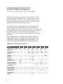
COMPONENT INSPECTION Checklist
KEY:
W = WEAR / O = OPERATION / I = INSTALL
1. C
heck H-Plate / Harness / BC for Wear,
Damage or Missing Parts
A. H-Plate
B. Harness (W)
C. Fabric (W)
D. Inflator / Alt. Air Source (O)
E. Dump Valve(s) (O, W)
F. Removable Weight Pockets (W, I)
G. Fastening Clips (W)
2. Inspect Counterlungs
A. Fabric (W)
B. Drains (O)
C. T
hreaded DSV/BOV Assembly Rings (W)
D. Breathing Hoses, Oetiker Clamps,
+ O-Rings (W)
E. O2 Addition Valve (I, O)
F. Automatic Diluent Valve (ADV) (O)
G. Over-Pressure Valve (OPV) (O)
3. Inspect DSV/BOV Breathing Hoses
A. Hoses,
B. Oetiker Clamps (W)
C. O-Rings (W)
D. Inhalation Hose Mushroom Valve
(only on inhale hose for DSV supplied systems) (O, W)
4. Inspect DSV/BOV
A. Shut-Down/OC Assembly (O)
B. Water Drain (O)
C. Mouthpiece, Zip-Tie
D. D
SV/BOV Exhalation Mushroom Valve (O,W)
E. Inhalation Hose Mushroom Valve (only on
inhale side of BOV) (O, W)
5. Inspect Regulators + Hoses
A. 1st Stages (W)
B. Pressure Relief Valves
C. LP Hoses + Connectors (W)
D. HP Hoses + Connectors (W
E. Diver Installed Gas Supply Hoses
(if installed)
F. Pressure Gauges
31 |
6. Inspect Wiring
A. Heads Up Display (W)
B. Wrist Display (W)
7. Battery Compartment, Batteries
+ O-Rings
A. Solenoid Batteries (I)
B. Heads Up Display Battery (I)
C. O-Rings (2) (W)
D. Cover, Cover Latches + Keepers (O,W)
8. Solenoid Operation (O)(If proceeding
immediately to assembly and operational
checks, you can skip this step.)
9. Inspect Head Assembly
A. Red CO2 Seal (I, W)
B. Head To Bucket O-Rings (2) (W)
C. O-Ring Seats (W)
D. Latch Keeper (W)
E. Nut Bars, Head Bolts, Head Cover Bar +
Head Cover (W, I)
10. Oxygen Sensors
A. 3
Oxygen Sensors + Sensor Holders Installed (I)
B. Oxygen Sensor Wiring Harness (I)
C. mV Readings Within Range(O)
(8.5 mV to 14 mV in air)
11. Bucket Assembly
A. Basket Compression Spring + Pad(I)
B. Latches (3) (W, O)
C. 1 Moisture Pad (I)
12. Basket Assembly
A. Check Mesh (W)
B. Center Tube O-Ring (I)
C. Top + Basket Threads Clean (O)
D. Top + Bottom Foam Pads (I)
COMPONENT INSPECTION Checklist: DETAILS
PART 2 . SECTION 4
KEY:
W = WEAR / O = OPERATION / I = INSTALL
1: CHECK H-PLATE / HARNESS / BC FOR WEAR, DAMAGE,
OR MISSING PARTS: 7 STEPS
A: H-Plate
Look for any bent or broken parts on the H-plate. Verify that the rubber cylinder pads are in place on the cylinder rests. Check the cylinder
bands for wear.
B: Harness (W)
Check the webbing for excessive wear. Check D-rings, buckle, crotch
strap and any diver installed hardware such as knives or equipment
pouches are present and in working order.
C: Fabric (W)
Lay the BC down flat and inspect the fabric for any tears or signs of excessive wear. Pay special attention to areas around inflators and areas
that experience chaffing during use. Never dive the rebreather with a
buoyancy compensator that is not in good condition.
D: Inflator (O/W)
Depress the inflator and deflator buttons feeling for smooth actuation.
If there is any binding or sticking of either button this usually indicates
that salt has dried inside the mechanisms. Dried salt can abrade O-rings
and cause slow leaks. If you do find that the inflator buttons stick on first
actuation, clean with fresh water or repair as needed.
You will complete a pressurized test of the inflator later on in the operational
checks. However, it is always a good idea to test each component, but
especially important if you find that the buttons have been sticking. Finally,
partially inflate the buoyancy compensator by manually blowing air into
the valve (Fig. 3.16) while depressing the deflator button. Check that the
buoyancy compensator is holding air and not leaking. Do not deflate the
buoyancy compensator – See step E: Dump Valves.
Fig. 3.16
| 32
E: Dump valve(s) (O, W)
Inspect the buoyancy compensator dump valves. Momentarily open
each valve and let a bit of air from the buoyancy compensator out to
make sure they open and close freely. Also inspect the air dump pull
cords (Fig. 3.17) to make sure they are in good condition and not
entangled.
F: Removable weight pockets (W, I) (If Installed)
Verify that you have 2 weight pockets (Fig. 3.18). Check that their
Velcro flaps, quick-lock and the pull handles in good working
condition. Secure them in place.
Fig. 3.17
G: Fastening clips (W)
Check for broken or cracked parts in the following areas:
1.) Waist strap (Buckle)
2.) Large counterlung retainer clips attached to waistband
(male Fastex) (Fig. 3.19)
3.) Small lateral counterlung adjusting straps (male Fastex) (Fig. 3.20)
Fig. 3.18
NOTE:
Integrated weight
pockets are one of
the most frequently
lost or left behind
pieces of dive gear!
Do you know where
your weight pockets
are?
Fig. 3.19
Fig. 3.20
33 |
PART 2 . SECTION 4
2: INSPECT COUNTERLUNGS: 7 STEPS
A: Fabric (W)
Lay the counterlungs out and inspect the fabric for tears or obvious
signs of abnormal wear. While the counterlungs are quite robust, you
must never dive with counterlungs that show signs of excessive wear
or damage, as counterlung integrity failure during a dive would cause
immediate and catastrophic flooding of the breathing loop. Shake the
counterlungs to make sure no foreign objects have entered the counterlung during storage or transportation. Smell the inside of each counterlung. They should not have any distinct odor.
B: Drains (O)
Unscrew the locking collar and actuate the valve by depressing the
nipple inward toward the body of the valve (Fig. 3.21). Blow into the
valve to make sure it is not clogged or broken. The valve should pop
back out when you let go of the valve. If it does not, it must be replaced.
Re-tighten the locking collar.
Fig. 3.21
NOTE: THE SNIFF TEST
Sniff the air inside of the counterlung. It should smell clean and possibly
have a hint of sanitizer smell to it. This is normal when using Hollis
approved breathing loop cleaners, however a distinct smell of sanitizer
is not normal and is probably due to inadequate rinsing after cleaning.
| 34
C: Threaded DSV/BOV assembly rings (W)
Check for cracks and thread stripping. The hose mounting rings
(Fig. 3.22) are welded to the counterlungs. Make sure the rings are
firmly attached to the counterlung fabric.
Fig. 3.22
D: Breathing hoses, Oetiker clamps & O-rings (W)
Check the counterlung-to-head hoses for holes, wear or age cracking
(Fig. 3.23). Stretch the hose slightly and inspect the rubber material.
If you can see separation or light spiderweb cracking in the rubber, it
is beyond it’s serviceable life and must be replaced. Never dive with
breathing hoses that show signs of rubber aging, as immediate and
catastrophic loop flooding will occur if the hoses fail during diving.
Wipe the interior surface of each breathing hose with a clean, dry towel
then look at the spot on the towel where you wiped the hose interior. If
the towel has foreign particles or dirt on it, re-clean the counterlung and
hose using a bottle brush (Fig. 3.24) to remove any foreign material
in the hose corrugations. See PART 4 Section 2 for further cleaning
instructions.
The counterlung-to-head attachment hardware has an O-ring seal
(Fig. 3.25). Remove, clean and prepare the O-ring(s), O-ring groove
and mating surface for use, or replace if worn or damaged. Also at
this stage you will want to make sure there is no debris in the hose
connection at the head (Fig. 3.26). Locate the two hose connections
in the head and run your finger inside them. If you feel any debris,
clean the inside with a lint-free cloth. If there was any debris on the
exhalation side head connector, especially old absorbent particles,
some absorbent may have fallen into the head plate area (Fig. 3.27),
which is located on the underside of the head. Clean out any debris
that may have collected in the head plate area prior to unit assembly. If
you hear grinding when turning the hose nut, sand or grit has collected
between the nut and hose connector. Dip the hose nut and connector
in a bucket of water and gently tap the hose nut against the bucket wall
to remove the sand.
Fig. 3.23
Fig. 3.24
Fig. 3.25
Fig. 3.26
Fig. 3.27
35 |
PART 2 . SECTION 4
E: O2 Addition valve (O)
Check the oxygen addition valve on the exhale counterlung for tightness by holding the base of the valve from the back of the counterlung
through the counterlung fabric and attempt to tighten (twist clockwise)
the threaded nut (Fig. 3.28). There should be no movement. If the valve
has come slightly loose, hand tighten the nut as needed until it will not
turn further. Activate the valve button to make sure it operates smoothly.
It should not feel stiff or difficult to depress. You will check the valve
again for proper operation during your operational checks. See the User
Service Guide doc. 12-4091 if the button does not move freely.
Fig. 3.28
F: Automatic diluent addition valve (ADV) (O)
While holding the counterlung, depress the valve body until you feel
the plunger move (Fig. 3.29). It should move freely. (You will check the
valves automatic and manual addition of diluent into the breathing loop
during your operational checks.) For a closer inspection, or if you think
the valve may be damaged, you can unscrew the valve body from the
counterlung by turning the nut counter-clockwise until the valve comes
loose from the lung.
Fig. 3.29
G: Over-pressure valve (OPV) (O)
The over-pressure valve is located on the exhale counterlung slightly
below the threaded DSV/BOV hose opening (Fig. 3.30). Rotate the body
open and closed. You should feel a slight ratcheting as you twist the
body. Rotate the OPV body clockwise until it is fully closed in preparation for the oxygen flush during your operational check.
Fig. 3.30
| 36
3: INSPECT DSV/BOV BREATHING HOSES: 4 STEPS
A: Inhalation & exhalation hoses (W)
While holding the hose by the threaded hose nuts, gently stretch them
to insure the ends are secure. If there is any movement, check the hose
clamps and hose material next to the clamps (Fig. 3.31) for wear or
tears.
Fig. 3.31
While continuing to stretch the hose, look along the hose length at the
rubber for signs of wear or age cracking. If you see signs of abrasions or
spider web cracking, the hose must be replaced. Never dive with breathing hoses that show signs of rubber aging, as immediate and catastrophic loop flooding will occur if a breathing hose tears during diving.
B: Oetiker clamps
Check to make sure the clamps are securely locked down onto the
hoses (Fig. 3.32) and then cover them with the silicone clamp covers so
they do not snag fabrics such as wetsuit material while putting on and
taking off the rebreather.
C: O-Rings (W)
There are two O-rings on each breathing hose assembly. You will find
the first O-ring under the counterlung elbow-retaining nut of each hose
assembly. Pull the elbow retaining nut back with your thumb and forefinger and using an O-ring pick, gently remove the O-ring from its groove.
Remove, clean and prepare the O-ring(s), O-ring Groove and mating
surface for use, or replace if worn or damaged.
The O-ring under the DSV/BOV threaded nut counterweight is a bit
trickier as you may not be able to fully retract the weighted nut to expose
the O-ring. However, you can remove the O-ring with an O-ring pick.
Pull the counterweight nut as far as back from the hose opening as possible. You should be able to see the O-ring. Carefully extract the O-ring
from its groove, making sure not to scratch the seating surface. Remove,
clean and prepare the O-ring(s), O-ring groove and mating surface for
use, or replace if worn or damaged.
37 |
Fig. 3.32
PART 2 . SECTION 4
To clean the O-ring groove, you can use a Q-tip (Fig. 3.34), but be careful not to allow cotton fibers to remain behind. If there are dirt particles
on the O-ring when you remove it from the groove, disassemble the
threaded counterweight side of the DSV/BOV hose assembly by removing the Oetiker clamp and thoroughly clean the O-ring groove.
D: Inhalation hose mushroom valve (O, W)
(only on inhalation hose for DSV supplied systems)
If your PRISM 2 is supplied with a DSV, the inhalation side breathing
hose will house a one-way mushroom valve (Fig 3.35). (The inhalation
mushroom valve on BOV supplied systems is housed in the BOV on the
inhalation side of the BOV body).
To test the sealing integrity of the valve, place the hose elbow on your
mouth and put the DSV counterweight in your other hand. While looking at the mushroom valve gently inhale. You should see the mushroom
valve seal around the outside surface of the 6-spoke mushroom valve
seat (Fig. 3.36). You should not feel or hear any air movement from the
valve. If you can inhale air, clean the mushroom valve and seat with water. If it continues to leak after cleaning, you must replace the valve (and
possibly the valve seat), then repeat the test.
If you remove the valve seat for inspection or repair, you must clean
and prepare the O-ring(s), O-ring groove and mating surface for use, or
replace if worn or damaged.
Fig. 3.34
Fig. 3.35
Fig. 3.36
| 38
4: INSPECT DSV/BOV: 5 STEPS
A: Shut-Down/OC assembly (O)
Open and close the DSV/BOV to make sure the inner barrel operates
smoothly and does not bind. If it is hard to open or close, or if you hear
a scraping sound during barrel movement, the DSV/BOV barrel and
housing will need to be cleaned and lubricated.
DSV: There are three sealing O-rings on the DSV rotating barrel
(Fig. 3.37). You will be checking the sealing of these during your positive and negative pressure tests. If any of these O-rings should fail, you
will need to service the DSV. Check the User Service Guide doc. 124091 for further information.
Fig. 3.37
BOV: The BOV barrel is a 2-position barrel with sealing O-rings much
like a DSV. You will be checking the sealing of these during your positive and negative pressure tests. If any of these O-rings should fail, you
will need to service the BOV barrel. Check the User Service Guide doc.
12-4091 for further information.
B: Water drain (O)
On the underside of the DSV/BOV you will see a small hole just under
the mouthpiece (Fig. 3.38). This is the water drain hole. Check to make
sure it is not clogged.
Fig. 3.38
Place the DSV/BOV in your mouth with the valve closed and blow into
the mouthpiece. You should be able to blow air through the drain hole,
but you will feel some back-pressure. If you cannot blow air through
the drain hole, debris may have clogged the hole or become lodged in
the drain channel in the rotating stainless steel sleeve. You will need to
service the DSV.
C: Mouthpiece, zip-tie
Check for holes or torn bite tabs in the mouthpiece. Replace as needed.
Check that the zip-tie retainer is present and holding the mouthpiece
securely onto the DSV/BOV.
39 |
PART 2 . SECTION 4
D: DSV/BOV exhalation mushroom valve (O, W)
Open the DSV/BOV to the CC position. Place your palm over the left
side opening of the DSV/BOV, fully blocking it, and attempt to gently
draw air in. There should be no air movement. If you are able to draw air
in, clean the exhalation mushroom valve and seat with water. If it continues to leak after cleaning, you must replace the exhalation side mushroom valve and seat, then repeat the test.
E: Inhalation hose mushroom valve (O, W) (only on inhale side of
BOV)
(BOV ONLY): Open the BOV to the CC position. Place your palm over
the right side opening of the BOV, fully blocking it, and attempt to gently
exhale. There should be no air movement. If you are able to exhale air,
clean the exhalation mushroom valve and seat with water. If it continues
to leak after cleaning, you must replace the exhalation side mushroom
valve and seat, then repeat the test.
5: INSPECT REGULATORS + HOSES: 6 STEPS
A: 1st stages (W)
Remove the cap on the first stage DIN valve and inspect the DIN fitting
for signs of previous water ingress such as discoloration or salt buildup
(Fig. 3.39) on the filter surface. If there are signs of water ingress, do not
dive the unit until the first stage, hoses and pressure gauges attached
to it have been serviced by a Hollis authorized repair facility. Failure to
properly maintain the first stages could result in a free-flow of gas into
the breathing loop and lead to serious injury or death. Verify that the DIN
valve’s tank O-ring is in place and clean. Replace it if there are any signs
of wear.
Fig. 3.39
B: Pressure relief valves
Check that the pressure relief valve (Fig. 3.40) is in place and the body
of the valve has not sustained any impact damage. You will verify that
the valve is sealed when you pressurize the first stage. Should the valve
activate and discharge gas, suspect a malfunctioning first stage. You
can verify if the intermediate pressure is outside of operating parameters
with an in-line pressure gauge outfitted with a low pressure QD fitting.
Fig. 3.40
| 40
C: LP (Low Pressure) hoses & connectors (W)
Check each hose leading from the first stages for signs of wear or age.
Replace as necessary only with Hollis approved parts. Check all LP
quick disconnect hardware for corrosion and verify that the Schrader
valve is clean of debris, salt or corrosion. If the QD fittings are becoming
stiff or are built-up with corrosion, a ½ hour soak in white vinegar may
remove the build-up.
WARNING: It is important to understand that all of the LP oxygen
supply hoses contain in-line flow restrictors, and must never get
exposed to salt water. Never replace an O2 side low or high-pressure hose with anything other than the correct Hollis part.
D: HP (High Pressure) hoses & connectors (W)
Check each HP hose leading from the first stages for signs of wear.
Replace as necessary only with Hollis approved parts.
E: Diver installed gas supply hoses (if present) (W)
If any other gas supply hoses are attached to the diluent first stage
such as a dry suit hose or second stage, check them for signs of wear.
Replace as needed.
F: Pressure gauges (O, W)
Look at both pressure gauges and verify that the needle is resting at
0 psi / 0 bar. If it is not, have the pressure gauge repaired or replaced.
Unless there are obvious signs of impact damage to the faulty gauge,
suspect water ingress through the first stage and have the rebreather
gas supply system serviced by an authorized Hollis repair facility. It is
especially important for the Oxygen side of the system to remain free
from contamination, as all parts must remain oxygen clean. (Refer to the
User Service Guide doc. 12-4091 for further information).
6: INSPECT WIRING : 2 STEPS
A: HUD (Heads Up Display) (W)
Check the Heads Up Display and wiring for damage. Turn the unit power on and verify that all three of the LED’s (Fig. 3.41) illuminate red then
green, once. If all three lights illuminate continuously orange for 30 seconds, the Heads Up Display battery must be changed. Once checked,
turn off the HUD. (See the HUD light states section of the PRISM 2
Displays and Electronics User Manual for display explanations.)
Fig. 3.41
41 |
Inspect Wrist Display and wiring for wear or damage. Turn on the Wrist
Display by depressing both the menu and select buttons (Fig. 3.42).
After the splash screen, the system will switch to the main information
screen.
Fig. 3.42
7: BATTERY COMPARTMENT, BATTERIES
+ O-RINGS: 4 STEPS (W)
A: Solenoid batteries
The solenoid runs on two 9V alkaline (Duracell® or equivalent quality
only) batteries wired in parallel and located in the battery compartment
of the electronics housing (Fig. 3.43). To check the solenoid voltage,
you will first need to make the wrist unit fire the solenoid at least once.
The easiest way to do this is switch the setpoint to one that has a higher
PO2 than ambient air.
If all readings on the wrist unit read “FAIL” you will need to calibrate the
wrist unit before it will fire the solenoid, see note below. With the wrist
display turned on from the previous step, depress the select button six
times until you see the bottom of the screen display the voltages for the
external battery (solenoid) and the internal battery (wrist display) (Fig.
3.44). A voltage above 7V, as reported by the Wrist Display, is considered by the electronics as acceptable. Therefore no dive should be conducted unless the voltage reported by the Wrist Display is greater than
7V. If the voltage is reported at or below 7V then both batteries must be
changed prior to conducting a dive.
EXT V
INT V
8.8
3.4
NOTE: Solenoid
Battery
For the computer to
measure the dynamic
load of the solenoid
battery, the PRISM
2 must have a valid
calibration stored
in memory to allow
the solenoid to fire.
If, when you turn on
the Wrist Display, all
three sensors display
“fail”, the solenoid
will not fire and the
voltage display for
the solenoid battery
will show “?”. You will
not be able to verify
the dynamic voltage
of the solenoid
batteries until the
system has been
calibrated, which
will then allow the
solenoid to fire.
Fig. 3.44
The computer measures the dynamic voltage of the solenoid batteries,
which means the voltage is being measured while the solenoid is firing
and the batteries are under load. This is the most accurate way to verify
the actual working capacity of the batteries. Using a voltmeter that does
not put a load on the battery can give you a higher voltage reading, but
the measurement will not be nearly as accurate a gauge of actual battery capacity. This is why we do not recommend relying on a voltmeter
to test the solenoid batteries.
Fig. 3.43
| 42
PART 2 . SECTION 4
B: Wrist Display (W)
B: HUD (Heads Up Display) battery
The HUD battery is located in the battery compartment. It is a SAFT 3.6V
AA battery.
C: O-Rings (2) (W)
There are two O-rings sealing the battery compartment. A “compression seal” O-ring sits inside the O-ring groove at the top of the battery
compartment (Fig. 3.45), and its mating face is the underside edge of
the battery cap. Remove, clean and prepare the O-ring(s), O-ring groove
and mating surface for use, or replace if worn or damaged.
Fig. 3.45
The second “Radial seal” O-ring resides in a groove on the inside edge
of the battery cap (Fig. 3.46), and its mating edge is the inside surface
of the electronics stack. Remove, clean and prepare the O-ring(s), Oring groove and mating surface for use, or replace if worn or damaged.
Fig. 3.46
D: Cover, cover latches & keepers (O, W)
The aluminum battery cap is held in place by two Nielsen Sessions
stainless steel locking latches (Fig. 3.47). Operate the latches and
check that they are free of debris, and the locking mechanism locks
firmly into place. Damaged latches must be replaced before immersing
the PRISM 2 in water.
Failure to keep the battery compartment latches in working order can
result in flooding of the battery compartment.
Fig. 3.47
The latch keepers are molded into the battery compartment cap. Make
sure there is no impact damage which could have cracked the aluminum keepers.
WARNING: The Battery Cap is equipped with a pressure relief valve. If the battery compartment were to flood, battery acid and poisonous gases will form inside the compartment.
You must never expose yourself to either the acid or gases from the venting battery compartment.
Should the compartment flood during diving operations, the pressure relief valve will vent
the pressurized gases and acid into the surrounding water.
Because the Solenoid and Heads Up Display batteries are in this compartment, if the compartment floods, the batteries will quickly lose their charge and the Heads Up Display and
the Solenoid will stop working.
43 |
After a battery compartment flood, you must take precautions while cleaning and disposing
of all materials within the compartment, and must not dive again until you have replaced
the battery cap pressure relief valve. (See the User Service Guide doc. 12-4091 for further
information on recovering from a flooded battery compartment.)
PART 2 . SECTION 4
8: SOLENOID OPERATION (O,W)
(If you are proceeding immediately to assembly and operational
checks, you can skip this step.)
While you will be verifying the operation of the solenoid with the
operational checks, it is always a good idea to verify its operation at this
stage if you will be traveling away from immediate repair support.
To check the solenoid operation now, you will need to hook up the
oxygen side 1st stage, solenoid supply hose and a pressurized oxygen
cylinder to the solenoid and power up the PRISM 2 to check that the
solenoid is firing and adding O2 to the breathing loop.
Install the oxygen supply hose onto the solenoid. Install an oxygen
cylinder onto the oxygen side first stage. This is temporary and you will be
removing the O2 tank after this test, so you can leave the tank on loosely
(Fig. 3.48). Slowly open the O2 tank valve to charge the lines, then close
the valve.
Turn on the Wrist Display and change the setpoint to either low or high
setpoint. Listen for the solenoid firing and watch the oxygen pressure
gauge. You should see the pressure in the lines drop as oxygen is
injected into the head. Allow the solenoid to continue firing until the
pressures in the lines are drained. Remove the O2 first stage from the tank
valve and the supply hose from the solenoid.
Fig. 3.48
If you can hear the solenoid click, but the pressure in the lines does
not decrease as shown on the pressure gauge, most likely you have a
clogged flow restrictor. If the solenoid does not fire, make sure you have
selected an active setpoint above ambient air. Remember, if all 3 cell
outputs read “fail”, there is no valid calibration stored in memory and the
solenoid will not fire regardless of the active setpoint. If all the O2 sensor
readings on the wrist unit show “fail”, you will need to calibrate the unit
prior to verifying solenoid operation. If the Wrist Display does show
readings for the O2 cells and the battery display shows charged batteries,
it may be that water has gotten into the oxygen first stage and hoses, or
the solenoid has simply failed. Have the unit serviced by an authorized
Hollis service center. Never dive your PRISM 2 with a failed solenoid.
| 44
9: INSPECT HEAD ASSEMBLY: 5 STEPS
A: Red CO2 Seal (I, W)
The Red CO2 Seal is a thick, spongy-feeling red gasket that resides on
the underside of the head in a channel on the face of the head plate
adjacent to the three O2 sensors (Fig. 3.49).
Fig. 3.49
WARNING: DO NOT lubricate the Red CO2 Seal.
The Red CO2 Seal MUST be checked now and prior to sealing the
bucket to the head. The Red CO2 Seal is a critical component of a properly functioning breathing loop. If the seal were left out during operation
(Fig. 3.50), you would have 100% CO2 breakthrough, possibly leading to
injury or death.
WARNING: You must verify that the Red CO2 Seal is in
place, seated properly in its groove and is clean and
undamaged anytime you load the CO2 scrubber basket
into the unit. Failure to check the Red CO2 Seal may
lead to serious injury or death.
Fig. 3.50
Fig. 3.51
B: Head to bucket O-rings (2) (W, I)
The head to bucket sealing flange (Fig. 3.51) incorporates two bucket
sealing O-rings. You must check clean, and lubricate both O-rings and
their seating surfaces whenever the bucket has been removed from the
seating flange. To begin the cleaning process, remove the two O-rings
from their grooves starting with the O-ring closest to the head (#1) (Fig.
3.52) and lay it on a clean towel. Next, remove the O-ring closest to the
edge of the bucket flange (#2) (Fig. 3.53).
Fig. 3.52
Never use any sharp or metal objects to remove the O-rings, as that
would damage the O-ring and/or the seating surface. Never over-stretch
the O-rings while removing them.
NOTE:
Remove the O-rings
in the order stated in the text to keep you from having to drag an O-ring
across an empty O-ring groove, which can result in nicked, stretched or
broken O-rings.
Fig. 3.53
45 |
NOTE:
Never lay a lubricated O-ring down,
even on a seemingly
clean surface. The
lubricant will pick up
an amazing amount
of surrounding debris that your eyes
didn’t see.
C: O-ring seats
Use a clean lint-free cloth or Q-tip and clean old lubricant and absorbent
from the two O-ring channels. It may be difficult to clean the portion of
the channel facing the H-plate when the Head is mounted into the Hplate.
Put a small dab of lubricant on your forefinger and lightly coat each Oring with a sheen of lubricant by running the O-ring between your forefinger and thumb. While you are doing this, feel for any leftover debris and
if found, re-clean the O-ring and reapply fresh lubricant.
Immediately replace all cleaned and lubricant-treated O-rings onto the
head after you lube them, in the opposite order in which you took them
off.
To re-install the O-rings, start by putting the first O-ring in the bottom
groove (#2) on the head. This will make putting the subsequent O-ring
in place easier by not having to work the O-ring past an empty groove.
Once the head to bucket sealing surface has been cleaned and the
treated O-rings are in place on the flange, it is recommended that you
temporarily replace the bucket on the head. This will keep debris off
the cleaned surfaces until you are ready to mount the absorbent-filled
basket assembly on the head in preparation for diving.
| 46
PART 2 . SECTION 4
Clean any debris (usually small particles of soda lime) and lubricant on
the O-rings with a lint-free towel. Once clean, run the O-rings through
your fingers feeling for any nicks or left over debris while visually inspecting them at the same time. There must be no lint, hair, or particles
of any kind on the cleaned O-ring, since debris on the O-ring would
cause a seal failure. If you find any damage to the O-ring, it must be
replaced with a new O-ring from your spares kit.
Lay the two cleaned, but not yet lubricated O-rings aside on a clean
surface. Clean the seating surface on the head flange, making sure to
remove any debris that may have collected in the O-ring grooves.
D: Bucket latch keeper (W, O)
The bucket latch keeper is a stainless steel channel that runs around
the face of the head and is screwed into place. Verify that the 4 screws
are in place and the seat is not loose (Fig. 3.54). If the seat were to fail
during a dive, the Velcro bucket strap would most likely keep the bucket
firmly seated on the head, however with a failed latch keeper, a catastrophic flood could result.
WARNING: All screws that secure the bucket latch keeper
onto the head must be in place and in good condition. Never
dive the unit if any retaining screws are missing or damaged.
Never replace the screws with non-approved hardware. Doing so could cause the latch seat to fail and the unit to experience an immediate and catastrophic flood, possibly leading
to injury or death.
Fig. 3.54
E: Nut Bars, Head Bolts, Head Cover Bar, and Head Cover
Verify that the Nut Bars and Head Bolts are in place. Check that the
Head Cover Bar is not bent. Verify that the Head Cover latch is working
and there are no impact cracks on the cover.
10: OXYGEN SENSORS : 3 STEPS
A: 3 Oxygen sensors & sensor holders installed (I)
The three oxygen sensors are mounted on the underside of the head in
removable, vibration resistant cell holders (Fig. 3.55). Each cell holder
is held in place by two pins. Make sure all three-cell holders are firmly
seated on the pins and are in good condition. You should never allow any silicone or other lubricant to get on the sensor housings or the
sensor holders, as that could allow the sensor to slide out of the holder
during a minor transit impact, thereby damaging the sensor. If there is
grease on the sensor housing or holder, gently clean both with a mild
surfactant cleaner such as Crystal Simple Green™. Do not attempt to
clean this area with the O2 sensors in place. Remove the sensors prior to
cleaning.
(See the list of approved cleaning agents in PART 5 Section 2).
47 |
Fig. 3.55
PART 2 . Section 4
B: Oxygen sensor wiring harness (W)
The O2 sensor-wiring harness has one locking 6 pin Molex connector
(Fig. 3.56), which connects into the head and three locking 3 pin
(2 wire) Molex connectors that go to each sensor. The connectors are
the high pressure 4 sided pin capture style. The wiring is silver-coated
copper stranded wire. It really does not matter which 3 pin connector goes to which O2 sensor as they are mounted in the head, but for
diagnostic purposes, the connectors are numbered and the wiring color
designation is as follows:
Fig. 3.56
COLOR
RED & BLK =
WHT & BLK =
BLU & BLK =
O2 READOUT ON WRIST DISPLAY AND HUD
#1
#2
#3
C: mV readings within range (O) (8.5 mV to 14 mV in air)
The Analytical Industries Hollis (PRISM 2) O2 sensor voltage output
should be between 8.5 and 14 mV in air, and 40 to 67 mV at sea level
in 100% oxygen (the valid mV reading (as far as the computer is concerned) for 98% O2 calibration is 30-70 mV). On the wrist unit, switch the
display to the sensor’s mV readings and verify that the sensors are in
range for the gas to which they are exposed.
From the main screen, depress the select button until the cell readouts
display their millivolt readings (Fig. 3.57).
DEPTH
TIME
STOP
TIME
O
.2O .2O .2O
MilliVolts
1O.8 12.9 12.6
Fig. 3.57
11: BUCKET ASSEMBLY : 3 STEPS
The scrubber bucket is made from high density, high-pressure injectionmolded clear urethane (Fig. 3.58). It is an extremely rugged, durable
and strong material that also helps thermally protect the scrubber material by creating an insulating gas space around the scrubber. Because
high pressure Urethane is a very poor thermal conductor compared to
other commonly used materials, such as aluminum or stainless steel, it
also acts to preserve the heat needed for efficient CO2 sequestration.
Fig. 3.58
| 48
A: Basket compression spring & pad (I)
The scrubber basket compression spring (Fig. 3.60) sits on a retaining
post that is molded into the bottom of the scrubber bucket. The spring is
designed to keep the inhalation tube area of the scrubber basket firmly
sealed on the red Red CO2 Seal, which is mounted on the head plate in
the head.
Confirm that the spring pad and locking nut are in place and that the
spring compresses by pushing down on it. Ensure as well that the nyloc
nut holding the spring pad onto the post and spring has one thread
exposed.
Fig. 3.60
B: Latches (W, O)
There are three Nielson Sessions stainless steel hinged latches
(Fig. 3.61) mounted on the stainless steel band toward the top of the
bucket. Operate the latches and check that they are free of debris, rust,
or excessive wear. Verify that the locking mechanisms lock firmly into
place.
WARNING: Damaged or worn latches must be replaced
before immersing the PRISM 2 in water or commencing
diving operations. Failure to verify that the scrubber bucket
latches are in good working order, or diving with broken or
worn latches can result in a catastrophic flooding of the
loop, possibly leading to serious injury or death.
C: 1 Moisture pad (I)
Check that you have a bucket moisture pad installed at the bottom of
the bucket. The moisture pad should be capable of absorbing the majority of condensation moisture that collects along the bucket wall, which
drips to the bottom of the bucket during use.
WARNING: You must use only Hollis approved bucket moisture pads. Never use a moisture pad that can interfere with
the compression spring and clearances of the scrubber basket. Using moisture pads that were not designed for the Hollis PRISM 2 could damage the basket, bucket spring, bucket
latches, Red CO2 Seal or latch seat. A failure in any of these
areas during diving operations could lead to serious injury
or death.
49 |
Fig. 3.61
PART 2 . SECTION 4
12: BASKET ASSEMBLY (W): 4 STEPS
The basket assembly comes in four basic parts (Fig. 3.62): the basket,
the basket lid, the center tube and the center tube O-ring. The basket
assembly utilizes a strong nylon mesh to avoid rips and is also somewhat elastic so it will not create dust by abrading the absorbent along
its walls during packing, transit or handling. The nylon mesh is also
thermally non-conductive which helps keep the absorbent material as
thermally efficient as possible.
Fig. 3.62
A: Check mesh (W)
Look at the mesh of both the basket and the center tube. There must
not be obvious tears or abrasions of the mesh. Do not attempt to repair
a basket with torn or abraded mesh, as any material or repair failure
during diving operations would cause the absorbent to spill out of the
basket, resulting in an instant and catastrophic CO2 bypass.
B: Center tube O-ring (I)
The center tube screws into the basket base and is sealed with an Oring. You do not normally have to remove the center tube for cleaning,
but if you do, remove, clean the O-ring, its groove and mating surface
for use, or replace if worn or damaged. It is neither necessary or advisable to lubricate the center tube O-ring. It would only serve to collect
dust, and there is no pressure differential on either side of the O-ring.
continued
| 50
C: Top + basket threads clean (O)
Keeping the scrubber clean is very simple, but one of the problems
between cleaning is crushed absorbent dust caking up in the scrubber
basket threads (Fig. 3.63). The more humid the environment in which
you are packing your absorbent basket, the more you will find the material is building up in the threads. While not a safety concern in and of
itself, caked-on absorbent can make it more difficult to screw down the
top of the basket, which can be a safety concern if the basket top is not
fully engaged onto the threads. Prevent crushing absorbent into the
threads by keeping the absorbent material away from the edges when
placing material at the top of the basket.
Fig. 3.63
WARNING: Never attempt to repair or dive a scrubber basket
that has torn mesh. Doing so could lead to injury or death.
The easiest way to remove absorbent that has built up in the threads is
to soak the top and basket threads in white vinegar for 10 to 15 minutes.
If time is an issue, heat the vinegar to 100 °F/38 °C, and soak the parts.
Rinse thoroughly and dry the basket before re-packing it.
D: Top + bottom foam pads (I)
The foam pad with the larger diameter center hole is placed on the bottom of the basket prior to filling (Fig. 3.64). The pad, with the smaller
hole, goes on top of the absorbent filled basket, under the basket cap.
Both the bottom and top pads are used to impede any laminar flow of
gas which might occur along the smooth surfaces of the basket top and
bottom.
WARNING: The Foam Pads MUST be used to impede
laminar gas flow and CO2 breakthrough.
After many uses and cleanings, the foam pads will become thin and start
to deteriorate. At that point you should replace the pads with new ones.
WARNING: You must ensure that you replace the center tube O-ring
during assembly. Failure to do so could allow some gas to channel
through the top of the scrubber.
If you use a dull scraping tool to remove caked-on absorbent from the
basket top threads, be very careful! It is very easy for the tool to accidentally slip on the threads and tear the mesh, your skin, or both.
51 |
Fig. 3.64
ASSEMBLY ORDER checklist
PART 2 . SECTION 5
1. F
ill scrubber basket with CO2 absorbent + store in airtight container.
Label Container: Date Packed, Grade, Time Used, Time Left, User
Date Packed: _______ Grade: _______ Time Used: _______ Time Left: _______ User: _______
Maximum Scrubber Duration: 240 min (0.5% SEV CO2) using 6-12 @ 40 °F/4.4 °C, 1.35 slpm CO2,
40 lpm RMV, 60 fsw/28 msw
2. F
ill O2 & Diluent cylinders, analyze contents, label cylinders with name, date, contents.
O2%: ______ Pressure: _______ psi/bar Dil Contents: _______ ressure: ______ psi/bar MOD: _______
3. Install Regulators + Hoses on H-Plate
A. O2 system on right (head facing up) run all lines under bottom tank strap.
4. Install Head Assembly Onto H-plate
A. 4 nylon allen screws
B. Run O2 solenoid line between right side
head mount, flange & H-plate. Tighten hose
to solenoid.
5. Install BCD, Yoke + Backplate Onto H-plate
A. Long screw on top, short screw on bottom secure with nylon keepers.
B. Install BCD on plate - inflator facing H-Plate.
C. Install yoke harness - Fastex clips facing BCD.
D. Install backplate and harness – place on
washers and tighten butterfly nuts.
6. Attach Counterlungs To Yoke
A. Insure inhale counterlung is on right side
(with bladder & yoke face-up).
B. Clip Fastex buckles in place
C. Line-up Velcro parts and compress
7. Install Counterlung Breathing Hoses To Head
A. Clean and lubricate O-rings, O-ring grooves
and mating surfaces.
B. Install hose nuts finger tight. Do not over-tighten.
8. Attach Gas Supply Lines To Diluent + Oxygen
Addition Valves On Counterlungs + BCD Inflator
A. Attach all 3 QD fittings. Pull on hoses to make
sure they are secure.
9. Assemble DSV/BOV + Hoses, Check + Install
A. Open/close, purge, mouthpiece
B. C
heck mushroom valve seals and flow direction.
C. Install hoses onto DSV/BOV
D. P
erform a mushroom valve sealing test
(stereo check)
E. Install DSV/BOV onto counterlungs
paying attention to flow direction arrow.
F. Install LED Heads Up Display holder fix/attach
cable to breathing hose.
10. Clean Head To Bucket Sealing Rings,
O-Ring Grooves + Lube O-Rings
A. Remove O-rings per manual instructions, clean +
replace if needed.
11. Clean Red CO2 Seal + Secure In Place
A. Make sure there is no debris, dust or lubricant.
Clean seal groove.
B. M
ake sure the red CO2 seal is firmly seated in its
groove (triple check!)
12. Check Filled CO2 Scrubber Basket
A. Basket top secure
B. Check for settling and firmness of absorbent bed
13. Check Scrubber Bucket
A. Ensure bucket sealing surface is clean
B. B
asket compression spring installed + functional
C. Install bucket moisture pads
D. M
ake sure the pad is not resting on or interfering
with the basket compression spring
14. Place CO2 Basket In Bucket, Confirm Center Tube Opening Up, Mount + Seal Bucket
To Head (record usage time on operational
checklist)
| 52
ASSEMBLY ORDER checklist: Details
1: FILL SCRUBBER BASKET WITH CO2 ABSORBENT & STORE IN
AN AIRTIGHT CONTAINER. LABEL CONTAINER: DATE FILLED,
GRADE, TIME USED TIME LEFT.
Date Packed: ______ Grade: ______ Time Used: ______ Time Left: ______
Maximum Scrubber Duration:
240 minutes (0.5% SEV CO2) using 6-12 @40 °F/4.4 °C, 1.35 slpm CO2,
40 lpm RMV, 60 fsw/28 msw
Fill the scrubber basket in accordance with the directions in PART 2
Section 2. Record the date you packed the scrubber, the grade used (612 or 8-12), any usage time you have put on the scrubber since it was
packed and the time left before the CO2 absorbent must be disposed.
It is important to remember that using the scrubber beyond the factory
tested maximum allowable time of 240 minutes per fill with 6-12 or 8-12
diving grade CO2 absorbent is extremely dangerous and can lead to injury
or death.
2: FILL O2 & DILUENT CYLINDERS, ANALYZE
CONTENTS, LABEL CYLINDERS WITH NAME,
DATE, AND CONTENTS.
Have the Oxygen cylinder filled with pure, E grade (usp) or higher O2*
(See PART 5 Section 1). Fill the diluent cylinder with an appropriate
diluting gas for the planned dive(s). Never use a hypoxic mix of diluent
with a BOV or alternate air source plumbed into the diluent cylinder.
Crack the diluent cylinder and sniff the gas. It should have no odor. If it
does, suspect contaminants in the fill, have the cylinder inspected by a
qualified inspector, then have it re-filled from a new source. Verify the
oxygen content of BOTH bottles using a calibrated oxygen analyzer.
The oxygen should read 100%* and the diluent (if air) 20.9% (see your
oxygen analyzers’ directions for calibration and environmental variance
information).
WARNING: Only
use Hollis tested
and approved
absorbent grades
and brands. Other
absorbents may
not perform as
expected or be
safe for use in the
PRISM 2.
*You can dive the
PRISM 2 using
oxygen of less than
100% purity. See the
“Cal. PPO2 Function”
in the PRISM 2 Displays and Electronics User Manual for
instructions to do so.
O2 %: ___ Pressure: ____ psi/bar Dil Contents: ____ Pressure: ____ psi/bar MOD: _____
Record contents and
pressures for both
gas supplies and the
maximum operating
depth (MOD) for the
diluent.
53 |
MOD(fsw) = 33
[(
MOD(msw) = 10
) ]
ppO
______2
fO2
-1
[( ) ]
ppO2
______
fO2
-1
PART 2 . SECTION 5
3: INSTALL REGULATORS + HOSES ON H-PLATE
Install the oxygen regulator and hoses on the right side of the H-plate
by running all the hoses under the bottom tank band strap on the inside
of the tank bracket with the DIN valve facing outward toward where
the tank will be installed. Leave the Solenoid feed hose (shortest hose)
loose. Then run the other two hoses (HP & LP) under the top tank band
as well (Fig. 3.65). Install the diluent regulator and hoses on the left side
(head facing up) by running all the hoses under the bottom and top tank
band strap on the inside of the tank bracket with the DIN valve facing
outward (Fig. 3.66).
Fig. 3.65
4: INSTALL HEAD ASSEMBLY ONTO H-PLATE: 2 STEPS
A: 4 nylon head allen screws
Bolt the head onto the H-Plate using the 4 nylon
Allen key bolts. DO NOT over-tighten.
B: R
un O2 solenoid hose between right side head
mount flange & H-plate.
Run the solenoid supply hose in the channel created between the right
side head mount flange and the bucket mount. Screw the hose fitting
onto the solenoid and hand tighten.
Fig. 3.66
5: INSTALL BLADDER, YOKE + BACKPLATE ONTO H-PLATE:
4 STEPS
A: L
ong carriage bolt on top, short carriage bolt
on bottom. Secure with nylon keepers.
Install the longer of the two carriage bolts (1 ½”) on the top square bolt
hole and secure it in place with a nylon bolt keeper. Install the shorter 1”
carriage bolt on the bottom square bolt hole and secure it in place with a
nylon bolt keeper.
| 54
B: Install BCD on H-plate (inflator facing H-plate)
Carefully install the bladder onto the 2 harness mounting bolts of the
H-plate, making sure that the inflator mechanism is facing the H-Plate.
Take care to not accidentally push the mounting bolts out of the nylon
keepers as you run the bolts through the bladder mounting grommets.
The BCD has three mounting grommet positions. Depending on your
trim in the water, you may want to raise or lower the BCD position on the
H-plate. It is recommended that you begin using the middle position.
Then adjust position, if needed, to aid in proper trim as experience is
gained on the unit.
C: Install yoke harness - Fastex clips facing bladder
Place the counterlung yoke on top of the bladder with the plastic Fastex
clips facing the bladder. Take care to not accidentally push the mounting bolts out of the nylon keepers as you run the bolts through the yoke
mounting holes. Like the BCD, the yoke has three mounting grommets. Both your height and girth will dictate which adjustment point you
should use.
D: I nstall backplate & harness - Place washers
and tighten butterfly nuts
Place the backplate carefully on the two mounting bolts and secure the
assembly in place using the two stainless steel washers and butterfly
nuts. Tighten the butterfly nuts by hand.
6: ATTACH COUNTERLUNGS TO YOKE: 3 STEPS
A: Insure inhale counterlung is on right side
(bladder & yoke facing up)
Verify that the inhale counterlung is on the right side by checking that
the lung you are installing on the right has the ADV on the front. The
exhalation lung will go on the left side and has the OPV on it.
B: Line up velcro parts and compress
Press the Velcro pieces together to assure a firm adhesion of the parts.
55 |
PART 2 . SECTION 5
C: Clip fastex buckles in place
Attach the plastic Fastex clips of the yoke to the counterlungs making sure they lock into place (Fig. 3.67). Attach the lower large fastex
buckle on the waist belt webbing onto the Fastex buckle at the back of
the counterlung (Fig. 3.68) and the side strap webbing attached to the
backplate to the small Fastex clip at the lower side of the counterlung.
7: INSTALL COUNTERLUNG BREATHING
HOSES TO HEAD : 2 STEPS
Fig. 3.67
A: Clean/Lubricate O-rings, O-ring Grooves And Mating Surfaces
Remove, clean and prepare the O-ring(s), O-ring groove and mating
surface for use, or replace if worn or damaged.
B: Install hose nuts finger tight. Do not over-tighten.
To properly attach the counterlung hoses to the head, put the hose
mount into the head connector (Fig. 3.69) and push down until firmly
seated against the stainless steel ring on the fitting. Hand-tighten the
nut, but do not over-tighten it, as over-tightening will only make removal
more difficult. Gently pull on the hose to insure that the assembly is
firmly in place.
Fig. 3.68
8: ATTACH GAS SUPPLY HOSES TO DILUENT AND OXYGEN
ADDITION VALVES ON COUNTERLUNGS
+ BCD INFLATOR: 2 STEPS
Fig. 3.69
A: A
ttach all 3 QD fittings. Pull on hoses
to make sure they are secure
Each counterlung will have one supply hose which needs to be firmly
attached to its corresponding gas addition valve. Verify you are attaching the correct supply hose to its valve on the counterlung, then pull up
on the locking sleeve, insert the female quick disconnect attachment
onto the male nib and release the sleeve. Pull on the hose to verify that
the hose is securely connected. Connect one of the diluent hoses to the
BCD inflator.
| 56
9: ASSEMBLE DSV/BOV AND HOSES,
CHECK AND INSTALL: 6 STEPS
In steps 3 & 4 of the pre-assembly checks you verified the operation of
the three main sub-assemblies that make up the DSV/BOV assembly.
Now you will put together the assembly, check its operation and install
the assembly on the counterlungs.
Fig. 3.70
A: Open/close, purge, mouthpiece
Open and close the DSV/BOV shut down lever to make sure it is not
binding or was damaged during transit. With the DSV in the closed position, blow into the closed mouthpiece to make sure the water
purge hole is not obstructed.
B: Inspect mushroom valves
Look at the top of the DSV/BOV. The arrow denotes the gas flow direction (Fig. 3.70) and points at the exhalation mushroom valve (Fig. 3.71).
Make sure the mushroom valve is intact and in good condition and the
seat is firmly seated in the DSV/BOV assembly.
Fig. 3.71
C: Install hoses onto DSV/BOV
Take the inhalation hose (mushroom valve installed in the counterweight
side of the hose on DSV hose) (Fig. 3.72) and screw the nickel-plated
brass counterweight onto the inhalation side of the DSV/BOV (the flow
direction arrow on the DSV/BOV points away from the inhalation side).
Leave the counterweighted nut slightly loose until you adjust the mouthpiece angle after you have mounted the assembly onto the counterlungs.
Take the exhalation hose and screw the nickel-plated brass counterweight onto the DSV/BOV exhalation side. Leave this nut slightly loose
as well.
D: Perform a mushroom valve sealing test (“stereo check”)
To test that the assembly will flow gas in one direction only and the
valves are sealing properly, open the DSV/BOV and place the mouthpiece in your mouth. To check the inhalation mushroom valve, seal the
exhale hose elbow on your right cheek and put the inhale hose elbow by
your left ear and blow gently into the DSV/BOV. You should not be able
to exhale, or hear any air escaping from the inhale side. To check the
exhale mushroom valve, reverse the elbows (left on cheek, right at ear)
and attempt to inhale from the DSV/BOV. If either mushroom valve fails
to seal, disassemble the DSV/BOV assembly, clean or replace the failing
mushroom valves and retest.
57 |
Fig. 3.72
PART 2 . SECTION 5
WARNING: When mounting and adjusting the DSV/BOV on
the hoses, be very careful not to adjust the angle of the
mouthpiece by twisting one of the hoses as this could cause
the hoses to kink during diving. A kinked hose will increase
the work of breathing and as a result possibly cause the
diver to retain an unhealthy level of CO2, which over time
could lead to unconsciousness and possibly drowning.
Fig. 3.73
E: I nstall DSV/BOV onto counterlungs paying
attention to flow direction arrow
Take the inhalation side elbow and insert it into the counterlung at approximately an outward facing 45O angle (away from the unit’s center)
(Fig. 3.73). Both elbows are keyed (Fig. 3.74) so the DSV/BOV assembly cannot be accidentally reversed. If they are accidentally reversed
and screwed down, they will not lock in place and you will be able to
spin them even when they are fully secured. Screw the inhalation hose
onto the inhalation counterlung (left) and tighten it down. Do the same
with the exhalation hose elbow, installing it on the exhalation (right)
counterlung.
Fig. 3.74
45°
With the DSV/BOV mouthpiece pointing upwards, turn it approximately
45° towards the rebreather (Fig. 3.75). This should be a good starting point for the mouthpiece angle, but the angle should be set for the
diver’s preference. You can continue to rotate the mouthpiece angle to
find out what works best for you.
NOTE:
If there is any doubt about hose twisting, unscrew the counterweight from
the DSV/BOV. Watch how the hose comes to rest against the counterlung.
Lift the hose up to its diving position. (You can look at the hose clamp to
visually mark where the top of the hose should be.) Re-install the DSV/BOV.
Fig. 3.75
F: I nstall HUD (Heads Up Display) holder.
Fix / attach cable to breathing hose
The HUD is held on to either the right or left DSV/BOV counterweight by
a plastic c-clamp (Fig. 3.76). The c-clamp is designed to come off from
the counterweighted nut fairly easily in the event of an impact or entanglement. This design protects the wiring from damage.
Fig. 3.76
How the wiring is run is user choice, but take caution not to run the
wiring in such a way as to make it an entanglement hazard. The HUD
wiring from the head can come down the inside of the breathing hoses,
held in place by Velcro straps
| 58
10: CLEAN HEAD TO BUCKET SEALING O-RINGS,
O-RING GROOVES AND LUBRICATE O-RINGS
In the Component Inspection (Step 9 B) you checked and if needed
cleaned the bucket sealing O-rings. If you are assembling the PRISM 2
right after your inspection, you do not need to re-clean the O-rings. You
can simply use this step to verify that nothing had fallen onto the O-rings
that could cause a leak during dive operations.
If the PRISM 2 has been transported or disassembled in such a way that
debris could have gotten on the O-rings, we recommend repeating this
step. We have duplicated these steps here, instead of making you go
back in the manual. (If you don’t need to clean the O-rings, skip ahead
to Step 11):
The head to bucket sealing flange incorporates two bucket sealing
O-rings. It is important that you clean and check both O-rings and their
seating surfaces whenever the bucket has been removed from the
seating flange.
To begin the cleaning process, using an O-ring removal tool, remove
the two O-rings from their grooves starting with the O-ring closest to the
head (#1) and lay it on a clean towel. Next, remove the O-ring closest
to the edge of the bucket flange (#2). Never use any sharp or metal objects to remove the O-rings, as that would damage the O-ring and/or the
seating surface. Never over-stretch the O-rings while removing them.
Clean any debris (usually small particles of soda lime) and lubricant on
the O-rings with a lint-free towel. Once clean, run the O-rings through
your fingers feeling for any nicks or left over debris while visually inspecting them at the same time. There must be no lint, hair, or particles
of any kind on the cleaned O-ring, since debris on the O-ring would
cause a seal failure. If you find any damage to the O-ring, it must be
replaced with a new O-ring from your spares kit.
Lay the 2 cleaned (but not yet lubricated) O-rings aside on a clean
surface. Clean the seating surface on the head flange, making sure to
remove any debris that may have collected in the O-ring grooves.
Put a small dab of lubricant on your forefinger and lightly coat each Oring with a sheen of lubricant by running the O-ring between your forefinger and thumb. While you are doing this, feel for any leftover debris and
if found, re-clean the O-ring and reapply fresh lubricant. Immediately
replace all cleaned and lubricant-treated O-ring back on the head after
you lube them, in the opposite order in which you took them off.
59 |
PART 2 . SECTION 5
11: CLEAN RED CO2 SEAL AND SECURE
IN PLACE: 2 STEPS
The Red CO2 Seal is a large soft red silicone gasket that resides on the
underside of the head in a channel on the face of the head plate, next to
the three O2 sensors (Fig. 3.77).
A: Make sure there is no debris, dust or lubricant
Fig. 3.77
Check the face of the red CO2 seal to insure there is no old absorbent or
other debris that could compromise a proper seal of the basket. Remove
the seal and check that there is no lubricant in the seal channel that
could cause the seal to come loose during assembly. Do not lubricate
the red CO2 seal. Clean the seal channel of any debris or lubricant.
B: Make sure the Red CO2 Seal is firmly seated in
its groove (triple check)
Check that the gasket is in place and securely seated in its channel in
the head plate by pushing down on it all the way around the gasket.
Recheck that the gasket is properly seated just before you install the
scrubber basket and bucket assembly on the head.
The Red CO2 Seal is a critical component of a properly functioning breathing loop. If the gasket is left out during operation, the
unit will not scrub any CO2. Resulting in 100% breakthrough. For
this reason, you must verify that the gasket is in place, seated
properly in its groove, clean and undamaged. Failure to check
the Red CO2 Seal will lead to serious injury or death.
12: CHECK FILLED CO2 SCRUBBER BASKET: 2 STEPS
Regardless of whether you packed your scrubber basket ten minutes
ago or yesterday, you must recheck the basket one final time before
loading it into the rebreather. This is especially true if the absorbent
might have had an opportunity to settle during transportation, or if the
basket top came loose in handling. Remember, a properly packed absorbent basket is essential for a safe dive.
A: Basket top secure
Make sure the basket top is tight and fully seated on the basket. The
bottom of the basket top should line up with the bottom of the threaded
section of the basket cage. (Fig. 3.78)
Fig. 3.78
| 60
B: Check for settling and firmness of absorbent bed
Just as you do when packing the basket, feel the absorbent from bottom
to top. It should feel evenly dense throughout. Put slight pressure on the
mesh by squeezing it. The applied pressure should not displace grains
of absorbent. If the absorbent is not tight and even throughout, you
must re-pack the scrubber.
13: CHECK SCRUBBER BUCKET: 4 STEPS
A: Clean bucket sealing surface
Before mounting the bucket to the head, give the bucket flange O-rings
one last look for hair, lint, dirt or anything that might have fallen onto the
lubricant. Clean the sealing surface of the bucket with a clean, lint-free
cloth. Check that there is no debris or hairs left on the sealing surface
that could cause a slow leak into the bucket.
B: Basket compression spring installed and functional
Press down on the basket compression spring, making sure that the
spring is functioning correctly and is firmly held in place by the retaining
nut.
C: Install bucket moisture pads
Place the supplied moisture pad at the bottom of the bucket
D: M
ake sure the pad is not resting on or interfering
with the basket compression spring
Make sure the absorbing pad is laying flat and it is not hung up on the
spring or spring pad. (Fig. 3.79)
Fig. 3.79
14: PLACE CO2 BASKET IN BUCKET, CONFIRM CENTER
TUBE OPENING UP, MOUNT AND SEAL BUCKET TO
HEAD
Gently place the basket in the bucket making sure the center
breathing tube is facing up. (Fig. 3.80)
Fig. 3.80
61 |
PART 2 . SECTION 5
Push down on the basket top and make sure it springs back. If it does
not move, you have either placed the basket in the bucket up side
down, or the spring assembly is not working correctly. Open up the nylon bucket strap and slide the bucket underneath making sure the top 2
bucket latches are centered and facing away from the backplate. Open
all 4 bucket latches and fold back the hooks, so they do not get caught
between the bucket and head.
Put your hand at the bottom of the bucket and push it up towards the
head, making sure not to twist or push at an angle.
WARNING: If you can’t inhale from the loop once you seal the
bucket on the head it’s most likely because you installed the
scrubber basket upside down in the bucket. The bucket spring
forces the flat basket top onto the Red CO2 Seal as a safety
precaution, stopping gas flow around the loop.
When the bucket is close enough to the head that the latches can catch
onto the Latch Keeper, flip the two side latches onto the keeper and lock
them in place. Verify that the latches are locked by attempting to pull
up on them. Then flip the middle latch into place and lock it down. Then
verify it is locked too. Look at the two O-rings through the clear bucket
to verify that they are in their grooves and are not twisted or pinched.
| 62
OPERATIONAL CHECKLIST
Name:
1. Assembly Checklist Completed
2. Install Analyzed + Labeled Gas Cylinders
3. Turn On Wrist Display
4. Turn On HUD − Check Battery Status
5. Oxygen System Leak Test
(hold for 30 seconds minimum)
6. Negative Pressure Test
(hold for 1 minute minimum)
7. Positive Pressure Test
(hold for 1 minute minimum)
8. Flush Loop (2 times)
9. Calibrate Wrist & HUD
(hold for 30 seconds minimum)
10. Check Solenoid & Wrist Display Battery
11. Install Cover
12. Diluent System Leak Test
13. Check ADV, BOV if equipped, and BCD
14. Pre-Breathe (5 minutes)
63 |
Intra -Dive:
No
Yes
Scrubber:
New
Used
Total Time Used On Scrubber:
Maximum Scrubber Duration:
240 min (0.5% SEV CO2) using
6-12 @ 40 °F/4.4 °C, 1.35 slpm CO2,
40 lpm RMV, 60 fsw/28 msw
level 1
Date:
/
/
If Diving Immediately:
Continue with “Pre-Dive Checks”.
If NOT Diving Immediately:
Close O2 + diluent cylinder valves, drain hoses,
turn off electronics and secure unit.
Pre-Dive Checks:
15. Weights
16. HUD And Wrist Displays On
17. Tank Valves Open
18. Verify Setpoint And Loop Contents
19. Don The Prism 2
20. Pre-Jump
(See hang tag on rebreather.)
OPERATIONAL CHECKLIST
1. Assembly Checklist Completed
2. Install Analyzed + Labeled Gas Cylinders
3. Turn On Wrist Display.
A. C
heck O2 cell mV readings in air
(acceptable: 8.5 mV to 14 mV - replace if needed)
B. Change to Setpoint .19 (8 X MENU - Left Button)
4. Turn On HUD − Check Battery Status
5. O
xygen System Leak Test
(hold for 30 seconds minimum)
A. Slowly open oxygen valve,
pressurize hoses, close valve
B. Watch oxygen pressure gauge
for pressure loss
C. Slowly open oxygen valve
6. N
egative Pressure Test
(hold for 1 minute minimum)
A. Open DSV/BOV
B. Inhale from DSV/BOV in CC mode, exhaling
through nose until counterlungs are fully
collapsed
C. Close DSV/BOV
D. Allow to sit for one minute;
watch for signs of leaks.
7. P
ositive Pressure Test
(hold for 1 minute minimum)
A. Close OPV
B. Fill loop fully with oxygen using manual
oxygen addition valve until OPV vents
C. Allow to sit for one minute,
watch for signs of leaks
D. Open DSV/BOV, evacuate loop contents
8. Flush Loop (2 times)
A. Close DSV/BOV
B. Fill loop with oxygen until OPV vents
C. Evacuate loop fully
D. Repeat steps A. & B.
E. Open DSV/BOV to equalize pressure to
ambient pressure. Close DSV/BOV.
9. Calibrate Wrist & HUD Wrist Display:
Wrist Display:
A. Menu to calibrate (2 X MENU − left button)
B. Press Select (right button) twice to calibrate
C. Check mV readings in O2
(acceptable: 40.6 mV - 66.9 mV)
HUD:
D. 3 rapid presses (within 1 second) on
Heads Up Display piezo power switch
level 2
Date:
/
/
10. Check Solenoid & Wrist Display Battery
A. Setpoint to high (>1.1)
B. Solenoid fires, O2 injection verified
C. Change setpoint to .19
D. Solenoid and wrist display battery check
[acceptable: Ext V ≥ 7 / Int V ≥ 3.18] (6 X SELECT −
Right button)
11. Install Cover
12. Diluent System Leak Test
(hold for 30 seconds minimum)
A. Open diluent cylinder
B. Watch diluent pressure gauge for pressure loss
C. Open diluent cylinder
13. Check ADV, BOV if equipped, and BCD
A. Inhale from onboard alternate air source if supplied
B. Open DSV/BOV, inhale from loop until ADV engages,
dropping loop PO2
C. BCD Inflation + deflation mechanisms / air holding
14. Pre-Breathe (5 minutes)
A. Change wrist display to low setpoint
B. Block nose and begin breathing from the PRISM 2 (in a
safe location)
C. Observe setpoint maintenance
If Diving Immediately:
Continue with “Pre-Dive Checks”.
If NOT Diving Immediately:
Close O2 + diluent cylinder valves, drain hoses,
turn off electronics, and secure unit.
Pre-Dive Checks:
15. Weights
16. HUD And Wrist Displays On
17. Tank valves open
18. Verify Setpoint And Loop Contents
19. Don The Prism 2
20. Pre-Jump (See hang tag on rebreather)
A. Begin Breathing Unit
B. Check: ADV/BOV, O2 Add, Dil Add; BCD
C. Check SPG: O2, Dil; OC
D. Observe Setpoint Maintained
E. Always Know PPO2 & Have Fun
| 64
PART 2 . SECTION 6
Name:
Intra -Dive:
No
Yes
Scrubber:
New
Used
Total Time Used On Scrubber:
Maximum Scrubber Duration:
240 min (0.5% SEV CO2) using
6-12 @ 40 °F/4.4 °C, 1.35 slpm CO2,
40 lpm RMV, 60 fsw/28 msw
OPERATIONAL CHECKLIST
level 3
w/instructions
1: ASSEMBLY CHECKLIST COMPLETED
2: INSTALL ANALYZED + LABELED GAS CYLINDERS
Place the diluent tank under the two tank straps on the divers left.
Place the O2 tank on the divers right. It is very important that you
put the correct tank in the appropriate position. Screw the DIN first
stage into the valve and then do the same with the oxygen side of the
system. Tighten the tank bands.
3: TURN ON WRIST DISPLAY.
A: Check O2 Cell mV Readings In Air, Replace If Out Of Range
(acceptable: 8.5 mV to 14 mV)
Record O2 Cell mV readings in air: #1_____ #2_____ #3_____
Turn on the Wrist Display. Press the select (right) button twice, and view
the millivolt screen. Record the mV outputs for each cell. You will use
these readings to check linearity. Do so by multiplying these readings
by 4.76 and comparing them to the readings after flushing the loop with
pure O2.
B. Setpoint to 0.19 (8X menu - left button)
If not already set, you will need to set the active setpoint to 0.19 so the
computer is not automatically injecting O2 into the loop. Depress the
menu button 8 times until you see the “Setpoint .19” menu item, then
press the select button once to select it. This will, in effect, shut off the
solenoid while the O2 sensors are exposed to air.
65 |
NOTE:
Get in the habit of
checking off each
item on the checklist
as you go and DO
NOT skip around
on the list. Good
checklist habits
are the best way to
insure that you have
assembled your
PRISM 2 correctly,
and have not left out
a critical step.
OK
Replaced & OK
Turn the HUD power on with a single press of the piezo switch on the
back of the electronics stack on the head and verify that all three of
the LEDs illuminate, first green then red. If all three lights continuously
show orange for 30 seconds upon start-up, the Heads Up Display
battery is low and must be changed, before diving.
WARNING: The Heads Up Display will only give a battery warning on start-up and will not alert the user to a critically low battery while diving. Therefore, you MUST change the Heads Up
Display battery whenever the electronics illuminate the 3 LEDs
orange for 30 seconds upon start-up.
5: OXYGEN SYSTEM LEAK TEST
(HOLD FOR 30 SECONDS MIN.)
You will check to make sure there are no small leaks in the oxygen
delivery system (1st stages, hoses QD fittings, valves).
A: Slowly open oxygen valve, pressurize hoses, close valve
Slowly open the oxygen cylinder valve. Allow the hoses to fully stretch
and pressurize. With new hoses, allow them to stretch for a minute or
two while the tank is on. Shut off the oxygen cylinder valve.
B: Watch oxygen pressure gauge for pressure drop
Listen for leaks and check that the pressure on the gauge has not
dropped after a minute or two.
NOTE:
At any time, but
especially for
extended range
diving, it is advisable
to allow the loop to sit
for at least 5 minutes
before checking to
see if vacuum or
pressure is being
lost. Small leaks may
not allow enough
pressure or vacuum
to escape in the first
minute or two of the
tests to be noticeable
by palpatation of the
counterlungs, but
may allow enough
water into the loop
during diving to
become problematic.
Small leaks will also
usually show up in
the bubble check but
it is usually less timeconsuming to identify
and correct leaks at
this stage of set-up.
C: Slowly open oxygen valve
Slowly open the oxygen valve.
| 66
PART 2 . SECTION 6
4. TURN ON HUD − BATTERY CHECK
6: NEGATIVE PRESSURE TEST
(HOLD FOR 1 MINUTE MINIMUM)
The negative pressure test will check for the types of leaks that may
not show during a positive pressure test. These types of leaks are fairly
rare but are just as potentially dangerous, so it is extremely important
to perform the test. Make a mental note of either the mV readings or
the PO2 readings on the Wrist Display prior to starting the test. If the
negative pressure in the loop during this test is strong enough, you
will notice that the mV or PO2 readings drop a point or two and will
remain at those values as long as there are no leaks in the loop. If
the readings do not drop at all, it is possible that you cannot create
enough of a vacuum to drop the values, or you have a leak in the
system that will not allow a vacuum to form at all.
We do the negative pressure test at this stage of the checklist because
we are also preparing the loop for an oxygen flush, which we will
begin doing during the positive pressure test. Performing the negative
pressure test now removes as much air from the loop as possible.
A: Open DSV/BOV
Open the DSV/BOV and press on both counterlungs (Fig. 3.81) to
remove as much air as possible from the counterlungs.
B: I nhale from DSV/BOV in CC mode, exhaling through nose until
counterlungs are fully collapsed
Now place the open DSV/BOV in your mouth, and while inhaling
from your mouth and exhaling through your nose, get as much air as
possible out of the loop. Continue until the counterlungs have fully
collapsed and you cannot pull any more air out of the loop, leaving a
slight vacuum, “negative pressure”, in the loop.
C: Close DSV/BOV, evacuate loop contents
With the loop drained of as much gas as possible and the DSV/BOV
still in your mouth, shut down the DSV/BOV. Do not allow air back into
the loop while shutting down the DSV/BOV.
67 |
Fig. 3.81
PART 2 . SECTION 6
D: A
llow to sit for one minute, watch for signs of leaks on Wrist
Display PO2 /mV readings
After you pull a vacuum on the loop, the counterlungs will be fully
collapsed and hard to the touch (Fig. 3.82). Allow the loop to sit for at
least one minute while you watch the Wrist Display mV or PO2 readings
for a change and/or watch the counterlungs and loop hoses to see if
the material appears to relax, even slightly (Fig. 3.83). If the loop does
appear to be losing vacuum, you must track down and fix the leak, or
leaks, prior to diving.
Fig. 3.82
Leaks that only show up in negative pressure tests but not positive
pressure tests are rare. However, they are the hardest to find because
you cannot do a simple bubble check to find them. Usually they are
the result of a counterlung drain locking collar not being tightened
which could cause the negative pressure in the loop to open the valve
and allow air in. (This problem would not occur during diving). Make
sure both counterlung drain locking collars are shut tight (Fig. 3.84).
Another possibility is debris in the OPV mushroom valve or seat. A
flush with fresh water might remove the material creating the leak.
Worn O-rings in the DSV/BOV may also show up in the negative leak
test. Never dive a PRISM 2 that shows signs of a leaking loop, as that
could compromise the integrity of the loop, possibly leading to injury
or death.
Fig. 3.83
7. POSITIVE PRESSURE TEST
(HOLD FOR 1 MINUTE MINIMUM)
The positive pressure test will identify most leaks in the breathing
loop. It also begins the process of flushing the loop with oxygen in
preparation for calibration of the O2 sensors.
Fig. 3.84
A: Close OPV
Make sure the DSV/BOV is closed and turn the OPV (over-pressure
valve) fully counter-clockwise to restrict its flow. (Fig. 3.85)
Fig. 3.85
| 68
B: F
ill loop fully with oxygen using manual oxygen
addition valve until OPV vents.
Depress the manual oxygen addition valve on the exhalation
counterlung to add oxygen. Continue adding oxygen into the loop
until the over-pressure valve on the front of the exhalation counterlung
begins to release pressure. The counterlungs should feel firm to the
touch and remain that way. If the counterlungs lose pressure, you
must track down and fix the leak or leaks prior to diving. If the leak
is small such that you can not hear gas escaping while the loop is
under pressure, you can submerge the rebreather in water and look
for a trail of bubbles. (Tanks must be mounted on the first stages
prior to submerging the unit to avoid flooding the first stages.) Do not
submerge a fully built and absorbent packed unit that rapidly loses air
because you could fully flood the unit, ruin your absorbent and destroy
the O2 sensors. Never dive a PRISM 2 that shows signs of a leaking
loop, as that could lead to injury, and possibly death.
C: Allow to sit for one minute, watch for signs of leaks
Fully fill the loop with oxygen, with the OPV closed, until it vents gas.
Allow the loop to sit for at least a minute. Be careful not to jostle the
counterlungs as any added external pressure could cause the OPV to
activate, releasing internal pressure. You should gently palpate (feel)
the counterlungs after filling them and after a few minutes see if they
feel the same as they did when you first filled the loop.
D: Open DSV/BOV, evacuate loop contents
Open the DSV/BOV in CC mode and push on the counterlungs to
remove as much gas as possible from the loop.
8. FLUSH LOOP (2 TIMES)
Since the DSV/BOV is open at this stage, pull another negative.
A: Close DSV/BOV
Once you have pulled the negative, close the DSV/BOV
B: Fill loop with oxygen until OPV vents
Press the Manual Oxygen Addition valve as you did during the Positive
Pressure Test, and fill the loop until the OPV vents.
69 |
Pull another negative.
D: Repeat steps A & B.
E: O
pen DSV/BOV to equalize pressure to ambient pressure.
Close DSV/BOV
After the two oxygen flushes, crack open the DSV/BOV momentarily to
let any positive pressure escape from the loop, returning the loop to
ambient pressure.
9. CALIBRATE WRIST & HUD (HEADS UP DISPLAY)
Wrist Display: This step will calibrate the Wrist Display.
A: Menu to calibrate (2X menu - left button) (Fig. 3.86)
Depress the menu button (left) twice to get to the calibrate screen.
B: Press select button twice to calibrate
Depress the “select” button twice to calibrate. Once the Wrist Display
accepts calibration, all 3 PO2 display values will match with the “Cal.
PPO2” value programmed into the computer during system setup (see
“Cal PPO2” programming in the PRISM 2 Displays and Electronics
User Manual). The system default is 0.98 PO2.
C: Check mV readings in O2:
#1_____ #2_____ #3_____ (acceptable range 40.6 mV to 66.9 mV)
You want to record the millivolt readings so you can monitor the health
of the O2 sensors over time. As the cells age, the current output in both
air and pure O2 will decrease to a point where they can become unstable and unpredictable. Usually, the cells will exceed their “Use by” date
and need to be retired before they become a problem, but occasionally you may get a cell which “goes bad” during its service life (which
is printed right on the cells’ label for your safety). Recording these mV
readings will allow you to better track cell behavior and aging.
NOTE:
If the wrist unit
electronics do not
have a valid O2
calibration stored in
memory, the solenoid
will not fire when the
system is turned on.
If the Wrist Display
reads “FAIL” on the
O2 sensor readouts
(Fig. 3.86) you will
need to use the mV
readings to verify a
proper loop flush.
Cal. milliVolts
42 46 45
.97 .98 .98
Cal. @ PO2= .98
Cancel
Calibrate
Fig. 3.86
NOTE:
The electronics might
catch an inadequate
oxygen flush, as the
Millivolt readings from
the O2 sensors in a
loop which has not
been fully flushed
might be too low and
the software would
reject calibration.
Recording the
pre and post O2
pressures is one
tool in your kit of
diagnostic clues
when your electronics
are rejecting
calibration.
| 70
PART 2 . SECTION 6
C: Evacuate loop fully
Also, recording the mV values in oxygen and comparing those
values with previous values can give us a good indicator if we have
done a thorough flush of the loop. For instance, if the last time you
calibrated the system, the mV values were 55, but a week later they are
outputting 45 mV post-flush, you may want to consider flushing more
oxygen through the loop to see if those mV values increase as you add
more O2, which would indicate an incomplete loop flush.
Finally, after you have satisfied yourself that your loop is thoroughly
flushed with oxygen, you can do a 2 point field linearity check by
multiplying the readings in air (from Step 3) by 4.76. You should get
a number that is within a few percentage points of the mV readings
recorded here in pure O2. While this field test is not a true linearity test
as it only compares 2 points, both of which are at ambient pressure
and cannot take the place of a true full range (ambient + hyperbaric)
linearity test, it is easy to do and doesn’t hurt the cell, so why not do
the math. (Poor loop flushes or O2 less than 100% purity will affect
these comparisons adversely). Cells which are not linear or are current
limited must not be2 dived.
HUD:
A: 3 rapid presses (within 1 second) on HUD piezo power switch
This will lock in the calibration. All three LEDs will turn red for 5
seconds then begin reporting 1.0 PO2 with 1 orange blink every 5
seconds. If any of the LEDs blink in any other fashion after indicating a
successful calibration, attempt to re-calibrate the HUD. If that does not
solve the problem, you must bring the unit in for service. It may take
some practice with tapping the switch quickly enough to get the HUD
to calibrate.
10. CHECK SOLENOID & WRIST DISPLAY BATTERIES
A: Setpoint to high (>1.1)
The active setpoint is presently .19 which was set in step 3. Depress
the menu button 3 times until “Switch .19 > xx” is displayed on the
screen. Depress the select button once to select the programmed
low setpoint. Repeat to choose the programmed high setpoint.
71 |
It may be necessary to edit the high setpoint so it is higher than 1.1.
The Wrist Display has user programmable low and high setpoints.
The default low setpoint is 0.7 ata O2. The default range for low or
high setpoints are 0.4 – 1.5. The PRISM 2 Displays and Electronics
User Manual contains full details on how to program setpoints.
Adjusting high setpoint (2 steps)
- Step 1: Menu to dive setup+
Depress the menu (left) button until you come to the “dive setup+”
screen (Fig. 3.87).
- Step 2: Menu to edit high setpoint high setpoint: ________
Press the select button (right) to enter the “edit high SP” screen
(Fig. 3.88). Press the select button again to edit the low setpoint value.
Pressing the menu button will change the value incrementally and continue to roll over until a value is saved using the select button.
DEPTH
TIME
STOP
TIME
O
.21 .21 .21
Dive Setup+
Fig. 3.87
DEPTH
TIME
STOP
TIME
O
.21 .2O .21
Edit High SP 1.2
Next
Edit
Fig. 3.88
B: Solenoid fires & oxygen injection is verified
This step will check that the solenoid is adding oxygen to the breathing
loop when it fires. As long as the high setpoint is greater than 1.0 PO2,
the solenoid will begin firing to add oxygen to the loop. If the high setpoint is less than 1.0 PO2, you will either need to drop the loop PO2 by
injecting diluent via the ADV or increase the high setpoint in the System
Setup menu. Once the solenoid begins injecting O2, you should be able
to hear the oxygen entering the loop at the head plate, but if you are in
a noisy environment, such as on a boat, you can simply turn off the O2
cylinder valve momentarily and watch for the pressure gauge needle
to drop as the solenoid fires or release some pressure from the loop
by manually pressing the OPV, then watch as the counterlungs expand
as the O2 enters the loop. Make sure to turn the oxygen valve back on
if you momentarily shut the valve during the test. If the solenoid fires
but no oxygen is injected, check to see if the 0.0020ths in-line restrictor
located in the hose fitting at the first stage (Fig. 3.89) could be clogged.
Do not dive without this restrictor in place.
Fig. 3.89
NOTE:
The voltage screen
is timed and will
automatically go
back to the main
screen after 20
seconds. To make
your life easier, it
would be a good
idea to record both
battery voltages at
the same time.
| 72
PART 2 . SECTION 6
But my setpoint high is not (>1.1)
DEPTH
C: Change setpoint to .19
Once the solenoid has fired and you have verified that oxygen is
getting into the loop, change the active setpoint back to .19 by
depressing the menu button 8 times until “Setpoint .19” shows on
screen (Fig. 3.90). Depress the select button once. The solenoid
should stop firing.
TIME
STOP
TIME
O
.21 .21 .21
Setpoint ->
.19
Fig. 3.90
D: Solenoid and wrist display battery check
Solenoid Battery V:
OK or
Replaced
From the main screen depress the select (right) button six times until
the EXT V (external [solenoid] voltage) and INT V (internal [wrist display]
voltage) readings are displayed on the bottom of the screen (Fig. 3.91).
Record the EXT V in the space provided. A voltage greater than 7 V is
considered Ok and below 7 V indicates the alkaline batteries must be replaced before diving. Do not use a voltage meter to check battery state
as most meters do not put a load on the battery and will give artificially
high readings as a result.
Wrist Display Battery V:
OK or
Replaced
On the same display screen as the solenoid battery (EXT V) is the battery voltage for the Wrist Display battery shown under “INT V”
(Fig. 3.92). Check and record the “INT V” value in the space provided.
If the voltage value is flashing yellow or red, you must replace the battery before diving.
11. INSTALL COVER
Attach the PRISM 2 cover to the back of the unit to protect the
scrubber head.
12. DILUENT SYSTEM LEAK TEST
This test will determine if there are any leaks in the diluent system.
A: Open diluent cylinder
Slowly open the diluent cylinder valve. Allow the hoses to fully stretch
and pressurize. With new hoses, allow them to stretch for a minute or
two while the tank is on. Shut off the diluent cylinder valve.
73 |
DEPTH
TIME
STOP
TIME
O
.21 .21 .21
Ext V
Int V
8.4 3.41
Fig. 3.91
DEPTH
TIME
STOP
TIME
O
.21 .21 .21
Ext V
Int V
8.4 3.41
Fig. 3.92
PART 2 . SECTION 6
B: Watch diluent pressure gauge for pressure loss
Watch the diluent pressure gauge for at least a minute, looking for any
pressure drop. If the diluent first stage and hoses are slowly losing
pressure you can use a spray bottle filled with soapy water to track
down the leak. Never dive the PRISM 2 with leaks in the diluent system
as catastrophic loss of pressure could occur during a dive.
C: Open diluent cylinder
Open the diluent cylinder valve.
13. CHECK ADV, BOV IF EQUIPPED, AND BCD
A: Inhale from onboard alternate air source if supplied
If your PRISM 2 is equipped with a BOV, switch to open circuit mode
and breathe from it to verify that it is operational. If your diluent system
has multiple alternate air sources attached, switch from one to the
other.
B: O
pen DSV/BOV (CC mode), inhale from the loop until ADV
engages, dropping loop PO2.
Open DSV/BOV, inhale through your mouth, and exhale through your
nose, until the inhalation lung collapses fully. When collapsed the ADV
should actuate to add gas into the loop.
C: BCD inflation + deflation mechanisms air holding
Auto-inflate the buoyancy compensator partially and verify that it is
holding pressure. Deflate the buoyancy compensator by letting a little
air out of each deflation mechanisms.
14. PRE-BREATHE (5 MINUTES)
A. Change wrist display to low setpoint
The active setpoint is presently .19 which was set in step 3. Depress
the menu button 3 times until “Switch .19 > xx” is displayed on the
screen. Depress the select button once to select the programmed low
setpoint.
WARNING: Despite
doing a pre-breathe,
it is entirely possible that unhealthy
levels of CO2 can
build up in the
breathing loop for
any number of seen
and unforeseen
reasons. You must
remain vigilant for
the symptoms of
CO2 poisoning at all
times while diving a
rebreather.
| 74
B. B
lock nose and begin breathing from the PRISM 2
(in a safe location)
Pre-breathing gives you time to verify that all systems are go prior to entering the water. It is unlikely that even a 5 minute pre-breathe can identify a
problem with the absorbent, or even verify that you have installed the absorbent basket in the loop! So don’t allow a pre-breathe regimen to lull you
into a false sense of security. Remain vigilant, especially during the first few
minutes of a dive, for any signs or symptoms of CO2 buildup, and bailout to
OC at the first hint of trouble.
C. Observe setpoint maintenance
Once you have metabolized enough loop O2 that the electronics register
the drop in O2 and fire the solenoid, watch how the O2 sensors react. They
should not register a large jump in PO2 but an incremental increase over 3
or 4 breaths back to the active setpoint. If you see a wild swing in PO2, DO
NOT DIVE THE REBREATHER as that would indicate a serious problem
with the electronics or sensors that could lead to possible injury or death.
If diving immediately, continue with Immediate Pre-Dive Checks now.
If NOT diving immediately: Close O2 and diluent cylinder valves &
drain lines, turn off electronics and secure unit.
PRE-DIVE CHECKS:
15. WEIGHTS
After some trial and error you will figure out how much weight you will
need to safely dive the PRISM 2. How you choose to distribute that
weight is mostly a comfort issue, based on your physical build. The
PRISM 2 has weight pockets sewn into the back of each counterlung.
The only hard and fast rule regarding weight distribution is that the
majority of the weight must be easily ditch-able in the event of a catastrophic loop flood on the surface or any event requiring an emergency
buoyant ascent from depth.
A: Counterlung
Each counterlung can hold up to 5 lbs/2.2 kg of either hard or soft
lead. How much lead you use is up to you, but most people report that
3 - 4 lbs/1.3 - 1.8 kg is sufficient to offset counterlung buoyancy.
Some PRISM 2 divers prefer not to add weight to the counterlungs.
75 |
PART 2 . SECTION 6
Again, weight distribution is mostly a comfort and in-water trim issue.
What works for one person may not work for another.
B: Trim weights
Depending on your system configuration, you may have various trim
weights on the system. Since trim weights are not easily ditch-able in
an emergency, use them sparingly, and make sure that the total nondetachable weights, plus the weight of a fully flooded loop (17 lbs/7.7
kg) is not greater than the buoyancy compensator can lift and maintain
positive buoyancy on the surface.
16. HUD AND WRIST DISPLAYS ON
HUD Turn on the HUD while watching the HUD LEDs. All LEDs on the
HUD should begin to blink, reporting the O2 content of the loop. (As a
reminder, If the HUD displays orange for 30 seconds at start-up, you
must change the battery before diving.
Wrist Display Turn on the wrist display by depressing both switches.
Look at the Wrist Display and verify the content of the loop, that all
three O2 sensors readings agree, the battery is charged and the
setpoint is set correctly for the dive.
17. TANK VALVES OPEN
Ensure O2, diluent, bailout, and any offboard drysuit inflation cylinders
are open.
18. VERIFY SETPOINT AND LOOP CONTENTS
A: Verify active setpoint on “low setpoint” (≥ 0.4)
Make sure your PO2 is on a breathable setpoint, NOT 0.19.
B: Verify loop contents are within user set limits on wrist display
You should not attempt to breathe from the loop if the Wrist Display indicates the O2 content in the loop is less than your pre-set low setpoint.
WARNING: Always
verify that your gas
supply cylinders are
turned on prior to
entering the water! Have you ever
jumped in the water
while diving an
open circuit system
only to find out you
forgot to turn your
air on? It’s a pretty
obvious oversight
the moment you try
to inhale gas. If you
do that on a closed
circuit rig wtih your
O2 tank, the consequences may be delayed (you can still
breathe on the loop)
but may be fatal.
| 76
At this point in the set-up, the computer should be monitoring the O2
content of the loop and adding O2 to keep the loop at your user selected
low setpoint. If the loop PO2 is low, check that you have not accidentally
switched from low setpoint to the 0.19 PO2 setting in the computer.
Do not dive your PRISM 2 until you verify the computer is maintaining
your programmed loop PO2.
19. DON THE PRISM 2
Attach counterlung straps, crotch strap(s), cummerbund
and waist strap, and tighten as needed.
PRE-JUMP CHECKLIST
20. PRE-JUMP (see hang tag on rebreather) (Fig. 3.93)
1. Begin Breathing Unit
2. Check: ADV/BOV, O2 Add, Dil Add; BCD
3. Check SPG: O2, Dil; OC
4. Observe Setpoint Maintained
5. Always Know PPO2 & Have Fun
A: Begin Breathing Unit
Pre-breathing gives you time to verify that all systems are go prior to
entering the water. It is unlikely that even a 5 minute pre-breathe can
identify a problem with the absorbent, or even verify that you have
installed the absorbent basket in the loop! So don’t allow a pre-breathe
regimen to lull you into a false sense of security. Remain vigilant,
especially during the first few minutes of a dive, for any signs or
symptoms of CO2 buildup, and bailout to OC at the first hint of trouble.
To do a proper pre-breathe, block your nose by pinching it and
remain securely seated throughout the pre-breathe while constantly
monitoring and maintaining a safe loop PO2.
WARNING: Despite doing a pre-breathe, it is entirely possible that
unhealthy levels of CO2 can build up in the breathing loop for any
number of seen and unforeseen reasons. You must remain vigilant for the symptoms of CO2 poisoning at all times while diving a
rebreather.
B: Check: ADV/BOV, O2 Add, Dil Add; BCD
Breathe the loop down (breathe in from mouth, exhale from nose)
while watching the diluent SPG, until the diluent addition valve fires.
The SPG needle should not move. If the needle moves it is likely
that the Diluent tank valve is closed. Ensure that the valve is opened
(counterclockwise) and retest.
77 |
Fig. 3.93
NOTE:
Save gas, manually
inflate the BCD
during setup when
feasible!
Partially inflate the BCD and then check that all the deflation
mechanisms of the BCD are operational and easily accessible.
C: Check SPG: O2, Dil (diluent); OC (open circuit bailout supplies)
Momentarily depress the manual oxygen addition valve while watching
the O2 SPG. You should hear (or feel) oxygen enter the loop and
the SPG needle should not move. If the needle moves it is likely
that the O2 tank valve is closed. Ensure that the valve is opened
(counterclockwise) and retest.
Check the pressure in each cylinder and verify that you have the
planned amount of gas available in each cylinder. Breathe from all offboard bailout supplies to verify they work as well.
D. O
bserve setpoint maintained (within selected setpoint on HUD
and Wrist Displays)
Once you have metabolized enough loop O2 that the electronics
register the drop below setpoint and fire the solenoid, watch how the
O2 sensors react. They should not register a large jump in PO2 but an
incremental increase over 3 or 4 breaths back to the active setpoint. If
you see a wild swing in PO2, DO NOT DIVE THE REBREATHER this
could indicate a serious problem with the electronics or sensors that
could lead to possible injury or death.
Instead, recalibrate the sensors and perform another Pre-Breathe. If
your unit still performs erratically with wild swings in PO2, DO NOT
DIVE THE REBREATHER. It must then be evaluated and serviced by
a qualified PRISM 2 Service Technician before any further use.
E. Always know PPO2 & have fun
Constantly monitor the breathing loop PPO2 to ensure a safe breathing
gas and proper function of your PRISM 2. Monitoring the PPO2 is your
best protection and early warning of unit failure.
Don’t forget to do your in-water bubble checks,
and have a safe dive!
| 78
PART 2 . SECTION 6
Now depress the ADV body until the valve fires. This will lower the
loop PO2. If the PO2 lowers enough below the setpoint, it will cause the
electronics to fire the solenoid. Continue breathing from the loop. If
the unit is supplied with a BOV, momentarily switch to open circuit and
breathe from the BOV. Return to Closed Circuit Mode.
post-dive checklist
Name:
Date:
/
/
1. Verify and record batteries (Solenoid/Wrist Display).
Solenoid battery:
V:________ Good
Wrist Display battery: V:________ Good
Replaced
Replaced
2. Turn off, Secure Wrist Display
3. Verify Heads Up Display Battery
Good
Replaced
4. Drain counterlungs of fluid
5. Remove CL weights
6. Remove weight pockets, weights, rinse and hang to dry
7. Soak complete, sealed unit in fresh water for 20 minutes if
possible or hose off with fresh water
8. Turn off O2 and drain lines, remove tank
9. Turn off diluent and drain lines, remove tank
10. Detach Bucket from head, record absorbent usage, or discard absorbent
material
Stored for re-use
Discarded
Date packed: ___/___/____ Size: ______ Total hours used:________
11. Sanitize bucket
12. Inspect O2 sensors, record readings in air
Sensor 1: _________ Sensor 2: ___________ Sensor 3: __________
13. Disassemble mouthpiece to counterlung hose assembly,
sanitize; hang to dry
14. Remove counterlungs, sanitize, hang to dry
15. D
rain and hang BCD/backplate/head assembly in
a shaded area to dry.
16. Review maintenance/repair log and address any
repairs if required.
79 |
Post-dive checklist: details
PART 2 . SECTION 7
During the post-dive tear-down, pay attention to each part looking for any
damage or wear that would require maintenance or repair. Record the
damage in your maintenance/repair log and address the needed repairs
immediately after finishing your post-dive checklist.
1: VERIFY AND RECORD BATTERIES (SOLENOID/WRIST
DISPLAY)
This is a good time to verify that the batteries in your PRISM 2 have
enough power for continued use. Should you need to replace a battery,
it is better to find out now than to be scrambling for new batteries during
set-up.
Solenoid battery:
V:________
Good
Replaced
Wrist Display battery:
V:________
Good
Replaced
From the main menu, depress the select button (right) six times until the
lower display shows the solenoid (ext) and Wrist Display (int) batteries. A
voltage reading of less than 3.28 volts for the Wrist Display and a voltage
of 4 volts for the solenoid indicate a battery that must be changed. If you
change a battery, make sure to notate it on your maintenance log so you
remember to replace the battery in your spares kit.
2: TURN OFF, SECURE WRIST DISPLAY
Turn off the Wrist Display. Secure the Wrist Display so it is not damaged
during cleaning or tear-down. Pay particular attention to make sure the
wiring is secured so you cannot snag it while moving the unit during
cleaning and tear down.
3: VERIFY HEADS UP DISPLAY BATTERY
Turn off the Heads Up Display then turn it back on. If the display shows
orange continuously for 30 seconds upon turn-on, the battery must be
replaced. Otherwise, consider the battery to be good, but have a spare in
your kit just for safety. Remember, both the HUD and Wrist Displays use
SAFT 3.6V AA lithium batteries.
Good
Replaced
| 80
4: DRAIN COUNTERLUNGS OF FLUID
Your exhale counterlung will have fluid in it which contains both water
from your dive environment (fresh or salt) and saliva and other bio-fluids.
Open the counterlung drain by loosening (unscrewing) the stainless
steel locking collar and push the tip in toward the body of the drain. A
viscous fluid, either clear or slightly milky white will drain from the exhale
lung.
The Inhale lung should have very little, if any fluid in it. If it does contain
excessive fluid, that would indicate a leak somewhere on the inhale side
of the loop. Do not dive the unit until you have found and repaired the
leak.
5: REMOVE CL WEIGHTS
Remove any weights you had in the counterlung weight pockets. Not
having the additional weight in the counterlungs will make them easier
to handle.
6: REMOVE WEIGHT POCKETS, WEIGHTS, RINSE AND HANG
TO DRY
Remove weight pockets if supplied, or any other removable weights
from the unit. Soak the pockets in fresh water then hang to dry.
7: SOAK COMPLETE, SEALED UNIT IN FRESH WATER
FOR 20 MINUTES IF POSSIBLE OR HOSE OFF WITH
FRESH WATER
Submerge the rebreather in a fresh water rinse tank if one is available.
Put the unit in the water and drain all the air from the counterlungs by
holding the mouthpiece above water and opening it to let the gas escape from the loop. Also, drain all gas from the buoyancy system. Allow
the unit to soak for 20 minutes.
If a rinse tank is not available, rinse the unit as best as you can with a
hose. Pay special attention to the core of the system (head, bucket,
bladder, first stages, and hoses). Any items that will be removed for
sanitizing in the following steps can be soaked separately in a bucket or
other small container.
81 |
PART 2 . SECTION 7
8: TURN OFF O2 AND DRAIN LINES, REMOVE TANK
Turn off the O2 tank valve. Depress the manual O2 addition valve until the
first stage and hoses are fully drained. Unscrew the O2 first stage, loosen
the tank straps, remove the tank. Put the dust cover on the first stages.
9: TURN OFF DILUENT AND DRAIN LINES, REMOVE TANK
Turn off the diluent tank valve. Depress the ADV until the diluent first
stage and hoses are fully drained. The diluent first stage, loosen the tank
straps, remove the tank. Make sure to put the cover on the first stage
DIN fitting.
10: DETACH BUCKET FROM HEAD, RECORD ABSORBENT
USAGE OR DISCARD ABORBENT MATERIAL Stored for re-use
Discarded
Date packed: ___/___/____ Size: _____ Total hours used:_________
It is extremely important that any absorbent that is not immediately
thrown out is stored shortly after removal in an airtight container. This
will insure that the moisture in the absorbent pellets necessary to maintain the chemical reactions that scrub CO2 does not evaporate.
It is also extremely important that you track the usage of the absorbent
pack so you do not accidentally over-use the absorbent pack beyond its
serviceable life. Never use absorbent beyond its serviceable life. Using
absorbent beyond its serviceable life can lead to injury or death. If you
are ever in doubt, throw out the absorbent and re-pack with fresh material. Your life is worth far more than the cost of 6 lbs/2.7 kg of absorbent.
| 82
11: SANITIZE BUCKET
If you are using Steramine™ or other dissolving sanitizers, the scrubber
bucket is a great vessel to mix up 1 gallon / 3.78 L of sanitizer and soak
the breathing hoses, DSV/BOV and moisture pad, then pour the remaining sanitizer into the counterlungs to sanitize them.
For 1 gallon / 3.78 L, fill the bucket to ¾ inch/19 mm below the bottom of
the stainless steel latch strap.
After using the sanitizer, either dry the bucket with a clean, dry towel or
turn the bucket over and allow it to drip-dry.
12: INSPECT O2 SENSORS, RECORD READINGS IN AIR
Sensor 1: _________ Sensor 2: ___________ Sensor 3: __________
After settling in air for a few moments, each O2 sensor should read 0.21
ata O2. Record the readings in either mV or PO2, whichever you feel is
more relevant to your record keeping.
Acceptable millivolt range for a sensor in air is 8.5-14.5 mV.
13: DISASSEMBLE MOUTHPIECE TO COUNTERLUNG HOSE
ASSEMBLY, SANITIZE, HANG TO DRY
Disassemble the sub-assembly, open the DSV/BOV shut-down valve
and let soak in the sanitizer. Stretch each hose and allow excess fluid
to drain out, then place the hoses in the sanitizer, making sure there are
no air pockets trapped in the hose. Remove the hoses and mouthpiece
from the sanitizer and hang to dry.
14: REMOVE COUNTERLUNGS, SANITIZE, HANG TO DRY
Remove both counterlungs from the harness and drain any left over
fluids by turning the lungs upside down and allowing the fluids to drip
out of the hoses. Pour ½ of the sanitizer from the bucket into each counterlung, then slosh the liquid around inside the counterlung and hose.
Drain the sanitizer and hang the lungs to dry.
83 |
PART 2 . SECTION 7
15: DRAIN AND HANG BCD/BACKPLATE/HEAD ASSEMBLY IN
SHADED AREA TO DRY
Drain any water that might have collected in the buoyancy device then
hang the unit core to dry somewhere away from direct sunlight and allow the fabric to dry.
16: FILL OUT MAINTENANCE/REPAIR LOG AND ADDRESS
ANY REPAIRS IF REQUIRED
Any items which you notated in your maintenance/repair log during the
post-dive breakdown should be reviewed, and the parts in question reexamined closely and repaired or replaced as required. If parts are used
from your spares kit, make note so that you can re-order replacements
from your local Hollis PRISM 2 dealer.
NOTE:
Why Sanitize Your Loop Daily?
A rebreather “loop” collects all sorts of biological material during a dive.
There is your saliva, which fortunately is composed of 98% water. However
the other 2% consists of compounds such as electrolytes, mucous, blood
and various enzymes that normally begin the process of breaking down
food, and probably food particulates food particulates from a recently eaten
meal or snack. Then you add in seawater (if you are diving in the ocean) or
freshwater, both of which contain living and dead microscopic creatures.
Now, imagine allowing this solution to sit and putrify for a few days in a
dank, dark hole, all the while collecting more and more dead and dying biomass while you continue diving. Would you knowingly want to breathe from
this? I didn’t think so. Make it your habit to sanitize your breathing loop
after each dive day and you will never have to think about this again.
| 84
PART 2 . SECTION 8
MAINTENANCE + REPAIR LOG
Owner: _______________________________ Date of report: ___________
Reason for maintenance (check one)
Pre-Dive Failure
Post-Dive Maintenance
Preventative/Scheduled Maintenance
Part(s) Replaced Reason Parts needing service Action Operational observations Replacement part(s) need to be ordered to complete this maintenance
Date Part(s) ordered:
Signed: 85 |
Expected delivery: Skills + Drills
In-water skills
SKILL # 1
CONTROLLED DESCENT
If you had taken the DSV/BOV out of your mouth while on the surface,
exhale the air in your lungs while you put the DSV/BOV in your mouth.
Continue exhaling through the DSV/BOV purge hole to clear any water in
the mouthpiece. Open the DSV/BOV valve and breathe normally. Signal
your buddy to begin your descent. Purge your buoyancy device of air and
begin slowly descending, using a down line, if available, to control your
descent. Don’t forget to equalize. Descend slowly to give yourself time to
equalize, add volume to the loop, and control your PO2. The faster the
drop, the harder it is for a new rebreather diver to keep control of the loop
volume and PO2. You will stop at 15 ft/4.6 m to perform a bubble check
(Skill # 2). If no bubbles are detected, you will continue your controlled
descent to your target depth. Your instructor may have you stop at 25
ft/7.62 m to complete a “current limit check”.
The reason you
should exhale all the
air in your lungs prior
to opening the loop
is two-fold. First, you
will expel any water
that may have been
in the mouthpiece,
and second, you do
not want to introduce
any outside gases
into the breathing
loop, unintentionally
changing the gas mix.
NOTE: BUOYANT ENTRY
Whenever you first enter the water with a rebreather, your buoyancy
device should always be almost fully inflated because should the
rebreather experience a “catastrophic flood” on entry (the entire breathing
loop fills with water), you could quickly become up to 17 lbs negatively
buoyant. Without the buoyancy device inflated to offset that buoyancy
loss, you could immediately begin to sink below the surface.
Surf entries on rebreather might be a situation where you would want to
enter the water breathing on the loop with the buoyancy device deflated
so you can dive under incoming waves. Once you are past the surf zone
fully inflate the buoyancy system and begin your buddy checks.
You and your instructor will discuss entry options.
WARNING: If the HUD and Wrist Display PO2 readings do not
agree, immediately bail out and abort the dive. Recalibrate
both displays on the surface. If this does not remedy the
problem, you must have your PRISM 2 evaluated by an authorized PRISM 2 Service Technician.
| 86
PART 3 . SECTION 1
Prior to your initial descent you must verify that the oxygen content in
your breathing loop is at your low setpoint with minimum fluctuation of
O2. Look at your HUD and Wrist Display O2 sensor readings. Verify your
breathing gas is within those limits, the three sensor readings agree, are
steady, and the HUD agrees with the Wrist Display.
NOTE:
EXHALE FIRST
SKILL # 2
THE IN-WATER BUBBLE CHECK
The primary bubble check is critical to insure no part of the breathing
loop has been compromised, damaged or dislodged during storage,
donning or getting in the water. It is also a second pair of eyes, which will
help insure nothing was overlooked during your pre-dive routine.
To do a proper buddy-assisted bubble check enter the water with your
buoyancy device fully inflated, the DSV/BOV in your mouth, breathing
from the loop. Make sure you hold the DSV/BOV securely in your mouth
when getting in the water.
Once you are in the water and ready to dive, while holding onto a
down-line, slowly deflate your buoyancy device until you submerge the
unit about 15 ft/4.6 m below the surface. Your buddy will check for the
telltale sign of water leaking into the breathing loop... a stream of small
bubbles. Also, your buddy will check inside the clear scrubber bucket for
any signs of water intrusion. While your buddy is doing a full check, you
should check the mouthpiece, hoses and counterlungs.
Initially there may be a small amount of air trapped in the buoyancy
device material but they should dissipate quickly. If there are a lot of
bubbles coming from everywhere, give the fabric a few moments to shed
the trapped air. Sometimes, tapping the rebreather on one of its hard bits,
or shaking the unit lightly will help shed superficial bubbles quickly.
WARNING: If you are doing a giant stride entry, the force
of the gas in the loop being displaced by the water against
the counterlungs will want to push the DSV/BOV out of your
mouth. Keep your palm firmly against the DSV/BOV in your
mouth until you settle comfortably in the water.
WARNING: The one place where a leak could occur and you
would not notice initially is the battery compartment. If you
have a leak in the battery compartment, the Heads Up Display
will stop functioning as will the solenoid. It is therefore important that you keep an eye on the Heads Up Display before you
begin your descent, and for the first few minutes of the dive.
If the display is not lit, bail-out to open circuit and discontinue
the dive immediately.
87 |
NOTE:
DEFINING PROPER
WEIGHTING
With all weights
installed in your
rebreather, you
should float at
eye level with
minimum volume
(see “Minimum,
Maximum, Optimal
Loop Volumes, and
Work of Breathing”
found after skill #8
in this section) in
your counterlungs,
holding a normal
volume of air in
your lungs. Upon
exhaling out of your
nose, you should
begin sinking. For
further information
on weighting the
PRISM 2, refer to the
article “Stability” in
PART 1 Section 3.
SKILL # 3
DSV & BOV OPERATION
When operating the
DSV/BOV lever, try
to remember “open
up” to open the loop
and “shut down” to
close the loop.
DSV Operation
To accomplish the DSV shut-down drill, put one hand on the DSV body to
hold it in place and operate the barrel knob with the other hand, pulling
it down toward your chin. Verify that it is sealed by blowing into the DSV;
you should see bubbles coming out of the purge orifice.
Eventually you may find you can shut-down the valve with one hand, but
for now use two hands to make sure you do not accidentally pull the DSV
out of your mouth while it is still open. Once you have verified the valve is
sealed, re-open the DSV and resume normal breathing.
BOV Operation
The bail-out valve (BOV) operates in much the same way as the DSV, but
when you rotate the mouthpiece lever in a downward position, you are
closing the loop and switching it to open circuit mode. The BOV works the
same as the “open up” and “shut down” DSV. To complete the shut-down
skill with the BOV, simply “shut-down” the BOV to open circuit mode, take
a breath or two in OC mode, exhale the OC gas then “open up” the valve
and breathe from the loop.
Mouthpiece skills are “habit drills” and your old habits of spitting out
your OC second stage may prove hard to break initially. Your instructor
will have you repeat DSV/BOV shut down many times throughout your
course. DSV/BOV shutdown, whether underwater or on the surface is an
integral step in all emergency bailout drills, so it MUST come as second
nature muscle memory.
| 88
PART 3 . SECTION 1
Whenever the DSV/BOV is out of your mouth, the breathing loop must
be sealed off “shut down”, so loop gas does not escape and water does
not enter the loop. This is probably one of the most difficult skills to get
used to, other than buoyancy if you are used to working with open circuit
equipment. Practice the DSV/BOV shut down drill until it becomes second
nature. An accidentally flooded loop because you left the DSV/BOV open
ruins a perfectly good dive.
NOTE:
OPEN UP,
SHUT DOWN:
SKILL # 4
MASK CLEARING
Mask clearing on rebreathers is substantially like you have been taught
using open circuit gear, with one significant difference. Unlike Open
Circuit mask clearing where you might exhale a full breath to clear a
mask, in rebreather diving your objective is to clear the mask of water,
but not exhale more gas that is absolutely necessary. Therefore, when
you clear your mask, try to do so without a great stream of bubbles
coming out of the mask after you have displaced the water. You will
find that a bit of patience and more attention to the skill will help you
accomplish this easily, and minimum gas mask clearing will become
second nature quickly.
SKILL # 5
REMOVE, CLEAR & REPLACE DSV/BOV
In skill # 3, you practiced shutting down your DSV/BOV while it remained
in your mouth. In the DSV/BOV removal drill, you will shut down the
DSV/BOV as before, then remove it from your mouth. In so doing, the
mouthpiece portion will fill with a small amount of water. We practice this
remove and replace skill in preparation for a full bailout to an offboard
bailout system.
WARNING: Remember to blow tiny bubbles whenever
the mouthpiece is out of your mouth.
DSV:
To purge the water, simply replace the DSV in your mouth and blow a
small amount of air into it with it in the surface (shut) position. This will
force the water through the purge hole in the bottom. As soon as you
see or hear bubbles coming from the purge hole/drain, switch the DSV to
closed circuit mode and resume breathing normally.
BOV:
To purge the water from the BOV, simply exhale into it while in the
open circuit mode, or push the purge button on the front of the BOV.
Remember, unless you have taken a breath from the BOV while in
open circuit mode, you will be exhaling loop gas. For this reason, be
conservative with how much gas you use to clear the BOV.
89 |
NOTE:
Unlike Open Circuit
systems, there is no
“purge button” on
the DSV to purge
water from the
mouthpiece if you
do not have enough
breath in your lungs.
If you ever find that
you have removed
the DSV from your
mouth but do not
have enough gas
to manually purge
it, you can open
the DSV and allow
the small amount of
water into the Loop.
If you have to do
this, remember to
clear the Loop and
Exhale Counterlung
(see Skill # 14).
SKILL # 6
MANUAL ADDITION OF DILUENT
However, there may be times you want to add additional diluent to the
loop manually, such as when you want to “fly” the rebreather at a setpoint
other than is programmed into the on-board computer, if you find that the
PO2 is too high and wish to quickly bring it down or if you simply wish to
add gas volume to the loop to match your breathing volume.
To manually activate the valve, simply depress the body of the valve
inward toward the strike plate until you hear gas entering the loop. You
can control how much gas enters the loop by using short bursts of gas,
until the desired effect is achieved. If you are attempting to reduce the
PO2 of your loop, add a small amount of diluent, breath normally for
approximately 5 breaths while watching the readouts of the 3 oxygen
sensors on your Wrist Display. Continue to add diluent and repeat the
breathing cycle until the desired PO2 has been reached or the desired gas
volume is achieved.
Remember, as you
descend in the
water column, the
partial pressure
of oxygen in your
loop will increase
as overall volume
decreases, so the
addition of diluent is
critical at this stage.
Your instructor will
teach you, and you
must understand
completely, the gas
physics of ascent
and descent before
you enter the water.
SKILL # 7
MANUAL ADDITION OF OXYGEN
The oxygen manual addition valve is located on the inside bottom of
the exhale counterlung facing the inhale counterlung. It is a “manual
only” addition valve. To increase the PO2 in your loop, add one short
burst of gas by depressing the button on the valve. Cycle your breathing
approximately 5 times while watching the readout of the 3 oxygen sensors
on your Wrist Display. Continue to add oxygen and repeat the breathing
cycle until the desired PO2 has been reached.
Be extremely conservative when manually adding oxygen to your loop,
as it is essential that you do not add too much oxygen. Remember,
a PO2 above 1.4 should not be used under normal circumstances.
Also, manually adding oxygen during descent should be done quite
conservatively, if at all, as your PO2 will increase simply by going deeper.
| 90
PART 3 . SECTION 1
The PRISM 2 comes equipped with a combination Automatic/Manual
diluent addition valve (ADV) located on the front of your left (inhale)
counterlung, slightly below the breathing loop elbow. During descent, as
the volume of gas in your loop decreases, the automatic diluent addition
valve will add gas volume to the loop when the actuator in the valve hits
the strike plate inside the counterlung.
NOTE:
GAS PHYSICS
AND THE DILUENT
ADDITION VALVE
SKILL # 8
MINIMUM (OPTIMAL) LOOP VOLUME
& THE OVER-PRESSURE VALVE (OPV)
The loop over-pressure valve (OPV) is located on the front right (exhale)
counterlung. It is designed to purge excess gas pressure from the loop
automatically, such as during ascent from depth when the volume of
gas in the breathing loop is increasing. The OPV should be continually
adjusted as needed throughout a dive to maintain minimum loop volume.
To decrease the sensitivity of the OPV, thereby increasing the pressure
and volume of gas inside the breathing loop, turn the OPV valve clockwise several clicks. To increase sensitivity and purge excess pressure and
volume, rotate the OPV counter-clockwise several clicks.
Your body position in the water will have an effect on the OPV. If you
are in a horizontal diving position, the static loading on the OPV will be
less than if you are in an upright position. You may find that when you
change from a horizontal to vertical position while diving, the OPV will
automatically vent gas. This is normal and is caused by the change in
static loading. Adjust the valve as needed to maintain a comfortable
volume of gas in the loop. See the article “Minimum, Maximum, Optimal
Loop Volumes, and Work of Breathing”, appearing later in this section.
During ascent to the surface, you may want to fully open the OPV to allow
the expanding gas in the loop to bleed off easily. However, because the
oxygen manual addition valve is on the same counterlung as the OPV,
when manually adding oxygen during ascent you will want to add oxygen
after the valve has purged excess pressure. Otherwise, your added
oxygen will simply bleed out of the OPV, not enter the breathing loop,
and not increase the PO2. You can also exhale excess gas volume from
your nose during ascent to keep the OPV from actuating while manually
injecting oxygen . Oxygen injected by the solenoid will not be affected as
it is injected in the head plate, after the OPV.
91 |
MINIMUM, MAXIMUM, OPTIMAL LOOP
VOLUMES, & WORK OF BREATHING
Article by Dr. Richard Pyle
PART 3 . SECTION 1
The volume of gas contained in a rebreather loop (the hoses, canister,
and counterlung(s) of the rebreather plus the diver’s lungs) is seldom
fixed. I define “minimum” loop volume as that volume of gas occupying
the rebreather loop when the counterlung(s) are completely “bottomedout”, and the diver has completely exhaled the gas from his or her lungs.
Conversely, “maximum” loop volume is the volume of gas in the breathing
loop when the counterlung(s) are maximally inflated, and the diver has
maximally inhaled gas into his or her lungs. Although the magnitude of
the difference between these two volumes, ([Vmax]-[Vmin]), will vary
from one rebreather design to another, it will always be non-zero.
Rebreather divers must learn to maintain the loop volume close to its
optimal level for their particular model of rebreather. If the volume is
maintained too close to [Vmin] the counterlungs will tend to “bottomout” on a diver’s full inhalation. If the loop volume is maintained too close
to [Vmax] the overpressure relief valve will tend to vent excess gas at
the peak of a diver’s full exhalation. Furthermore, total loop volume will
influence work of breathing due to hydrostatic effects.
On rebreather models with a relatively large value of ([Vmax]-[Vmin]),
the optimal volume should ideally be closer to [Vmin] for models with a
relatively small value of ([Vmax]-[Vmin]), the optimal loop volume should
be ideally close to the mid-point. In either case, the diver should maintain
the loop volume at whatever level results in the minimum total work of
breathing and gas loss.
| 92
SKILL # 9
MANUALLY MAINTAIN SETPOINT WHILE STATIONARY
Manually maintaining setpoint is simply a function of replacing the oxygen
in the loop as it is metabolized. As easy as it sounds though, in practice,
it takes concentration since we use O2 at different rates throughout a
dive. When you hear people discussing “flying manually” this is the skill
set they are discussing. “Flying manually” means you must continually
monitor your PO2, adding oxygen via the manual O2 addition valve to
replenish the metabolized oxygen in your loop. In effect, you become the
computer.
Your Instructor will have you set your computer to a “safety” setpoint with
the electronics on for safety, however your instructor will give you a new
higher “manual” setpoint, which you will learn to maintain while learning
new skills and mastering skills you have already practiced.
Remember to allow for several breath cycles after manually adding O2, as
the gas has to move from the exhale counterlung, through the scrubber
and up to the O2 sensors to register on your electronics. Your breathing
is the engine that moves the gas through the loop. Repeat the process to
manually maintain the required setpoint.
SKILL # 10
MANUALLY MAINTAIN SETPOINT DURING DESCENT
As you read in your training manual, while descending to depth on a
rebreather, several things are happening. The volume of gas in your loop
is decreasing and the PO2 is increasing. Because the gas molecules are
compressing, you will need to add diluent to the loop to keep the volume
of gas adequate for comfortable breathing. The automatic/manual diluent
addition valve on the inhale counterlung will automatically add diluent as
you breathe to compensate for the increased pressure/decreased volume
in your loop. But what about the increasing PO2?
Fortunately, this is where the diluting capacity of the diluent comes into
play. By adding diluent, you automatically drop the PO2 in your loop.
However, when descending on a rebreather, you must do so slowly,
watching your PO2 on your HUD and wrist display to make sure it does
not go above your setpoint. Should you find that the PO2 is too high at
any point during descent, you can stop your descent, exhale from your
nose, and add a compensating amount of diluent to the loop, thereby
slightly dropping the PO2.
93 |
PART 3 . SECTION 1
It is recommended you use a descent line to easily arrest your descent
should you need time to adjust your PO2 to keep it from spiking. If you
find that your PO2 has dropped below your setpoint, descend until the
PO2 reaches your setpoint. You will rarely need to add oxygen during
descent.
WARNING: Never allow the PO2 in your loop to go above
1.4 ata oxygen. If you do accidentally spike your PO2 exhale
through your nose and inject diluent, then breathe normally
and monitor the drop in your PO2. Repeat if necessary to bring
your PO2 back to your target. Continue to monitor your PO2 on
your HUD and Wrist Display and add gas as needed to maintain your new setpoint.
| 94
SKILL # 11
DILUENT FLUSH
The Diluent Flush is conducted on a rebreather to verify that the unit and
O2 sensors are functioning properly. The most common reasons to flush
the loop with diluent are to verify that all 3 O2 sensors are reading the loop
PO2 correctly, or conversely, verify that a cell which the computer has
“voted out” is indeed faulty, and the 2 remaining active cells are reading
loop PO2 correctly.
The on-board diluent gas is our one source of “known gas”. In other
words, we know the exact oxygen percentage in the gas and can use
that gas to verify O2 cell readings by multiplying the fraction of O2 in the
diluent by our absolute pressure at depth.
WARNING: While we also know the PO2 of our Oxygen supply,
we cannot use it at diving depths to verify cells, as pure oxygen into the loop at diving depths would be highly toxic!
While this may sound complicated because we measure our depth in
feet or meters and you have to convert those numbers to atmospheres,
the Wrist Display has a handy feature on the dive screen titled “DilPPO2”
(SELECT button X 1) which does all the math for you.
It is important that the loop is fully flushed to insure a correct reading. To
begin, open the OPV fully so the excess gas will be able to easily vent.
Cross your right arm over the exhale counterlung to keep the incoming
diluent gas from inflating the lung and affecting your buoyancy. Take
your right hand, and using your thumb and index finger close off the
inhale breathing hose by squeezing the hose between your thumb
and index finger. Concurrently, crush the inhalation counterlung with
your left forearm so it too will not fill with gas - affecting your buoyancy.
Press down on the ADV which will start to inject diluent. By closing off
the inhalation hose while adding diluent via the ADV, you will reverse
the normal flow of gas through the loop and quickly flush the core with
diluent. Take your left forearm and crush the inhalation counterlung so it
too will not fill with gas and affect your buoyancy. Be careful not to cause
unnecessary stress on the hose segment which might cause damage.
95 |
Because the minimum PO2 value that can be set in the system is 0.4,
diluent flushes above 30 ft / 9.14 m are ineffective. We never recommend
temporarily shutting off the oxygen supply to complete a diluent flush
as the result of forgetting to turn the gas back after completing the flush
could be injury or death.
Additionally, a diluent flush allows the introduction of a “safe” gas into
the loop as a sanity breath if you feel the gas mix may be wrong or
quickly reduce the PO2 if it has somehow increased to unsafe levels. In
this instance you would not have to worry about the solenoid injecting
oxygen. Simply cross your arms over the counterlungs as before and
inject diluent. If you feel you have the time to do so, open the OPV so the
excess gas can escape from the loop. In a true emergency, In addition
to the OPV venting, you can also let any excess gas escape from around
your lips as you breathe in the fresh diluent. If there is any doubt as to
the contents of the breathing loop, it is recommend that you switch to
your off-board bailout as a preferred method for breathing a safe gas and
terminate your dive. Remember, when in doubt, bail out.
NOTE:
It is important that
you DO NOT use
your counterlungs
as a means of
buoyancy control.
If you find that you
need additional
buoyancy above 60
ft / 20 m of depth,
consider reducing
the amount of lead
you are carrying.
| 96
PART 3 . SECTION 1
Allow the gas to flow backward through the system for a few seconds.
Once you think you have fully flushed the system, look at your wrist
display PO2 readings and compare those with the DilPPO2 value you
checked earlier. Then release the inhalation hose and allow diluent gas to
flow through the front of the loop while breathing normally for another few
seconds
SKILL # 12
NEUTRAL BUOYANCY PRACTICE
Neutral buoyancy is not something which can be mastered in a
classroom. We can teach the physics of neutral buoyancy and how
to attain and maintain neutral buoyancy, but until you are in the water
practicing the skill you will not begin feeling it. Neutral buoyancy is all
about “feel”.
As you learned in your open water class, you know that inhaling a lung
full of gas will increase your displacement of water, making you lighter so
you can ascend, and exhaling will decrease your displacement of water,
making you heavier so you can descend.
In closed circuit diving, none of this applies. Remember, you are simply
moving your breathing gas from one flexible membrane (your lungs) to
another flexible membrane (your counter-lungs). Therefore we must rely
on our buoyancy device to maintain neutral buoyancy. Every open circuit
trained diver who takes a rebreather class always comments in frustration
that they have to re-learn their buoyancy skills. This is normal and you will
quickly learn to adjust.
This means the fin pivot as a way of attaining neutral buoyancy is out.
It won’t matter how much you breathe in or out. Your buoyancy won’t
change.
To maintain depth with a rebreather, you will add just enough air to your
buoyancy device to get you neutrally buoyant and when swimming, use
your body as a rudder and your fins as propeller. If you want to go up
slightly, bend your body so your head and chest are higher than your
lower body and kick with your fins. If you want to descend slightly, put
your head and shoulders down while kicking.
As you change depths, inflate or deflate your buoyancy device as needed
but never use your buoyancy device as an elevator button, allowing the
equipment to control your ascent or descent. Remember, ascents and
descents on a rebreather must be slow and deliberate to control and
maintain your PO2.
97 |
SKILL # 13
MANUALLY MAINTAIN SETPOINT ON ASCENT
PART 3 . SECTION 1
On ascent, our PO2 will be dropping and our loop volume will be
expanding which is exactly the opposite of what happens on descent.
To begin your ascent, watch your Wrist Display, verify that your OPV is
opened sufficiently to easily vent the expanding gas and place one hand
on the manual oxygen addition valve.
Begin to slowly ascend (no faster than 10 m/30fpm) watching your PO2 on
your Wrist Display. Add oxygen to maintain your setpoint, but remember
that you should not add oxygen while your OPV is venting gas as the
added oxygen will vent out of the OPV with the expanded gas. One trick
is to exhale some of the expanded loop volume from your nose while
adding oxygen to offset the added pressure of that added oxygen without
actuating the OPV.
WARNING: During your ascent from depth, the PRISM 2 will
be automatically adding O2 to maintain loop PO2 and that can
have significant effect on the buoyancy of the rebreather.
Carefully monitor air spaces such as your dry suit, BCD,
and counterlungs to avoid an uncontrolled ascent. It is very
important that you ascend no faster than 10 m/30 fpm per
minute to avoid a runaway ascent on your CCR. Until you
have sufficient experience with your PRISM 2, you should
consider using an up line during ascent.
You will want to be continually dumping air from your buoyancy device, dry suit and counterlungs (exhale through your
nose) to maintain minimum loop volume on ascent.
| 98
SKILL # 14
CLEAR WATER FROM HOSE
Since learning skill # 3, DSV/BOV shutdown, you have become quite
proficient at closing your DSV/BOV before removing it from your mouth
underwater and on the surface. In a perfect world that would be the end
of it. Water would never enter your breathing loop. But this world isn’t
perfect and neither are the divers around you. Someone, some day,
may accidently kick that DSV/BOV out of your mouth. You, however, will
NEVER remove an open DSV/BOV from your mouth, right? Because,
through all that practice you are now perfect!
Accidental flooding is not the only way to get fluids into your
counterlungs. If your dive is long enough, you may find that water has
entered the loop around your lips and enough has drained into your
exhalation counterlung that you hear bubbling in the exhale counterlung
whenever you manually add oxygen. Water leaking around your lips is
normal and does not mean that you should chastise yourself for allowing
a small amount of water into the loop. Even through normal breathing,
the moisture in your exhaled breath will condense in the exhale hose and
collect in the bottom of the exhalation counterlung as a viscous fluid mix
of saliva, salt water and fresh water.
There are two methods to clear the exhale hose of water. Lean slightly to
your right and allow the water to drain into your exhalation counterlung.
The directional mushroom valves inside the DSV/BOV will block the
water from entering the inhalation side of the loop, so it can only go
to the exhalation side. You can also close the mouthpiece, lift the
hose assembly above your head and allow the water to drain into the
exhalation counterlung.
WARNING: Remember to blow tiny bubbles whenever the
mouthpiece is out of your mouth.
Each of your counterlungs has a drain valve located on the bottom of the
counterlung. On the end of the drain valve you have a silver twist lock,
which should be closed for diving. Fully loosen the lock mechanism.
During your exhale cycle, push the drain nib back towards the valve body.
This will open the drain and allow the liquid inside the counterlung to vent
out. You only open the valve during exhale so the back pressure inside
the counterlung helps force the fluid out.
99 |
PART 3 . SECTION 1
If you have your body position in such a way that the exhale lung is higher
than the inhale lung, that will also increase the gas pressure in the exhale
lung without adding volume to the loop. Let go of the nib during your
inhale cycle. Repeat the process until you see a stream of bubbles exit
through the drain valve.
Draining the counterlung can be a very slow process. It may take a few
minutes to fully drain the counterlung, depending on how much water
has entered. If you are in salt water, you may see that the fluid exiting
the drain creates a halocline (salt water mixing with fresh water) as it
vents. If you are absolutely positive that no draining is occurring, you
may increase the pressure in the loop slightly by adding a small amount
of diluent to increase loop pressure and help force fluid out of the drain.
Watch your buoyancy though, as adding diluent will increase your
positive buoyancy.
WARNING: If you find a lot of water collecting in your inhalation counterlung during a dive, this IS NOT normal and indicates a potentially dangerous leak in the loop. If you find water
building up in your inhalation lung, immediately switch to your
bailout and abort the dive. Once safely on land, track down and
repair the leak prior to diving again.
There are four areas where water could be entering the inhalation side of the loop and draining into the inhalation counterlung. The first and most critical area would be the absorbent
bucket. A leak here would soak the CO2 absorbent and create a
caustic fluid, which will then travel into the inhalation counterlung and, if left unchecked, eventually into the diver’s mouth,
causing skin burns and great discomfort if not serious injury.
Usually these types of floods occur slowly enough that you will
notice the work of breathing getting harder and you may hear
gurgling water when you attempt to breathe in. If you suspect
an inhalation side leak, bail out immediately and signal your
buddy to have a look in your clear bucket. A hole or tear in
either inhalation side breathing hose will also cause water to
leak into the counterlung, but if the leak is in the DSV inhalation hose, the water will also drain directly into the mouthpiece.
Lastly, the counterlung or the attaching hardware itself could
be leaking. Check that the silver locking collar on the counterlung drain is tight. Check that the ADV and hose elbow are
screwed down completely.
| 100
SKILL # 15
DIVING WITH OFF-BOARD OPEN CIRCUIT SYSTEM
(BAILOUT TANK)
The PRISM 2 has D-rings incorporated into the design specifically for
use with a bailout tank. The tank must have the necessary attachment
hardware installed for you to clip the bottle to the D-rings. Always clip the
tank with the valve facing forward. This will make it easy to verify that the
gas is on, and remove any entanglements that may occur during a dive.
Adding an off-board bailout system to your rebreather will add weight and
bulk to the system on the surface, but you will find that once underwater,
the added weight and bulk of the system will mostly disappear. It
is important that you spend a moment adjusting your buoyancy to
accommodate the added weight of the off-board cylinder. If you find that
you are having difficulty carrying the added weight on the surface, carry
the bailout tank to your ingress point before donning the rebreather, and
then clip the bailout tank on once you are in the water. Your instructor
can help you do this until you become familiar with finding the D-rings by
feel. It is far better to stage your equipment close to the water and get
assistance, than jump in the water already exhausted from unnecessary
exertion.
Before entering the water, turn on the bailout tank valve and fully charge
the regulator. Verify that the bottle is full by checking the pressure gauge,
then shut off the valve leaving the regulator fully charged. We turn off the
air so there is no chance that a leak or free-flow can drain the air from the
system while we are entering the water. We leave the regulator charged
so if you do need to suddenly switch to your bailout during entry, there is
at least 1 breath available to draw from while you are turning on the tank.
Once underwater, turn the bailout tank on and do not turn it off until you
are out of the water.
Your Instructor will demonstrate the skill then will give you the out-of-air
signal. Pull the regulator second stage hose free from the elastic hose
stowage cords. Make sure the second stage is correctly oriented and get
ready to place it in your mouth while verifying that the tank valve is turned
fully on. Close the DSV/BOV and remove it from your mouth. Place the
bailout second stage in your mouth, purge it and breathe normally. Signal
your buddy and prepare for your ascent.
Before going back on the loop, always check your Wrist Display to verify
that the gas in the loop is breathable. Close the bailout tank valve, leaving
the regulator charged.
101 |
SKILL # 16
OFF-BOARD BAILOUT ASSIST OF ANOTHER DIVER
PART 3 . SECTION 1
Should you be called on to supply air to another diver, you should
deploy your off-board bailout system. It may be preferable, under certain
circumstances, to unclip the bailout system and hand it off to the out of
air diver once they are breathing from the second stage. Once you have
handed off your bailout system, you must begin your ascent as you no
longer have a bailout system.
Your instructor will give you the out of air signal and have you deploy your
bailout regulator. Once your buddy or instructor is breathing comfortably
on your bailout regulator and has given the OK signal, unclip the tank
and hand it off. Once you have completed the skill successfully, your
instructor will hand back your bailout system for you to secure back onto
your kit. You may also be doing this skill as an ascent drill.
| 102
SKILL # 17
VALVE SHUT-OFF DRILLS
In the unlikely event that one of the two regulator/hose systems (oxygen/
diluent) on the PRISM 2 loses containment, you would want to first bail
out to off-board gas. Then isolate which system is leaking, so you can
make a judgment on how to safely return to the surface.
WARNING: If your rebreather were to ever lose gas containment, such a malfunction requires that you bailout to open
circuit and abort the dive immediately.
WARNING: Do not dive or breathe from a closed loop if any
part of the O2 first stage and hoses system normal operation
is comprised. The correct course of action for an O2 feed
malfunction is for the diver to bailout to open circuit and
abort the dive.
Oxygen First Stage and Hoses
Let’s start by looking at a possible oxygen leak. The first rule of a closed
loop is, anytime you turn off oxygen, you MUST FIRST switch to open
circuit bailout. Never breathe from a closed loop that does not have a
working supply of oxygen.
If the oxygen side of the loop has lost containment, immediately switch to
open-circuit bailout. While you are ascending to the surface, turn the O2
cylinder valve almost fully off but leave the valve cracked slightly so only a
trickle of gas is escaping. This will allow some pressure into the first stage
and hoses to keep the oxygen first stage and hoses from flooding.
Diluent First Stage and Hoses
If the diluent system is found to be leaking, but the oxygen side appears
fine, you must abort the dive, but you can stay on the loop during your
ascent to the surface. Since you won’t need diluent until you reach the
surface, turn the diluent valve until only a trickle of gas is escaping from
the leak. Maintaining positive pressure in the first stage and hoses will
keep the diluent side of the loop from flooding. Once at the surface,
you would need to turn on the tank to inflate your buoyancy device (or
manually inflate the buoyancy compensator), and then turn the tank back
to almost fully off to conserve diluent until you were “feet dry”.
103 |
SKILL # 18
LEAK DETECTION: DISCONNECTING QUICK
DISCONNECTS UNDERWATER
PART 3 . SECTION 1
Diluent First Stage and Hoses
There are two quick disconnects on the diluent side of the rebreather.
One is on the ADV and the other on the BCD inflator. Should either
system begin leaking, you can disconnect the gas feed hose.
If the leak is in the ADV and disconnecting and reconnecting the hose
does not correct the problem, you must end the dive rather than continue
diving with the ADV hose disconnected as that could allow water to enter
the loop during the breathing cycle which could lead to a loop flood. If
you must stay on the loop, you may “feather” the diluent cylinder valve
(open valve only when gas injection is required)
O2 First Stage and Hoses
The one quick disconnect on the O2 side feeds the manual oxygen
addition valve. By disconnecting the manual O2 addition valve hose,
you can diagnose whether the O2 leak into the loop is coming from the
solenoid or the manual O2 addition valve, as these are the only two
oxygen paths into the breathing loop.
Disconnect and reconnect the hose. If you have a leak on the oxygen side
of the system, you must bail out to open circuit while you deal with the
problem. If you cannot correct the problem, stay on bailout; leave the O2
manual addition valve disconnected and abort the dive.
| 104
SKILL # 19
DEPLOYING A SURFACE MARKER BUOY (SMB)
An important part of your rebreather kit will be an SMB (surface marker
buoy) and finger spool. The SMB will be used any time you are ascending
to the surface or safety stop in open water and need to mark your location
for a safe ascent.
There are several styles of SMB’s but the “open bottom” and “LP inflator”
styles are the most commonly used today. To deploy an “open bottom”
SMB, uncoil the SMB and clip or tie the reel line to it. Keeping the SMB
and line in front of you at all times, place your second stage alternate gas
source below the bottom opening of the SMB and add enough gas to
partially inflate the SMB. It is not necessary and you should not attempt to
fully inflate the SMB underwater, as the gas in the SMB will expand as it
ascends toward the surface.
Holding the line reel at arms length, check to ensure that the line is clear
of all your equipment. Let go of the SMB and allow the reel to unspool,
keeping slight tension on the reel so the line does not become a tangled
mess (also known as a “birds nest”). Watch your depth and do not allow
the SMB to pull you towards the surface as it ascends. It is very important
to keep the reel and line in front of you at all times so you do not become
entangled in it and get pulled to the surface.
Deploy the “LP inflator” SMB in much the same way except gas is fed into
the SMB using the LP inflator hose from the bailout tank.
You can use the SMB line to maintain your depth once it is on the surface
and doing so will keep the SMB standing up in the water so it is easier to
see from a boat or shore. Reel the line in as you ascend and once on the
surface you can re-stow the SMB and reel as you make your way back to
the shore or boat.
NOTE: USING A DRYSUIT WITH A REBREATHER
Except in the coldest environments where argon gas is used for dry suit inflation or when using a helium mix in the diluent, most people simply plumb
their dry suits into their on-board diluent gas. This is acceptable if you are
doing short and shallow dives (1 hr. or less, 60 ft or less) without a lot of
depth changes. However, if you will be doing longer and/or deeper dives,
or dives with a lot of depth changes, to properly manage and conserve
bailout gas you should consider using a small dedicated dry suit inflation
system.
105 |
Skills + drills COMPLETION LIST
PRE-DIVE EQUIPMENT CHECK
Calibrate oxygen sensors
Assembly, disassembly, cleaning, examining
Proper scrubber packing
Evaluating systems operations
In-water bubble check Controlled descent 7. DSV/BOV shut-down
8. Mask clearing
9. Remove & replace DSV/BOV
10. Emergency bailout: On-board gas
11. Manual addition of diluent
12. Manual addition of oxygen
13. Minimum loop volume / OPV operation
14. Manually maintain setpoint: Stationary
15. Manually maintain setpoint: Descent
16. Neutral buoyancy
17. Manually maintain setpoint: Swimming
18. Manually maintain setpoint: Ascent
19. Clear water from hose
20. Diving with off-board bailout
21. Off-board bailout assist of another diver
22. Valve shutoff drills
23. Disconnecting quick disconnects
24. Changing computer setpoints underwater
25. Bailing-out the computer to OC underwater
26. Working with PRISM 2 Checklists
STUDENT________
STUDENT________
STUDENT________
STUDENT________
STUDENT________
STUDENT________
INSTRUCTOR_______
INSTRUCTOR________
INSTRUCTOR________
INSTRUCTOR________
INSTRUCTOR________
INSTRUCTOR________
STUDENT________
STUDENT________
STUDENT________
STUDENT________
STUDENT________
STUDENT________
STUDENT________
STUDENT________
STUDENT________
STUDENT________
STUDENT________
STUDENT________
STUDENT________
STUDENT________
STUDENT________
STUDENT________
STUDENT________
STUDENT________
STUDENT________
STUDENT________
INSTRUCTOR________
INSTRUCTOR________
INSTRUCTOR________
INSTRUCTOR________
INSTRUCTOR________
INSTRUCTOR________
INSTRUCTOR________
INSTRUCTOR________
INSTRUCTOR________
INSTRUCTOR________
INSTRUCTOR________
INSTRUCTOR________
INSTRUCTOR________
INSTRUCTOR________
INSTRUCTOR________
INSTRUCTOR________
INSTRUCTOR________
INSTRUCTOR________
INSTRUCTOR________
INSTRUCTOR________
PART 3 . SECTION 2
1.
2.
3.
4.
5.
6.
Optional skills
27. Using a drysuit with your rebreather
28. Deploying an SMB
STUDENT________ INSTRUCTOR________
STUDENT________ INSTRUCTOR________
By initialing each skill above, the student and instructor certify that the listed skill can be completed
with mastery and no further remediation is required to move onto the the next skill. The student also
certifies by initialing the skill theat he/she will continue practicing the skills after formal training has
been completed.
________________________________________
Student
_______________________________________
Instructor
| 106
MAINTENANCE + Cleaning
SERVICE FACILITY & you
PART 4 . SECTION 1
It is necessary to have a Hollis PRISM 2 Service Facility complete a “Full
Service” annually to maintain safe operation of your PRISM 2. You may
find some items that need attention before your scheduled anual service.
Hollis has developed a “PRISM 2 User Service Guide” (doc. # 12-4091)
to aid you the user in completing many minor Maintenance tasks yourself.
It is available for download at www.HollisGear.com. DO NOT attempt to
make any repairs without the guide.
Below is a list of items that require specialized training, tools, and
techniques. If they need service before the scheduled anual service date,
they must be repaired by a Hollis PRISM 2 Service Facility or the Hollis
factory.
SERVICE FACILITY ONLY PARTS
• Solenoid
• Solenoid Chamber Pressure Relief Valve
• Heads Up Display
• Wrist Display
• Heads Up Display Piezoelectric switch
• Electronics Compartment including printed circuit boards
• Oxygen first stage
• Oxygen Pressure gauge
• Bail Out Valve (BOV), 2nd stage regulator
• Diluent first stage
• Diluent pressure gauge
CAUTION: DO NOT attempt to unscrew the Heads Up Display wiring
from the head or the Wrist Display wiring from either end of the wire.
This is not a threaded part! Attempting to unscrew or remove either
wiring will destroy the wiring and quite possibly the hardware sealing surface in the Head or Wrist Display.
CAUTION: Opening the electronics housing compartment or attempt
to service Service Facility Only Parts by unauthorized persons will
void the warranty.
107 |
Routine Cleaning
RED CO2 SEAL
Tools Needed: None
If the gasket gets dirt or absorbent dust on it, remove the gasket from its
groove and clean the surface of the gasket with warm, soapy water, rinse
and allow to air dry. The gasket should feel “gummy” but not sticky to the
touch. If the gasket has hardened or has cuts or abrasions on its surfaces
it needs to be replaced. DO NOT use lubricant of any kind on the Red
CO2 Seal.
O2 SENSOR HOLDERS
PART 4 . SECTION 2
Tools Needed: None
Each of the three O2 sensor holders are held in place by 2 pins molded
into the head assembly. They are made of a soft silicone. Remove the
holders from their pins and clean with warm soapy water then rinse off
and allow to air dry.
During annual service these will be checked to see if they are beginning
to harden and will be replaced as necessary. DO NOT attempt to repair a
torn cell holder.
O2 SENSOR HARNESS
Tools Needed: None
Use one drop of DeoxIT® Gold GN5 electrical contact cleaner on the
contacts and wipe off any excess contact cleaner before re-installing
the harness in the head. If the wiring, conectors are showing excessive
oxidations, or the insulation is cracking, replace the harness.
BREATHING HOSES
Tools needed: Oetiker clamp pliers, Large Bottle Brush, O-ring Lubricant
Every ten hours of use you should scrub the inside of the counterlung
hoses with a bottle brush and Steramine™ solution. First, remove the
hose from the counterlung by removing the 2 Oetiker clamps holding it
in place. This will insure that any debris scrubbed from the hose will not
simply settle in the counterlung. Place the bottle brush inside the hose
and place the hose in the bucket of Steramine™. Move the brush in and
out of the hose to scrub the interior. Clean the hose attaching hardware
as well. Finally, clean the attaching hardware O-ring, O-ring groove and
treat itwith approved lubricant.
| 108
COUNTERLUNGS + DRAINS
Tools Needed: Oetiker clamp pliers, large bottle brush, lubricant,
Steramine™, clean dry cloth.
You may choose to remove the breathing hose, or you can clean it as an
assembly with the counterlung. Fill the counterlung with Steramine™ and
thoroughly clean the inside with the bottle brush, being sure to scrub
all sides, bottom and top. Loosen the Counterlung drain locking collar
and allow some Steramine™ to run through the drain hole. Pour the
Steramine™ out of the counterlung and re-drain the counterlung drain.
If you removed the hose for cleaning, reattach the hose using the Oetiker
clamps and hang the counterlung to dry. It is always recommended that
if you hang the counterlungs to dry in an area where bugs can enter, you
stuff all the holes in the counterlungs using paper towels. This will allow
the interior of the lungs to dry while blocking bugs from getting in and
making a home.
For further disassembly see the “PRISM 2 User Service Guide”
(doc. # 12-4091).
DSV/BOV INHALATION HOSE + FITTINGS
Tools Needed: Oetiker clamp pliers, large bottle brush, toothbrush,
sponge, lubricant, Steramine™
The inhalation side of the DSV/BOV hose assembly contains the
inhalation side mushroom valve and valve seat. Before cleaning the
hose, it is important to remove the mushroom valve and seat. Removing
the part will allow you to run a bottle brush through the hose, but the
valve and valve seat require special, separate treatment as described in
the next section. To remove the valve seat, remove the 2 Oetiker clamps
holding the valve seat and DSV/BOV counterweight, pull the part from
the hose, and set it and the counterweight aside. Place the hose and
elbow in a bucket of Steramine™ and run the bottle brush back and forth
through the hose several times. Remove the hose and set it aside to dry.
The mushroom valve and valve seat are delicate parts and should be
cleaned with care. Remove the O-ring on the outside edge of the valve
body and set it aside. Using a soft sponge soaked with Steramine™,
gently wipe down the topside of the mushroom valve and then gently lift
the valve off the valve seat and wipe down the underside of the valve as
well as the valve seat.
109 |
Clean the O-ring groove and set aside the valve body to dry. Clean
the O-ring you had set aside, treat it with lubricant and reinstall it in its
groove. There is no need to sterilize the counterweight, but if you like
keeping your gear shiny and looking new, you can soak it in water then
wipe it down with a clean dry cloth to restore its shine.
Once the parts are dry, you can re-assemble the hose and fittings. Make
sure that you put 2 clamps back in each hose fitting with the clamp
openings 180 degrees opposed from each other.
PART 4 . SECTION 2
Test the valve operation by attempting to gently inhale. You should see
the mushroom valve firmly seat itself against the valve body but not be
able to pull any air through. If the valve does not seal, the assembly must
be replaced.
DSV/BOV EXHALATION HOSE + FITTINGS
Tools Needed: Oetiker clamp pliers, Large Bottle brush, toothbrush,
lubricant, Steramine™
Since there is no valve on the end of the hose assembly, you do not need
to take the hose assembly apart for a simple cleaning. You can simply
put the hose in a bucket filled with Steramine™ and clean the interior of
the hose with a bottle brush. DO NOT attempt to force the bottle brush
through the elbow fitting. Use the toothbrush to clean the fitting.
If you need to treat the O-ring under the counterweight, you will need
to remove the 2 Oetiker clamps and pull the fitting from the hose. Put
thecounterweight aside. Remove the O-ring, clean and treat it and its
mating groove, then replace the O-ring and reassemble the hose.
DSV/BOV (DIVE SURFACE VALVE/BAIL OUT VALVE)
After a day of diving, the DSV/BOV can simply be soaked in Steramine™
solution and allowed to dry. Because the DSV barrel is opened and
closed frequently and over time can become hard to actuate as the
lubricant migrates away from the sealing O-rings, it is always a good
idea to service the valve during more thorough cleanings. For further
disassembly instructions see the “PRISM 2 User Service Guide”
(doc. # 12-4091).
| 110
SCRUBBER BUCKET + BASKET SPRING
The scrubber bucket does not need cleaning beyond rinsing with
Steramine™ solution unless absorbent material builds up on the clear
urethane. To clean built up absorbent material, wipe with white vinegar
and rinse with fresh water.
The Stainless Steel band and 3 Nielson Sessions latches should remain
free of rust as long as it is soaked in fresh water after use. There is no
need to use any lubricants on the latches.
The scrubber basket-retaining piece and pressure spring are held
ontothe spring assembly-retaining stem with a stainless steel nylon
locking nut and washer. The spring assembly-retaining stem is molded
into the Urethane bucket. Neither part requires maintenance beyond
normal cleaning with fresh water and checking that the locking nut is
firmly in place.
SCRUBBER BASKET
Tools Needed: White Vinegar, stiff toothbrush
The scrubber basket requires cleaning after each use. Depending on
the CO2 absorbent used, the basket threads can become clogged with
crushed absorbent, making screwing down the top difficult.
If absorbent dust does become caked in the threads, soaking the
threads in white vinegar for 15 to 20 minutes will usually dissolve all
the material. You may need to remove any residual material with a stiff
toothbrush. After cleaning the basket, rinse it thoroughly with fresh water.
The center tube is removable in the event that it requires service or
replacement. There is usually no need to remove the center tube. It is
recommended that it is left in place whenever possible, except during
annual service. Should you need to remove the center tube see the
“PRISM 2 User Service Guide” (doc. # 12-4091).
111 |
BUOYANCY DEVICE
To keep your BCD, Wing, and/or Harness in top condition, follow these
procedures, in sequence, after each day of diving:
PART 4 . SECTION 2
• Fill the BCD one third full of fresh water through the inflator mouthpiece.
• Inflate fully, then rotate and shake, ensuring a complete internal rinse.
• Hold upside down and completely drain the water through
the mouthpiece.
• Thoroughly rinse the outside of the BC with fresh water.
• Store partially inflated out of direct sunlight in a cool, dry place.
• Periodically flush the BCD with sanitizer solution (available in dive stores)
or Steramine™ solution to kill any bacterial growth.
• Transport your BCD in a padded carrying case or equipment bag,
separated from sharp items (e.g., dive knife, spear gun, etc.) that might
puncture the bladder.
• You should also protect the inflation system from damage from heavy
objects (e.g., dive light, weights, first stage, etc.).
ALL OTHER EXTERNAL SURFACES
Though Hollis uses the best materials available, UV rays, salt water, and
chlorine environments can be harsh on equipment. For that reason, it
is essential to rinse all components with fresh water after use and avoid
unnecessary UV exposures (DO NOT leave to dry or store equipment in
sunlight). Following these recommendations will help keep your PRISM 2
looking like new.
WARNING: Never attempt to clean your rebreather, or any
part of your rebreather in a dishwasher or any other type of
machine that employs high pressure jets of cold, warm or
scalding hot water.
| 112
APPROVED PRODUCTS,
CAPACITIES, & SPECS
THE LANGUAGE OF OXYGEN
When we talk about getting oxygen fills for our rebreathers, we speak
about different grades of oxygen, such as “medical” grade, “aviation”
grade and “welding” (or “industrial”) grade. Since we know from high
school chemistry that oxygen only has one box on the periodic table,
what do these different grades of oxygen signify?
To start off the conversation intelligently, we have to understand that
different countries have different methods and nomenclatures for
designating grades fit for a particular purpose. There is no sense going to
all the trouble to purify or certify oxygen for medical use that is destined
for a welding machine, is there? Being that the United States is the
PRISM 2’s home country, we might as well talk about the way things are
done here.
The first thing to clear up is something that is heatedly debated on
internet forums and that is, “Is oxygen a controlled substance in the
United States requiring a prescription to get a cylinder filled?” The
answer as with most things governmental is of course, yes and no.
USP Grades and their contents (in ppm)
Content
Oxygen Min. % (mole)
A
99.0
B
99.5
C
99.5
D
99.5
E
99.6
F
G
99.995 99.5
Water (v/v)
50
6.6
8
1.0
2
Dew Point (oF)
-54.5
-82
-80
-105
-97
Methane
50
Nitrogen
100
Ethylene
0.4
Acetylene
0.1
Carbon Dioxide
300
10
1.0
5
Carbon Monoxide
10
1.0
Total Hydrocarbons
(as methane)
50
1.0
25
Ethane & Other
Hydrocarbons
6
Nitrous Oxide
4
0.1
2
Halocarbons
2
Solvents
0.2
113 |
The Designator USP that you often see associated with breathing
gasses in the U.S. stands for “United States Pharmacopoeia” which is
a standards group that has set forth minimum standards which must be
met to wear the USP stamp.
USP oxygen is divided into 7 grades, designated simply as A, B, C, D, E,
F and G. Grade A is the minimum requirement for USP oxygen. Grade E
is commonly called “aviator’s grade”.
What divers can get without a prescription is the E, or “Aviator’s Grade”
oxygen that while certified USP, does not require a prescription.
Recently, dive shops have been carrying oxygen with the designator
“GMP” which stands for “Good Manufacturing Practice” and is equivalent
to USP O2 but is not classified as a controlled substance, similar to USP
grade E, but is usually less expensive than USP oxygen.
PART 5 . SECTION 1
What you do notice about all these grades of USP oxygen (and GMP) is
that they are all almost devoid of contaminants, and completely stripped
of argon. This is because they are manufactured by turning pure liquid
oxygen (LOX) obtained through fractional distillation in a cryogenic
air separation plant (a far more complex method than Pressure Swing
Absorption: {see the article “When To Use The Cal. PPO2 Function.
Diving Your PRISM 2 with O2 Fills of Less Than 99.8% Purity.” in the
PRISM 2 Displays and Electronics User Manual}) into its gaseous form.
| 114
list of approved products
for use in your PRISM 2
CO2 SCRUBBER MATERIAL
Intersorb 812 (8-12 mesh) or Sofnolime (8-12 mesh)
BATTERIES
Solenoid - (2) 9 V alkaline or 9 V lithium (required if used in temp. below 40 °F/4.4 °C)
Wrist Display - (1) AA SAFT LS 14500 lithium
Heads Up Display - (1) AA SAFT LS 14500 lithium
CLEANING PRODUCTS
PART 5 . SECTION 2
Steramine™ 1-G Tablet
White Vinegar
Crystal Simple Green® or Dawn™ (or similar mild) dish detergent
MAINTENANCE PRODUCTS
Dow Corning® 7 Silicone (non-O2 clean parts only)
CRISTO-LUBE® MCG 111
Tribolube 71®
DeoxIT® Gold GN5 Electrical Contact Cleaner
Other products not listed may be appropriate for use with the PRISM 2. If
there is a particular product which you wish to use, please call the factory
to make sure the product does not contain chemical components which
may be harmful to components within the rebreather or the diver.
CAUTIONS: Consult manufacturer Material Safety Data Sheets for
further safety recommendations for these materials.
Never use the following products or families of products on ANY
part or surface of the PRISM 2 rebreather:
-P
roducts which contain alcohol, high concentrations of chlorine,
ammonia, gasoline, Benzene or any petrochemical-based solvent
(Basically, any product with the suffix “ene” in it.)
- Polishes, wax, automotive cleaning products.
-G
lues, binding agents, plastic fillers other than those specifically
listed in the “maintenance and troubleshooting” or “approved
products” sections of the manual.
115 |
WARNING: Never
attempt to clean
your rebreather,
or any part of your
rebreather in a dishwasher or any other
type of machine that
employs high pressure jets of cold,
warm or scalding
hot water.
COMPONENT CAPACITIES + specs
SCRUBBER DURATION
240 min @(60 fsw, 40 °F, 1.3 L/min CO2, 0.5% CO2 SEV)
BUCKET CAPACITY
Total Capacity: 1.75 gallon / 6.6 Liter
To measure 1 Gal / 3.8 Liters for mixing sterilizing agents in the field, fill
bucket with fresh water to 3/4” (19 mm) full, under the bottom of the SS
bucket latch strap.
COUNTERLUNGS
3.5 L (optional 2.5 L) volume per counterlung
On-Board gas cylinder carrying capacity (Standard configuration)
Up to 50 cu. ft / L
PART 5 . SECTION 3
BREATHING HOSES
1 1/2” X 15”
OXYGEN SENSORS
Hollis (PRISM 2)
Operational Temperature Range: 32 oF/0 oC - 122 oF/50 oC
Operational Voltages: Air: 8.5-14 mV, 100%O2: 40.6-67 mV
| 116
Glossary
Absorbent: chemical media used to remove
CO2 from exhaled gas
ADV: automatic diluent valve
Bailout: redundant gas supply system
BOV: bail out valve
Breakthrough: where absorbent scrubber fails,
no longer removing CO2 at an adequate rate
Breathing Loop: parts of the rebreather that breathing
gas circulates within
Caustic Cocktail: very alkaline liquid
(water mixed with CO2 absorbent material)
CCR (CC): closed circuit rebreather
Diluent: a gas used for breathing volume and
to reduce the fraction of oxygen in the Breathing Loop
PART 5 . SECTION 4
DSV: dive surface valve
FO2: fraction of oxygen
HP: high pressure
IP: intermediate pressure
LP: low pressure
Negative Pressure Check: a test placing the Breathing Loop
under a vacuum condition to check for leaks
OC: open circuit
OPV: over-pressure valve
PPO2 (PO2): partial pressure of oxygen
Positive Pressure Check: a test that looks for leaks in
the Breathing Loop when pressurized
QD: quick disconnect
WOB: work of breathing
117 |
Notes
PART 5 . SECTION 5
| 118
OUR HISTORY //
Bob Hollis had his first rebreather
experiences in the mid 60’s. He used
Draeger units to allow him to get close to
Sea Otters and other marine life in Monterey
Bay. In 1970, Hollis made some of the first
dives on the Electrolung rebreather using
Heliox down to 300 feet in Honduras and
Bonaire, filming shipwrecks and deep reefs.
In 1990, Bob & Oceanic developed the
“Phibian” rebreather, which at the time was
the only commercially available unit.
In 2000, Hollis’ parent company American
Underwater Products under two separate
contracts with the United States Naval
Surface Warfare Command, developed
and delivered a unit called the “ATUBA”
(Advanced Tactical Underwater Breathing
Apparatus). This solid background of
rebreather technology has led to the
development of the Prism 2.
HOLLIS REBREATHER
DEALER SUPPORT
COMMITMENT //
AMERICAN UNDERWATER
PRODUCTS ENVIRONMENTAL
QUALITY POLICY //
As a consumer, you will receive a greater
level of support from a Hollis Rebreather
Dealer. Not because a non-Rebreather
dealer doesn’t care about support.
Instead, the Hollis Rebreather Dealer
has a greater level of commitment to the
complete product line. A Hollis Rebreather
Dealer has perfected their diving skills
and is at their peak of instruction. They
will provide access to rebreather training,
service, consumables, upgrades and travel.
The view from a Hollis rebreather into the
underwater realm is like a view from no
other place on earth. Hollis Gear promises
to deliver an experience like no other.
American Underwater Products is
committed to the preservation of our
oceans and supports outreach and
awareness programs that develop an
understanding of the oceans’ importance
to life on earth, the fragility of marine
ecosystems, the damage done by pollution,
and the threat of overfishing. We produce
innovative products of the highest quality,
manufactured in an environmentally
sustainable manner that meets or
exceeds our customer’s expectations
and regulatory requirements
N O
L I M I T
no limit
hollisgear.com