1
Accessory 8M
CONNECTING THE BOARD
Power-Supply Connection
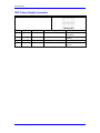
The extender board requires an external unregulated +/-12V to +/-15V supply for its analog
circuits. This supply must be brought in on TB2. The supply used can be the same as that used
for the analog circuits on the Mini-PMAC itself. If it is desired to maintain the provided optical
isolation between this analog circuitry and the digital 5V circuitry on the Mini-PMAC itself, this
must be a separate supply from the 5V supply for the Mini-PMAC, and the analog common
(AGND) must not be tied to the digital common (GND), except possibly at the signal system
“star” grounding point.
The digital 5V circuitry on the extender board is supplied automatically through the cable from
the Mini-PMAC board.
Note
The green “power-good” LED on the board (component D9) will be lit
only if all of the following signals are present:
•
•
•
•
The A+12V/+15V positive analog supply
The A-12V/-15V negative analog supply
The A+5V internal analog supply from the on-board regulator
The DAC clock signal from the Mini-PMAC
If any of these signals is not present, the D9 LED will go off, and the on-board relay supplying
power to the output op-amps will open, disabling the analog outputs.
Mini-PMAC Connection
The extender board is connected to the Mini-PMAC through the provided 16-strand flat cable.
This cable connects header JS1 on the extender board to header J7 on the Mini-PMAC.
The J7 header on the Mini-PMAC can also be used to connect the Mini-PMAC to the ACC-28A
or ACC-28B A/D-converter board. To connect the Mini-PMAC to both an ACC-28 board and an
extender board, daisy-chained them on a 3-drop cable. There is no signal or address conflict
between these two accessory boards.
Amplifier Connection
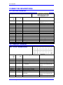
The analog command outputs, the amplifier-enable/direction outputs, the amplifier fault inputs,
and the AGND reference voltage of the extender board are connected to the amplifier(s) through
terminal block TB1.
The analog command outputs can be connected as single-ended outputs, in which the command
voltage is the voltage of DAC+ with respect to AGND. In this case, the DAC- pin should be left
floating – do not ground this output if you are not using it! Alternately, the analog outputs can be
used in differential mode, in which the command voltage is the voltage of DAC+ with respect to
DAC-. In this case, it is still important to tie the AGND reference voltage of the extender board
to the analog reference voltage of the amplifier.
If Option 14M, which provides all of the flag inputs for Channels 3 and 4, is present on the MiniPMAC, the amplifier-fault inputs FAULT3 and FAULT4 can be brought in either on the extender
board, or the Mini-PMAC itself. If the rest of the amplifier signal connections for these channels
are brought in on the extender board, it is probably advisable to bring the fault signals in on the
extender board also. Whichever input is not used should be left floating to avoid signal conflict.
Connecting the Board
3