1
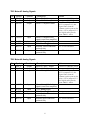
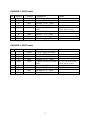
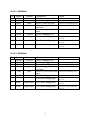
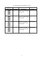
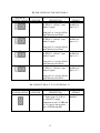
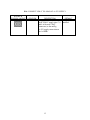
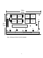
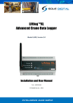
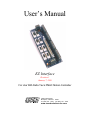
User’s Manual
EZ Interface
Revision 1
January 7, 1999
For Use With Delta Tau’s PMAC Motion Controller
7269 Imbach Place
Moorpark, California
tel (805) 531 - 0303
93021
fax (805) 531 - 0303
www.sound-solutions-inc.com
Introduction
The EZ Interface board is an interface board designed to interface Delta Tau’s PMAC?
(Programmable Multi-Axis Controller) with the typical external connections of your servo system
(i.e. your amplifiers, encoders, limit switches, etc.). As its name implies, this board provides an
easy plug-n-play interface from PMAC to external components through the following features:
-
Compatible with PMAC-PC, PMAC-Lite, PMAC-VME, and Mini-PMAC
Socketed & removable terminal blocks
Pin descriptions provided right on the board
Status LEDs for +5V, +12V, and -12V
UL rated relays for amplifier enable signals
DB9 connectors for encoders and flags (home, amp fault, and limits)
Dedicated pins for cable shielding with optional connection to ground
Multiple connection points for grounds and voltage supplies
DIN rail mountable (with housing)
Six mounting holes for standalone use
Over-voltage protection when using external 5V supply
Lever assisted connector to PMAC’s “JMACH” cable
Digital and analog ground planes to reduce electrical noise
About Revision 1
If you are using an EZ Interface that was purchased prior to December 1997, please read this
section. As of December 1997, the EZ Interface has been incorporated with new and improved
features to provide better reliability. A summary of the new changes are as follows:
Changes:
1. The four encoder connectors (9 pin DB9 connectors, for encoders 1 through 4) are now
female connectors. They also have new pin assignments.
Pin Number
Previous EZ
Interface
EZ Interface Rev 1
1
2
3
4
5
6
7
8
9
C+
B+
A+
+5V
GND
CBAShield
+5V
C+
B+
A+
Shield
CBAGND
1
2. The four "Flag" connectors (9 pin male DB9 connectors, for encoders 1 through 4) are now
male connectors.
3. The length of the EZ Interface has been increased to 7.785 inches (197.74 mm).
Additions:
1. The EZ Interface is now a four layer board with digital and analog ground planes on the top
and bottom layers. This helps shield the signals on the board from receiving and emitting
electrical noise. Decoupling capacitors are provided between the circuit board's and the DB9
connectors' mounting holes and the ground planes.
2. The four encoder connectors now have decoupling capacitors connected across each
differential encoder signal pair. This helps reject electrical noise received by the encoder
cables that may contaminate the encoder signals.
3. The power signals on the "Flag" connectors (9 pin male DB9 connectors, for flag signals 1
through 4) , now called LIM+V, can now be jumpered to provide +15 volts (as in the
previous revision of the EZ Interface), or can be jumpered to provide a separate voltage
through pin 4 of TB2 (this pin is labeled LIM+V). The latter case allows the use of
electronically powered travel limit switches requiring a supply voltage other than the analog
+15 volts normally used.
Connector Description
The EZ Interface board contains several connectors. The function of each of these connectors are
described below.
J1 : 60 Pin Header Connector to PMAC’s “JMACH”
This connector serves as the main connection between Delta Tau’s PMAC? and the EZ Interface
board. On PMAC’s “JMACH” connector (PMAC’s J7 and J8 for the PMAC-PC version PMACLite version, and/or PMAC’s P2 and P3 for the PMAC-VME version), a 60-pin ribbon cable is
connected. The other end of this ribbon cable connects to J1 on the EZ Interface board. All the
encoder, analog, and various flag signals are carried on this cable. Also, the +5, +12 and -12 volt
power supply signals are also included.
TB1 : 4 Pin Removable Terminal Block (+5V, GND, FEFCO)
This removable terminal block provides the digital +5 volt power supply, two connections to
digital ground (GND), and the FEFCO (fatal following error/watch dog) signal from PMAC. The
nearby green LED lights when a proper 5 volt level is detected. This terminal block can be used
to bring in a 5 volt supply to power PMAC and the encoders (for standalone applications), or it
can be used to connect to PMAC’s already-provided 5 volt supply (in this case, PMAC usually is
provided 5 volts from the bus). Jumper E9 provides connection from this terminal block to pins 1
and 2 on connector J1. Allowing you to have a separate 5 volt supply for the encoders, if
necessary.
2
TB2 : 4 Pin Removable Terminal Block (+12V, -12V, AGND)
This removable terminal block provides the analog +12 and -12 volt power supply, a separate
power supply for the travel limit switches (LIM+V) and a connection to analog ground (AGND).
The nearby green LEDs light when a proper +12 and -12 volt level is detected for each voltage.
This terminal block can be used to bring in a +12 and -12 volt supply to power PMAC (for
standalone applications).
TB3 - TB6 : 8 Pin Removable Terminal Block (DAC, AENA, FAULT)
These removable terminal blocks provide the following motor channel signals: DAC+, DAC-,
amplifier enable (AENA), amplifier fault (FAULT), analog +12 volt power supply, analog ground
(AGND), and two connections to the amplifier enable relays. Each of the four terminal blocks are
for each of the four motor channels, with the DAC+, DAC-, AENA, and FAULT signals unique
to each motor channel. All signals originate from PMAC.
3
TB1
Pin
1
2
3
4
Symbol
+5V
GND
GND
FEFCO
Function
Common
Common
Common
Output
Description
+5VDC supply
PMAC’s digital ground
Symbol
A+12V
A-12V
AGND
LIM+V
Function
Input
Input
Common
Input
Description
+12V analog supply
-12V analog supply
PMAC’s analog ground
Travel limits' analog supply
Notes
see E9
Fatal Following Error /
Watchdog Timer
TB2
Pin
1
2
3
4
4
Notes
See E14-- can be shorted to
A+12V
TB3 Motor #1 Analog Signals
Pin
1
2
3
Symbol
DAC1+
DAC1AENA1
Function
Output
Output
Output
4
FAULT1
Input
5
6
7
A+12V
AGND
RLY1A
Input
Common
Input
8
RLY1B
Input
Description
Motor 1’sDAC+ output
Motor 1’s DAC- output
Motor 1’s amplifier enable
Motor 1’s amplifier fault
signal (comes from amplifier)
+12V analog supply
PMAC’s analog ground
normally closed connection
point on relay
normally open connection
point on relay
Notes
connects to JMACHx, pin 43
connects to JMACHx, pin 45
see E5 and TB3 pins 7 and 8;
if E5 is jumpered 1-2, this
signal comes from the
common contact point on the
relay; if E5 is jumpered 2-3.
this signal comes directly
from PMAC’s AENA
see E5 and schematics
see E5 and schematics
TB4 Motor #2 Analog Signals
Pin
1
2
3
Symbol
DAC2+
DAC2AENA2
Function
Output
Output
Output
4
FAULT2
Input
5
6
7
A+12V
AGND
RLY2A
Input
Common
Input
8
RLY2B
Input
Description
Motor 2’s DAC+ output
Motor 2’s DAC- output
Motor 2’s amplifier enable
Motor 2’s amplifier fault
signal (comes from amplifier)
+12V analog supply
PMAC’s analog ground
normally closed connection
point on relay
normally open connection
point on relay
5
Notes
connects to JMACHx, pin 44
connects to JMACHx, pin 46
see E5 and TB4 pins 7 and 8;
if E5 is jumpered 1-2, this
signal comes from the
common contact point on the
relay; if E5 is jumpered 2-3.
this signal comes directly
from PMAC’s AENA
see E6 and schematics
see E6 and schematics
TB5 Motor #3 Analog Signals
Pin
1
2
3
Symbol
DAC3+
DAC3AENA3
Function
Output
Output
Output
4
FAULT3
Input
5
6
7
A+12V
AGND
RLY1A
Input
Common
Input
8
RLY1B
Input
Description
Motor 3’s DAC+ output
Motor 3’s DAC- output
Motor 3’s amplifier enable
Motor 3’s amplifier fault
signal (comes from amplifier)
+12V analog supply
PMAC’s analog ground
normally closed connection
point on relay
normally open connection
point on relay
Notes
connects to JMACHx, pin 29
connects to JMACHx, pin 31
see E5 and TB5 pins 7 and 8;
if E5 is jumpered 1-2, this
signal comes from the
common contact point on the
relay; if E5 is jumpered 2-3.
this signal comes directly
from PMAC’s AENA
see E7 and schematics
see E7 and schematics
TB6 Motor #4 Analog Signals
Pin
1
2
3
Symbol
DAC4+
DAC4AENA4
Function
Output
Output
Output
4
FAULT4
Input
5
6
7
A+12V
AGND
RLY1A
Input
Common
Input
8
RLY1B
Input
Description
Motor 4’s DAC+ output
Motor 4’s DAC- output
Motor 4’s amplifier enable
Motor 4’s amplifier fault
signal (comes from amplifier)
+12V analog supply
PMAC’s analog ground
normally closed connection
point on relay
normally open connection
point on relay
6
Notes
connects to JMACHx, pin 30
connects to JMACHx, pin 32
see E5 and TB6 pins 7 and 8;
if E5 is jumpered 1-2, this
signal comes from the
common contact point on the
relay; if E5 is jumpered 2-3.
this signal comes directly
from PMAC’s AENA
see E8 and schematics
see E8 and schematics
ENCODER 1 (DB9 Female)
Pin
1
2
3
4
5
Symbol
+5
C+
B+
A+
SHLD
Function
Output
Input
Input
Input
Shield
6
7
8
9
CBAGND
Input
Input
Input
Common
Description
+5VDC supply for encoder
Encoder 1’s “C+” signal
Encoder 1’s “B+” signal
Encoder 1’s “A+” signal
Connect to shield on encoder
cable
Encoder 1’s “C-” signal
Encoder 1’s “B-” signal
Encoder 1’s “A-” signal
PMAC’s digital ground
Notes
Description
+5VDC supply for encoder
Encoder 2’s “C+” signal
Encoder 2’s “B+” signal
Encoder 2’s “A+” signal
Connect to shield on encoder
cable
Encoder 2’s “C-” signal
Encoder 2’s “B-” signal
Encoder 2’s “A-” signal
PMAC’s digital ground
Notes
see E1-- can be shorted to
PMAC digital ground
ENCODER 2 (DB9 Female)
Pin
1
2
3
4
5
Symbol
+5
C+
B+
A+
SHLD
Function
Output
Input
Input
Input
Shield
6
7
8
9
CBAGND
Input
Input
Input
Common
7
see E2-- can be shorted to
PMAC digital ground
ENCODER 3 (DB9 Female)
Pin
1
2
3
4
5
Symbol
+5
C+
B+
A+
SHLD
Function
Output
Input
Input
Input
Shield
6
7
8
9
CBAGND
Input
Input
Input
Common
Description
+5VDC supply for encoder
Encoder 3’s “C+” signal
Encoder 3’s “B+” signal
Encoder 3’s “A+” signal
Connect to shield on encoder
cable
Encoder 3’s “C-” signal
Encoder 3’s “B-” signal
Encoder 3’s “A-” signal
PMAC’s digital ground
Notes
Description
+5VDC supply for encoder
Encoder 4’s “C+” signal
Encoder 4’s “B+” signal
Encoder 4’s “A+” signal
Connect to shield on encoder
cable
Encoder 4’s “C-” signal
Encoder 4’s “B-” signal
Encoder 4’s “A-” signal
PMAC’s digital ground
Notes
see E3-- can be shorted to
PMAC digital ground
ENCODER 4 (DB9 Female)
Pin
1
2
3
4
5
Symbol
+5
C+
B+
A+
SHLD
Function
Output
Input
Input
Input
Shield
6
7
8
9
CBAGND
Input
Input
Input
Common
8
see E4-- can be shorted to
PMAC digital ground
FLAG 1 (DB9 Male)
Pin
1
2
3
4
Symbol
AGND
AGND
HMFL
-LIM
Function
Common
Common
Input
Input
5
+LIM
Input
6
7
AGND
LIM+V
Common
Input/Output
Description
PMAC’s analog ground
PMAC’s analog ground
Motor 1’s home flag input
Motor 1’s negative travel
limit input
Motor 1’positive travel limit
input
PMAC’s analog ground
Travel limits' analog supply
8
LIM+V
Input/Output
Travel limits' analog supply
9
LIM+V
Input/Output
Travel limits' analog supply
Notes
Connects to JMACHx pin 55
Connects to JMACHx pin 53
Connects to JMACHx pin 51
See E14-- can be shorted to
A+12V
See E14-- can be shorted to
A+12V
See E14-- can be shorted to
A+12V
FLAG 2 (DB9 Male)
Pin
1
2
3
4
Symbol
AGND
AGND
HMFL
-LIM
Function
Common
Common
Input
Input
5
+LIM
Input
6
7
AGND
LIM+V
Common
Input/Output
Description
PMAC’s analog ground
PMAC’s analog ground
Motor 2’s home flag input
Motor 2’s negative travel
limit input
Motor 2’s positive travel limit
input
PMAC’s analog ground
Travel limits' analog supply
8
LIM+V
Input/Output
Travel limits' analog supply
9
LIM+V
Input/Output
Travel limits' analog supply
9
Notes
Connects to JMACHx pin 56
Connects to JMACHx pin 54
Connects to JMACHx pin 52
See E14-- can be shorted to
A+12V
See E14-- can be shorted to
A+12V
See E14-- can be shorted to
A+12V
FLAG 3 (DB9 Male)
Pin
1
2
3
4
Symbol
AGND
AGND
HMFL
-LIM
Function
Common
Common
Input
Input
5
+LIM
Input
6
7
AGND
LIM+V
Common
Input/Output
Description
PMAC’s analog ground
PMAC’s analog ground
Motor 3’s home flag input
Motor 3’s negative travel
limit input
Motor 3’s positive travel limit
input
PMAC’s analog ground
Travel limits' analog supply
8
LIM+V
Input/Output
Travel limits' analog supply
9
LIM+V
Input/Output
Travel limits' analog supply
Notes
Connects to JMACHx pin 41
Connects to JMACHx pin 39
Connects to JMACHx pin 37
See E14-- can be shorted to
A+12V
See E14-- can be shorted to
A+12V
See E14-- can be shorted to
A+12V
FLAG 4 (DB9 Male)
Pin
1
2
3
4
Symbol
AGND
AGND
HMFL
-LIM
Function
Common
Common
Input
Input
5
+LIM
Input
6
7
AGND
LIM+V
Common
Input/Output
Description
PMAC’s analog ground
PMAC’s analog ground
Motor 4’s home flag input
Motor 4’s negative travel
limit input
Motor 4’s positive travel limit
input
PMAC’s analog ground
Travel limits' analog supply
8
LIM+V
Input/Output
Travel limits' analog supply
9
LIM+V
Input/Output
Travel limits' analog supply
10
Notes
Connects to JMACHx pin 42
Connects to JMACHx pin 40
Connects to JMACHx pin 38
See E14-- can be shorted to
A+12V
See E14-- can be shorted to
A+12V
See E14-- can be shorted to
A+12V
E1 - E4: SHORT ENCODER SHIELD TO GND
E POINT &
PHYSICAL LAYOUT
LOCATION
DESCRIPTION
DEFAULT
E1
Jump pin 1 to 2 to short
Encoder 1’s shield to digital
ground (GND).
Jumper installed.
E2
Jump pin 1 to 2 to short
Encoder 2’s shield to digital
ground (GND).
Jumper installed.
E3
Jump pin 1 to 2 to short
Encoder 3’s shield to digital
ground (GND).
Jumper installed.
E4
Jump pin 1 to 2 to short
Encoder 4’s shield to digital
ground (GND).
Jumper installed.
11
E5 - E8: USE RELAY FOR AMP ENABLE
E POINT &
PHYSICAL LAYOUT
LOCATION
DESCRIPTION
DEFAULT
Jump pin 1 to 2 to use the relay
for PMAC’s “AENA1” (amp
enable 1) signal.
Jumper
installed on
pins 1 to 2.
E6
Jump pin 2 to 3 use the AENA1
signal directly from PMAC.
Jump pin 1 to 2 to use the relay
for PMAC’s “AENA2” (amp
enable 2) signal.
Jumper
installed on
pins 1 to 2.
E7
Jump pin 2 to 3 use the AENA2
signal directly from PMAC.
Jump pin 1 to 2 to use the relay
for PMAC’s “AENA3” (amp
enable 3) signal.
Jumper
installed on
pins 1 to 2.
E8
Jump pin 2 to 3 use the AENA3
signal directly from PMAC.
Jump pin 1 to 2 to use the relay
for PMAC’s “AENA4” (amp
enable 4) signal.
Jumper
installed on
pins 1 to 2.
E5
Jump pin 2 to 3 use the AENA4
signal directly from PMAC.
E9: CONNECT PMAC’S 5V TO EXTERNAL 5V
E POINT &
PHYSICAL LAYOUT
E9
LOCATION
DESCRIPTION
Jump pin 1 to 2 to tie PMAC’s
5V supply (pins 1,2 of J1) to
the external 5V supply
connection on pin 1 of TB1 and
the 5V going to the encoders
(pin 4 of P1 through P4).
12
DEFAULT
Jumper
installed.
E14: CONNECT LIM+V TO ANALOG A+12V SUPPLY
E POINT &
PHYSICAL LAYOUT
E14
LOCATION
DESCRIPTION
Jump pin 1 to 2 to tie the travel
limits' LIM+V supply (pins 7, 8
and 9 of the male "Flag"
connectors) to the analog
A+12V supply connection on
pin 1 of TB2.
13
DEFAULT
Jumper
installed.
7.785 in
198 mm
Encoder 3
Encoder 1
E3
TB1
Encoder 4
E9
Encoder 2
E4
2.81 in
71 mm
TB6
Flag 2
Flag 4
Flag 1
E1
E2
E6
TB4
TB5
Note: All holes are 0.150 inch (3.8 mm) diameter.
15
TB2
E14
E7
E8
Flag 3
E5
TB3