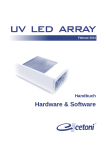
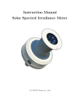
1
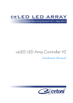
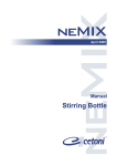
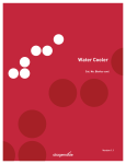
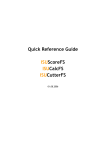
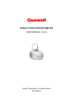
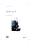
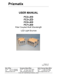
ceLED LED ARRAY Original Operating Manual 1.00 – May 2015 ceLED 96 V2 Hardware Manual The information and data contained in this document are subject to change without prior notice. No part of this document may be copied or transmitted without the express consent of cetoni GmbH, irrespective of the means used for this purpose – electronic or mechanical. The general terms of cetoni GmbH apply. Agreements deviating from these terms must be made in writing. Copyright © cetoni GmbH – Automation and Micro Systems. All rights reserved. 2 LED Array Manual cetoni GmbH Wiesenring 6 07554 Korbussen Germany Tel.: +49 (0) 36602 338-0 Fax: +49 (0) 36602 338-11 E-Mail: [email protected] Internet: www.cetoni.de LED Array Manual 3 1. Overviews and Directories 1.1. Contents 1. Overviews and Directories ............................................................. 4 1.1. Contents .................................................................................................. 4 1.2. Revision History ....................................................................................... 6 2. Introduction ................................................................................... 7 2.1. Preface..................................................................................................... 7 2.2. Symbols and Keywords............................................................................ 7 3. Basic Information ........................................................................... 9 3.1. Radiation Protection Advice .................................................................... 9 3.2. Standards and Guidelines...................................................................... 10 3.3. Intended Use ......................................................................................... 11 3.3.1. General Description of the Device ........................................................ 11 3.3.2. Safety Measures .................................................................................... 11 3.3.3. Safe Operation Measures ..................................................................... 13 3.3.4. Device Condition ................................................................................... 13 3.4. Warranty and Liability ........................................................................... 14 3.5. Scope of Supply ..................................................................................... 15 4. Hardware Operation .................................................................... 16 4.1. Hardware Overview .............................................................................. 16 4.2. Status LEDs ............................................................................................ 17 4.3. Connecting to Control Unit ................................................................... 18 4.4. Connecting the Cooling Unit ................................................................. 19 4.4.1. Introduction .......................................................................................... 19 4.4.2. Cooling Medium .................................................................................... 21 4.4.3. Tube Installation.................................................................................... 21 4.4.4. Tube Removal........................................................................................ 22 4 LED Array Manual 4.5. Micro Titer Plate Installation ................................................................. 23 5. Transport, Maintenance, Disposal ................................................ 25 5.1. Transport and Storage ........................................................................... 25 5.2. Maintenance and Care .......................................................................... 25 5.3. Disposal ................................................................................................. 25 LED Array Manual 5 1.2. Revision History Rev Date Change 1.00 13.05.2015 Manual Creation 6 LED Array Manual 2. Introduction 2.1. Preface Thank you for choosing a cetoni product. With this manual we would like to support you in using the device. For additional questions or comments please feel free to contact us directly. Please read this manual carefully before operating the device. 2.2. Symbols and Keywords This manual uses the following symbols, intended to help you navigate the document: TIP User tips and useful information to simplify the use of the software. IMPORTANT Important information and additional, particularly useful information. This symbol does not refer to dangerous or hazardous situations. CAUTION A potentially hazardous situation. Failing to avoid it may cause damage to the product or its environment. LED Array Manual 7 WARNING A potentially dangerous situation. Failing to avoid it may cause light or insignificant injury or material damage. 8 LED Array Manual 3. Basic Information 3.1. Radiation Protection Advice WARNING Emitted light can cause damage to skin and eyes (including the risk of blindness). Therefore, when integrating this device into your application you should take special care not to expose persons, animals or items to the emitted light inadvertently. Persons operating the LED array must wear suitable gear to protect against dangers caused by artificial optical radiation. It must also be ensured that persons without UV-protection cannot enter the UV-radiation area. If required, the UV-radiation area must be enclosed by a radiation-proof barrier. Depending on the type of radiation, additional safety measures stipulated by the LED manufacturer may apply. Please be aware that the emitted radiation may cause various types of damage to skin and eyes. LED Array Manual 9 The following table shows possible types of radiation damage. Wavelength Skin Damage Eye Damage 280nm…400nm Accelerated skin aging, Corneal inflammation (UVA and UVB radiation is not stronger pigmentation, and conjunctivitis, lens burns, risk of cancer opacity Reddening, burns Photochemical and visible) 400nm…800nm (visible spectrum) thermal damage to retina and receptors 800nm…1550nm Reddening, burns (IR-radiation is not visible) Lens opacity, retinal burns WARNING Always avoid direct radiation into the eyes. Even low radiation intensity can cause glare or even injury. WARNING Never look directly at (presumably) inactive LEDs. The LEDs in question may emit radiation outside of the visible spectrum, which can also cause damage or injury. 3.2. Standards and Guidelines cetoni GmbH hereby declares under its sole responsibility that the product complies with the health and safety requirements of the relevant European guidelines. 10 LED Array Manual 3.3. Intended Use 3.3.1. General Description of the Device The LED array is used for the irradiation of separate areas with LEDs of similar or different wavelengths. Radiation intensity can be adjusted separately for each area / channel. The maximum intensity and wavelength of the emitted radiation is governed by the number and type of LEDs being used. At the time of creating this document, LEDs ranging from 255 nm to 1550 nm in wavelength are commercially available. IMPORTANT The device must not be used as a medical product or for medical purposes. The device must not be used on people or for therapeutic purposes. WARNING The device must not be used in potentially explosive environments. There is a risk of fire when exposing flammable substances/substrates. 3.3.2. Safety Measures Operator safety and failure-free operation of the device can only be guaranteed when using original equipment parts. Warranty claims are void if damage was causes by using third-party equipment or third-party material. The device was developed and designed in such way as to largely rule out dangers, if used properly. Nevertheless, you should observe the following safety measures to rule out any residual danger. LED Array Manual 11 The device is not intended or designed for operation in potentially explosive environments. Therefore, using the device in such environments is forbidden! When operating the device the laws and regulations applicable at the place of operation must be observed. In the interest of a safe work process operators and users are responsible for observing such regulations. When radiating substrates with light (of various wavelengths) energy enters into the substrate. There is also a possibility of creating chemical (exothermic) reactions in the substrate. The substrate may ignite. The operator must make sure that there is no ignition. The operator must ensure that any ignition is extinguished immediately. Flammable substances may be exposed to radiation only under continuous supervision! Before each operation of the device the user has to ensure that the device is functioning safely as is in proper condition. The user must be familiar with the operation of the device. Before starting operation the device and wiring must be checked for damage. Damaged wires and plugs must be replaced immediately. If a support or tripod is used, it must be sufficiently stable and able to support the required weight. 12 Cables must be routed in such way as to rule out any trip hazards. LED Array Manual If liquid enters the device, the main power plug must be removed from the mains socket immediately. The device must then be sent to cetoni GmbH for inspection and repair. 3.3.3. Safe Operation Measures 3.3.3.1 Electromagnetic Emissions The device is designed for usage in any facility, including living areas and facilities directly connected to a public supply network that also supplies buildings used for residential purposes. 3.3.3.2 ESD Discharge Floors should be wood or concrete or covered with ceramic tiles. If floors are covered with synthetic material, relative air humidity must be at least 30%. 3.3.3.3 Electrical Disturbances Supply voltage quality should be equal to a typical business or hospital environment. 3.3.3.4 Magnetic Disturbances Power lines, including those of other devices, should not be placed near the device or its cables. Portable and mobile two-way radios should be kept at the minimum safe distance from the device and its wiring. 3.3.4. Device Condition Despite flawless workmanship, the device may be damaged during operation. Therefore, you should visually inspect the device before each use. Pay particular attention to crushed cables and deformed plugs. If you find any damage, please refrain from using the device and contact cetoni GmbH immediately. We will repair your device as soon as possible. Never attempt to repair the device yourself. LED Array Manual 13 3.4. Warranty and Liability The device has left our facilities in perfect condition and may only be opened by cetoni GmbH. If the device is opened by an unauthorized person, all warranty and liability claims shall be void, in particular those referring to personal injury. The warranty period is one year from the day of delivery. Any work done on the device within this period shall not extend or renew the warranty. Cetoni GmbH assumes responsibility for its devices with respect to safety, reliability and function only if installation, readjustment, changes, extensions and repairs are done by cetoni GmbH or an authorized party, and if the device is used in accordance with the user manual. The device complies with the applicable safety rules and standards. Cetoni GmbH reserves all property rights for the relevant wiring, processes, names, software and devices. 14 LED Array Manual 3.5. Scope of Supply The following items should be included in the delivery. Cable set for the connection of LED array modules LED array Protective cover LED Array Manual 15 4. Hardware Operation IMPORTANT Please carefully and completely read this manual and the associated software manual as well as the manual for the LED array controller V2 before operating your LED array. 4.1. Hardware Overview The following image contains an overview of the LED array hardware. Slots for safety circuit Power LEDs Status LEDs Controller interface Cooling unit connectors Image 1 – Hardware Overview To protect against optical radiation the LED array may only be operated with the supplied cover in place. 16 LED Array Manual Plates for cover sensor Image 2 – Safety cover The plates incorporated into the cover activate the safety sensor on the LED array, so the LEDs can be illuminated. When the cover is removed from the array the LEDs are turned off. IMPORTANT The LED array is deactivated automatically when the cover is not mounted to the device. WARNING The LED array cover can heat up to more than 100°C. Do not touch the cover during operation and let it cool down after turning off the device. There is a risk of burning due to hot components. 4.2. Status LEDs The following status LEDs are available: LED Array Manual 17 Image 3 – Status LEDs LED Meaning Power Logic Power for logic circuits available Power LED Bank 1 Power for power driver 1 available Power LED Bank 2 Power for power driver 2 available Communication Signals data traffic through the control cable to the controller High Temperature Illuminated when the temperature of the LED array board exceeds the warning threshold Over Temperature Illuminated when the temperature of the LED array board exceeds the maximum value. The LED array will be deactivated. Cover Open Illuminated when the cover is not mounted on the LED array. The LED array will be deactivated. No micro plate Reserved – this LED is currently not in use 4.3. Connecting to Control Unit Connect the LED array to the control unit using the supplied cable. LED Array Image 4 – Control Unit - ceLED LED Array Controller V2 18 LED Array Manual 4.4. Connecting the Cooling Unit 4.4.1. Introduction The LED array can be connected to an external cooling unit (e.g. Huber minichiller). This will cool the LED array board during operation to prevent overheating and triggering of the array’s safety deactivation system. CAUTION Adjust the cooling temperature to a maximum of 5 – 7 Kelvin below room temperature to avoid condensation on the LED board and the resulting short circuits. To hook up an external cooling unit the array is fitted with two connectors using a Festo QS-G1/4-12 push-in fitting (article number 186350). Release ring Image 5 – Cooling Unit Connection - Festo QS-G1/4-12 push-in fitting CAUTION Observe the contents of the datasheet for the Festo QS-G1/4-12 push-in fitting (article number 186350) on the manufacturer’s internet site to avoid exceeding the maximum values (pressure, torque, etc.) and prevent material damage due to unsuitable coolants. LED Array Manual 19 Alternatively, you may also use tube connectors with an inside diameter of 8 mm to connect the tubes. All wetted parts of these tube connectors are made from stainless steel (see image below). Image 6 – Tube Connector 1/4x8 A2 20 LED Array Manual 4.4.2. Cooling Medium When choosing the cooling medium please consider its compatibility with the materials and wetted parts of the LED array. Component Material LED array base Anodized aluminum LED Array bottom seal EPDM Festo push-in fitting housing Nickel-plated brass tube seal NBR Tube clamp segment Stainless steel CAUTION Choose the cooling medium in such way as to prevent damage to wetted parts and seals. 4.4.3. Tube Installation CAUTION When connecting the LED array to a cooling circuit the array must be turned off and disconnected from power to avoid damage and short circuits due to humidity. Use a tube with an outside diameter of 12 mm. The tube must be cut straight and any burrs removed in order to fit properly and avoid damage to the inside seal. 1 Insert the tube into the connector as far as it will go. Make sure the tube is inserted into the inside seal. Depending on the tube’s and the seal’s tolerances, the tube making contact with the seal may be misinterpreted as a stop position. 2 Check if there is a proper connection by lightly tugging on the tube. LED Array Manual 21 CAUTION Before activating the LED array please check the tightness of the cooling circuit. The LED array may be activated only in the absence of coolant leaks. 4.4.4. Tube Removal CAUTION Tubes may be removed only when the array is turned off and disconnected from power to avoid damage and short circuits due to humidity. A tube can be removed simply by pressing down the release ring and keeping it pressed. Carefully pull the tube out of the fitting. Micro Titer Plate Installation 22 LED Array Manual 4.5. Micro Titer Plate Installation Insert the micro titer plate in such way that it clicks into place between the fixing pins. Image 7 – Inserting a Micro Titer Plate CAUTION If possible, only use transparent micro titer plates, since dark and opaque plates tend to heat up or even melt due to the absorbed radiation energy. The LED array was developed to create high-intensity optical radiation. Optimized heat management (water cooling) ensures that the efficiency-related waste heat is dissipated in the optimal way. As a result the LED board and its LED Array Manual 23 components will remain insignificantly above the temperature of the cooling medium. However, due to physical factors the energy of the emitted light is turned to heat when it impinges on an item, such as the cover or the substrate (titer plate). Therefore, high performance operation of the LEDs used in the array and extended exposure periods may lead to very high temperatures (> 100°C) in the substrate or the cover. CAUTION Avoid extended exposure periods at high intensity, since this will strongly heat up the cover and the radiation space, which in turn may lead to melting of the micro titer plate. TIP Mount an additional cooling device on the cover (e.g. heat sink with fan), in order to lower the temperature inside the irradiation chamber and enable extended exposure periods at high intensity. 24 LED Array Manual 5. Transport, Maintenance, Disposal 5.1. Transport and Storage If possible, use the original package for transporting and shipping the device. Otherwise, use a stable box and a sufficient amount of padding material. 5.2. Maintenance and Care When used properly the device is maintenance-free. Should you experience problems that you can’t fix yourself or that require opening the device, please contact cetoni GmbH to discuss further actions. The device may only be opened by cetoni GmbH or authorized service personnel. Violation of this rule will void the warranty and liability. The software manual provides additional information about problems in connection with operating software. Wipe the device with a moist (not wet) cloth. Make sure that no liquid can enter the inside of the device. For stronger soiling you may use a small amount of detergent or alcohol. 5.3. Disposal Please return your old devices to cetoni GmbH. We will take care of proper disposal according to the relevant electrical and electronic device regulations. LED Array Manual 25